
Chapter 21
Subsea Connections and Jumpers
Contents
21.1. Introduction
21.1.1. Tie-In Systems
21.1.1.1. Vertical Tie-In Systems
21.1.1.2. Horizontal Tie-In Systems
21.1.1.3. Comparison between Horizontal and Vertical Tie-In Systems
21.1.2. Jumper Configurations
21.2. Jumper Components and Functions
21.2.1. Flexible Jumper Components
21.2.1.1. End Fittings of Flexible Pipe
21.2.1.2. Corrosion Resistance
21.2.1.3. Advantages of Flexible Jumpers
21.2.2. Rigid Jumper Components
21.2.3. Connector Assembly
21.2.3.1. Connector Receiver
21.2.3.2. Connector
21.2.3.3. Connector Actuator
21.2.3.4. Soft Landing System
21.2.3.5. Connector Override Tool
21.2.4. Jumper Pipe Spool
21.2.5. Hub End Closure
21.2.6. Fabrication/Testing Stands
21.2.6.1. Transportation/Shipping Stands
21.2.6.2. Testing Equipment
21.2.6.3. Running Tool
21.2.6.4. Jumper Measurement Tool
21.2.6.5. Metal Seal Replacement Tool
21.2.6.6. Hub Cleaning Tool
21.2.6.7. Vortex-Induced Vibration Suppression Devices
21.2.6.8. ROV-Deployable Thickness Gauge
21.3. Subsea Connections
21.3.1. Bolted Flange
21.3.2. Clamp Hub
21.3.3. Collet Connector
21.3.4. Dog and Window Connector
21.3.5. Connector Design
21.3.5.1. Connector Stresses
21.3.5.2. Makeup Requirements
21.3.5.3. Testing
21.4. Design and Analysis of Rigid Jumpers
21.4.1. Design Loads
21.4.2. Analysis Requirements
21.4.2.1. Tolerance Analysis
21.4.2.2. ROV Access Analysis
21.4.2.3. Loading Analysis
21.4.2.4. Thermal Analysis
21.4.3. Materials and Corrosion Protection
21.4.4. Subsea Equipment Installation Tolerances
21.5. Design and Analysis of a Flexible Jumper
21.5.1. Flexible Jumper In-Place Analysis
21.5.1.1. Allowable Jumper Loads for Jumper In-Place Analysis
21.5.1.2. Analysis Methodology
21.5.2. Flexible Jumper Installation
21.5.2.1. Design Criteria
21.5.2.2. Installation Steps
21.1 Introduction
In subsea oil/gas production system, a subsea jumper is a short pipe connector used to transport production fluid between two subsea components, for example, tree and manifold, manifold and manifold, or manifold and export sled. It may also connect other subsea structures such as PLEM/PLETs and riser bases. In addition to production fluid, it can also be a pipe by which water/chemicals are injected into a well.
21.1.1 Tie-In Systems
Subsea fields have been developed using a variety of tie-in systems in the past decades. Different types of horizontal and vertical tie-in systems and associated connection tools are used for the tie-in of flowlines, umbilicals, and other applications. For flowlines, the subsea tie-in systems are used to connect tree to manifold, tree to tree, and pipeline end to tree or manifold. For subsea control systems, the subsea tie-in systems are used to connect umbilicals to tree or manifold.
The horizontal tie-in connection systems are mainly used in shallow water with diver-based installation, such as expansion spools used for connecting pipeline with a fixed riser nearby the platform. In recent years, subsea engineering has undergone a fundamental change in that it has gone from being a diver-dominated activity to the use of remote systems for the construction of deepwater field developments. Horizontal connecting rigid spools are used in deep water with the aid of ROVs. Most of the horizontal connection systems are based on mechanically bolted flange joints, whereas the vertical spool connection system uses guideline-deployed inverted U- or M-shaped rigid spools with collet connectors.
21.1.1.1 Vertical Tie-In Systems
Vertical jumpers, mainly adopted in the Gulf of Mexico, are typical vertical tie-in systems, which are generally characterized by an inverted U-shaped rigid spool, and use mechanical collet connectors at each end as shown in Figure 21-1a. The vertically connected jumper system consists of a pipe spool between two vertically oriented downward connectors (hydraulic or mechanical type) with metal-to-metal seals for piping connections between subsea facilities (tree to manifold, manifold to PLET, etc.). The actuated half of the connector is part of the retrievable jumper assembly with the mating hub attached to the subsea equipment. The jumper connectors are landed onto upward hubs, made up, and tested to verify seal integrity.
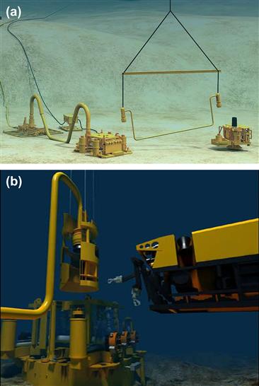
Figure 21-1 Vertical Tie-In Systems [1]
Vertical connections are installed directly onto the receiving hub during tie-in. Because the vertical connection system does not require a pull-in capability, it simplifies the tool functions, provides a time efficient tie-in operation, and reduces the length of rigid spools. Stroking and connection are carried out by the connector itself, or by the ROV-operated connector actuation tool (CAT) system as shown in Figure 21-1b.
21.1.1.2 Horizontal Tie-In Systems
Figure 21-2 shows a horizontal tie-in system, which can be used for both first-end and second-end tie-in of flowlines. The termination head is hauled into the tie-in point by use of a subsea winch. Horizontal tie-in may be made up by clamp connectors operated from a tie-in tool, by integrated hydraulic connectors operated through a ROV, or by nonhydraulic collet connectors with assistance from a CAT and ROV. Horizontal connection leaves the flowline/umbilical in a straight line, which is easily protected if overtrawling from fishermen occurs.
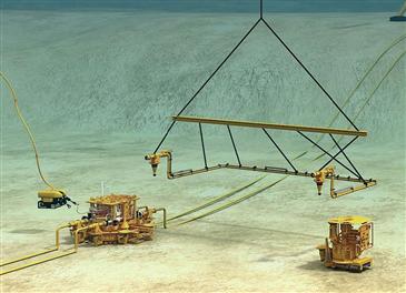
Figure 21-2 Horizontal Tie-in System [1]
The installation procedure for a horizontal tie-in system is illustrated in Figure 21-3 and described here:
• The spool of the horizontal tie-in system hooked up to a spreader beam is deployed and lowered to within a few meters above the target areas on the subsea structures as shown in Figure 21-2.
• The spool is lowered until the stab on the first termination head enters the stab receptacle on the tie-in porch as shown in Figure 21-3a. The second termination head will align horizontally as the spool continues to be lowered until the stab enters the stab receptacle and lands on the tie-in porch.
• The CAT is landed and locked on the first termination head by the ROV as shown in Figure 21-3b.
• The termination head is leveled and locked in the horizontal position. The protection caps are removed from the connector and the inboard hub as shown in Figure 21-3c.
• The termination head is stroked against the inboard hub and the connector is closed as shown in Figure 21-3d. A pressure test is carried out to verify the integrity of the connector seal. The CAT is unlocked and lifted from the termination head and inboard hub. The connection procedure is repeated to connect the second termination head to the inboard hub without returning the CAT to the surface vessel.
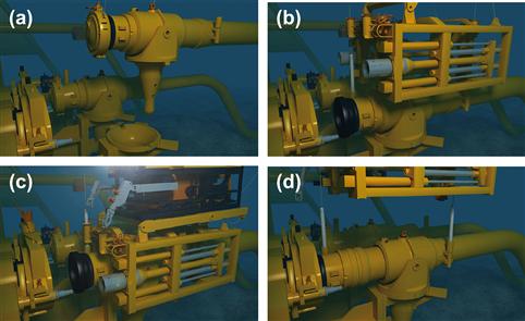
Figure 21-3 Installation Procedure for a Horizontal Tie-In System [1]
Figure 21-4 shows a well-to-manifold jumper that uses a horizontal tie-in system. This system was used in the water injection system of BP’s Greater Plutonio project.

Figure 21-4 Well Pu-PG to Manifold Jumper [2]
21.1.1.3 Comparison between Horizontal and Vertical Tie-In Systems
Table 21-1 summarizes a comparison between horizontal and vertical tie-in connection systems. The main technical disadvantages of the horizontal tie-in system over the vertical system include increased offshore operation time and increased complexity and reliance on ROVs. However, these disadvantages are largely offset by the advantages of reduced subsea structure size, simplicity of the flowline connector, and lower vessel/weather dependence [3].
Table 21-1. Comparison between Horizontal and Vertical Tie-In Systems
| Evaluation Issue | Horizontal Connection | Vertical Connection |
| Tie-in/connection required equipment | Relatively complex ROV to deploy and operate all equipment. | Relatively simple deployment equipment, and reliance on ROV to perform tasks is relatively low. |
| Duration of tie-in | Long. | Short. |
| Connector complexity and size | Simple; API/ANSI flange or clamp connector. Connector weight is comparatively low. | Complex; collet connector required either with integral stroking mechanism or separate running tool. Connector weight is on the order of several tons. |
| Metrology and fabrication accuracy | Medium level of accuracy required, since connection system can elastically deform spool for alignment if required. | High level of accuracy required since system has no means of correcting for inaccuracy other than by the connector. |
| Possibility of snagging by anchors and others | Relatively low, since the system stays close to seabed. | |
| Vessel requirements | ||
| Seal change | Relatively simple; push back and replace seal with ROV seal. | Depends on collet connector brand. Some are relatively involved: recover connector and flowline to surface/deck, change seal, and redeploy flowline. Some may be replaced with ROV tool after lifting spool clear. |
| Weather dependence | Very low, since operation is independent of vessel motion. | Relatively high due to dependence on guidelines. |
21.1.2 Jumper Configurations
A typical jumper consists of two end connectors and a pipe between the two connectors. If the pipe is a rigid pipe, the jumper is called a rigid jumper; otherwise, if the pipe is flexible, the jumper is called a flexible jumper.
Figure 21-5 shows some rigid jumper configurations. For the rigid pipe jumpers, the M-shaped style and inverted U-shaped style are two commonly used styles. There is also the horizontal Z-shaped style and so on. Jumper configurations are dictated by design parameters, interfaces with subsea equipment, and the different modes in which the jumper will operate. The configurations in Figure 21-5a and c use bends to connect straight pipes, while that in Figure 21-5b uses elbows to connect rigid pipes. The extended part of the elbows is designed for the erosion of sand. For the case shown here, the production flow should move from right to left.

Figure 21-5 Rigid Jumper Configurations
The subsea rigid jumpers between various components on the seabed are typically rigid steel pipes that are laid horizontally above the seabed. After the subsea hardware is installed, the distances between the components to be connected are measured or calculated. Then the connecting jumper is fabricated to the actual subsea metrology for the corresponding hub on each component, in which the pipes are fabricated to the desired length and provided with coupling hubs on the ends for the connection between the two components. Once the jumper has been fabricated, it is transported to the offshore location for the deployment of subsea equipment. The jumper will be lowered to the seabed, locked onto the respective mating hubs, tested, and then commissioned.
If the measurements are not precisely made or the components moved from their originally planned locations, new jumpers may need to be fabricated. The distance and the orientation between the subsea components must be known in advance before the flowline jumpers can be fabricated because the lengths will be critical. Also, a small change in the jumper configuration should be considered when the jumper is lowered below the water surface and the dead load of jumper changes due to the buoyancy: otherwise, the jumper’s dimensions may change and the jumper installation may fail. After the installation, if one of the components needs to be retrieved or moved, it is a time-consuming task to disconnect the flowline jumper from the component.
Figure 21-6 shows a configuration for a subsea flexible jumper. It consists of two end connectors and a flexible pipe between the two connectors. The subsea flexible jumpers are usually used for transporting fluid between two subsea components. They are also used to separate the rigid riser from the vessel to effectively isolate the riser from the fatigue due to the motions of the FPSO. For example, both rigid and flexible jumpers are used in a FSHR (Free Standing Hybrid Riser) system as shown in Figure 21-7. The FSHR consists of a vertical steel pipe (riser) tensioned by a near-surface buoyancy can with a flexible jumper connecting the top of the riser and the FPSO. An M-shaped rigid jumper is used to connect the vertical riser and a PLEM.

Figure 21-6 Flexible Jumper Configuration

Figure 21-7 Rigid and Flexible Jumpers Used in FSHR System [4]
21.2 Jumper Components and Functions
21.2.1 Flexible Jumper Components
A typical flexible jumper consists of two end connectors and a flexible pipe between the two connectors. Figure 21-8 shows the components of a Coflexip flexible jumper.

Figure 21-8 Flexible Jumper Components [5]
The Coflexip subsea flexible jumper consists of a number of functional layers, namely: (1) a stainless steel internal casing, which is designed to resist external pressure; (2) a thermoplastic sheath, which creates a fluid seal; (3) a helically wound steel wire, which is designed to resist internal pressure; (4) an axial armored wire, which is for tensile load reinforcement; (5) an external polymer sheath for protection from the environment; and (6) an optional external stainless steel carcass for additional protection.
21.2.1.1 End Fittings of Flexible Pipe
The standard end fittings installed on the subsea flexible jumper are produced with high specification carbon steel coated with ultra-high-corrosion-resistant and damage-tolerant Nikaflex® cladding. Standard terminations are available with API flanges, Grayloc®, Cameron hubs, or hammer unions.
21.2.1.2 Corrosion Resistance
The subsea jumpers for HP/HT flowlines should use the corrosion resistance of high-performance materials technology to provide a high-pressure, high-temperature, corrosion-resistant pipe. The pipes are designed and specified to resist the worst operational conditions. Especially all pipe structures are well adapted to resist corrosive agents such as water, H2S, CO2, aromatics, acids, and bases without loss of mechanical design life integrity.
21.2.1.3 Advantages of Flexible Jumpers
The advantages of flexible jumpers can be summarized as follows:
• H2S and corrosion resistant;
• High-temperature resistance;
• Suitable for dynamic or static service;
• Excellent fatigue design life;
• High resistance to collapse;
The disadvantages of flexible jumpers are expansive and smaller diameter for a higher internal pressure.
21.2.2 Rigid Jumper Components
The jumper connection system is configured with steel pipe and mechanical connections at each end for connection to the subsea facility’s piping. The metal seal is retained and sheltered within the connector during installation and retrieval. The connector design is capable of resisting the design loads due to the combined effects of internal pressure, external bending, torsion, tensile, thermal, and installation loads.
In the design of a rigid jumper system, the following items should be considered: (1) The jumper system is installable by a vessel; (2) the jumper components are independently retrievable from the connector receiver (or support structure); and (3) all parts of the system are analyzed with respect to reliability and expected failure rates. The system is designed to minimize failures.
For the design of components for a rigid jumper system, the following items should be considered:
• Materials for the components should be selected so as to minimize potential galling or damage to sealing surfaces during assembly, installation, and maintenance.
• A redundancy philosophy for all parts of the system should be analyzed with respect to safety, cost, and reliability.
• Jumper components of the same design should be interchangeable.
• Standardized parts should be used throughout the system.
• All system components should be compatible with the intended fluids (e.g., all produced, injected, and completed fluids, as applicable) and designed to operate without failure or maintenance for the design life.
• All system components are designed to operate in seawater at the design depth rating.
The rigid jumper connection system may consist of the following items:
• Preformed curved steel piping;
• Two connector assemblies, each with an integral or retrievable actuator;
• A soft landing system either integral to the connectors or provided for in the connector actuator (running tool);
• Fabrication jigs/test stands and lifting tools such as spreader bar and rigging;
• Shipping/transportation stands;
• Metal seal replacement tool;
• Connector actuator (running tool);
• Vortex-induced vibration (VIV) suppression devices (if required).
21.2.3 Connector Assembly
The connector assembly may consist of the following components:
These subsea components are summarized in the following subsections.
21.2.3.1 Connector Receiver
The connector receiver is mounted on the subsea equipment (such as manifold, PLET, and tree) and includes the connector mating hub, connector alignment system, piping, and support structure. Metal-to-metal seal surfaces for each connector receiver are inlaid with a corrosion-resistant alloy.
The connector receiver should include the following components: (1) an alignment system for guiding the connector onto the mating hub (The alignment system should provide coarse alignment during the initial landing of the jumper connectors onto the connector receivers and align the connector and mating hub during final lowering within the makeup tolerances of the connector.), (2) a measurement tool interface, (3) two high-quality inclinometers (90 degrees to one another) to measure the inclination of each hub directly, and (4) padeyes for attachment of a guideline by an ROV.
The connector receiver should be designed with the following requirements in mind:
• The connector receiver should be designed to be a self-contained assembly that can be independently tested prior to integration into the subsea equipment (tree, manifold, PLET, etc.).
• The connector receiver should be field weldable to the subsea equipment (e.g., piping weld).
• The connector should be able to transfer jumper loads and connector override loads into the subsea structure (tree frame, manifold structure, PLET, etc.).
• The connector should protect critical surfaces on the mating hub during installation and retrieval.
21.2.3.2 Connector
The connector should be used at the end of the jumper piping to lock and seal the mating hub on the connector receiver. The connector should be equipped with the following components: (1) a mechanism (e.g., collet fingers, or dogs) designed to resist lateral and longitudinal forces that may be encountered in the process of aligning and final lowering, prior to makeup of the connection (the connector is designed to accommodate the design loads); (2) metal-to-metal seal surfaces inlaid with corrosion resistant alloy; the seal surfaces shall be relatively insensitive to contaminants or minor surface defects and maintain seal integrity in the presence of the maximum bending moments and/or torsional moments; (3) a metal seal with an elastomeric backup capable of multiple makeups; (4) mechanical position indicators to indicate lock/unlock operations that are clearly readable by an ROV; and (5) a mechanical release override or a hydraulic secondary release system.
The connector should be designed to satisfy the following requirements:
• The connector should not permanently deform the mating hub during connection.
• The connector should protect seals and seal surfaces during deployment and retrieval.
• The connector should retain the metal-to-metal seal during jumper installation and retrieval. The metal seal should be capable of being replaced by an ROV without bringing the jumper to the surface.
• The connector should be welded to the jumper pipe. The mechanical unlatch load should not exceed the allowable stresses in the connector receiver structure and piping.
• The connector should provide for an external pressure test of the metal-to-metal seal after makeup using an ROV hot stab. The external pressure test is at least 1.25 times the ambient hydrostatic head. A volumetric compensator is included in the seal test circuit. This circuit is constructed with welded fittings wherever possible.
21.2.3.3 Connector Actuator
The connector actuator may be integral with the connector or independently retrievable from the connector. The connector actuator should include the following components: (1) ROV handles, which are positioned to observe critical surfaces while guiding the stabbing operation; (2) an ROV panel with pressure gauges to monitor tool functions, hot stab receptacles, etc., for operation of the soft landing system, connector makeup, and seal test (all control and seal test tubing is to be welded whenever possible; separate ROV hot stabs should be provided for each function); (3) indicators that allow the ROV to monitor tool hydraulic functions; (4) a mechanical release (override); and (5) an optional hydraulic secondary release. Note, however, that even if the hydraulic release is used, the mechanical release is still required.
The connector actuator should be designed considering the following requirements:
• The connector actuator should be designed to preclude accidental unlocking from impact loads, vibration, thermal loads, and any other loads affecting the locking mechanism. A secondary lock should be provided where self-locking mechanisms are used.
• The independently retrievable actuator should be positively locked onto the connector and protect the connector during running, retrieval, and topside handling operations.
Figure 21-9 illustrates two typical collet connector assemblies, which includes the connector, connector receiver, and connector actuator: Cameron CVC system [6] and FMC max tie-in system [1]. The connector assemblies are connected with rigid pipe and are widely used in the connection of subsea structures.

Figure 21-9 Typical Connector Assemblies (Connector, Connector Receiver, and Connector Actuator)
21.2.3.4 Soft Landing System
A soft landing system for retrieval and installation should be provided to minimize the impact loads. This system is an integral part of the connector or connector actuator. It is designed to absorb impact loads while landing the jumper on the connector receivers and to maintain the separation between the sealing surfaces when the jumper lands on the connector receiver structure. The soft landing system supports the weight of the jumper to isolate the jumper from vessel motion as the connectors are lowered onto the mating hubs. The system pulls the connector and mating hub faces together prior to locking the connector on to the hub by lowering or raising the connector from the mating hub in a controlled manner. It has mechanical position indicators to indicate a lowering operation that are clearly readable by an ROV and allows each end of the jumper to be lowered or raised independently of the other.
21.2.3.5 Connector Override Tool
The connector override tool should be capable of releasing the mechanical connections if the main actuating device malfunctions.
21.2.4 Jumper Pipe Spool
The jumper pipe spool should include an assembly of straight pipes and bends between the end connections configured to provide compliance during installation and operation. The jumper pipe spool should satisfy the following requirements:
• The pipe should be designed to satisfy the requirements of ASME B31 and API RP 1111, whichever is more stringent.
• Full welds should be required for straight pipes and bends between end connections. Pipe welds should be in accordance with ASME B31.3/ASME Section IX.
• A minimum of 3D pipe bends should be used; 5D pipe bends for pigging purposes.
• Should have sufficient flexibility to accommodate measurement and fabrication tolerances.
• Should satisfy the bending and torsional limits of the connection system.
• Should accommodate the end movements due to pipeline expansion.
• The jumper pipe spool should be fully assembled. The final welds may be performed at a shore base or offshore after jumper measurements have been determined.
• Vortex suppression devices should be incorporated as required.
21.2.5 Hub End Closure
A hub end closure is provided for each hub unless the hub is designed to be equipped with other components (for example, pig catcher, pigging loop) during installation. The hub end closure is secured to the hub prior to installation of the subsea equipment. In the design of a hub end closure, a mechanism for aligning with the hub for installation by an ROV and the interface for the jumper measurement tools should be included. The hub end closure is designed to be recovered or deployed using a lift line and an ROV. In addition, the main sealing area should be protected.
When a pressure-containing end closure is specified, it should meet the following additional requirements:
• The hub closure should have a minimum pressure rating equal to the connector and hub.
• Seal surfaces should be inlaid with corrosion-resistant alloy. The seal surfaces are insensitive to contaminants or minor surface defects.
• The hub closure should be able to be used during subsea equipment hydrotesting.
• The hub should include a provision for a secondary override. If a mechanical pressure cap is used, an ROV jacking tool will be provided to remove the cap from the hub without damaging the hub, piping, or adjacent equipment.
• It acts as a secondary pressure barrier when the jumper is removed and the closure is reinstalled.
• The hub end closure seal may seal on the seal surface used by the connector metal seal.
• It has an inhibitor injection port and pressure relief port operated via an ROV hot stab interface. The design should allow the determination of the internal pressure prior to cap removal and for injection/circulation of inhibitor.
21.2.6 Fabrication/Testing Stands
The fabrication/testing stands should include the following components: (1) pressure caps and jumper test hubs; (2) ports for quick, easy hydrotesting of the jumper system after fabrication and assembly; (3) a removable hub if more than one size of connector is to be tested on the fixture; and (4) access ladders and work platforms.
The fabrication/testing stands should be designed to satisfy the following items:
• The stand should be capable of being used at a shore base or on the installation vessel.
• The stand should be usable as fabrication/testing or shipping stands.
• It should support the jumper in the installed configuration at the fabrication site or while en route to the installation site.
• It should provide for angular and height adjustments of the mating hubs for jumper fabrication based on field measurements or for modeling misalignment tolerances to verify jumper system functionality.
• It should not limit connector operation and access.
• It should be more rigid than the hub support structures on the subsea equipment.
• It should allow for welding down for transport of a jumper offshore, and quick release of jumper tie-downs offshore during installation. Jumper tie-down release is performed at the deck level.
21.2.6.1 Transportation/Shipping Stands
Figure 21-10 show a transportation/shipping stand with a rigid jumper on a barge. The transportation/shipping stands are similar to the fabrication/testing stands. They are designed with the following items in mind:
• The stand should support the jumper in the installed configuration at the fabrication site or while en route to the installation site.
• The stand should not limit connector operation and access.
• It should have access ladders and work platforms if required.
• It should allow for welding down for transport of a jumper offshore.
• It should allow for quick, easy release of jumper tie-downs offshore during installation. Jumper tie-down release should be performed at deck level.
• It should be designed to accommodate shipping of different jumper sizes.
• It should allow for the jumper to be transported with a new ring gasket.
• It should use a guide funnel to facilitate installation of a jumper.

Figure 21-10 Transportation/Shipping Stand
21.2.6.2 Testing Equipment
Testing equipment for jumper fabrication and testing should be configured for offshore use. The test equipment as a minimum includes the following:
• Hydraulic power unit with flying lead, fittings, hot stabs, hydraulic fluid, etc., to operate a soft landing system, connector actuator, and external seal test, or as required to perform a complete test on the jumper connection system onshore;
• Hydraulic water pump capable of achieving the required hydrotest pressure of the jumper system.
21.2.6.3 Running Tool
The running tool should be capable of installing and retrieving the jumper from an installation vessel with the assistance of an ROV. The running tool is designed to consist of a spreader bar arrangement with lift slings attached to the jumper. Normally, it includes (1) a ROV- friendly rigging (ROV-releasable shackles) for removal during jumper installation and attachment during jumper recovery (e.g., safety hooks); (2) jumper lift slings of sufficient length to allow rigging to be attached and ready for lifting and installation with the running tool in the transportation position; (3) attachment points for steadying lines to facilitate rigging operations; and (4) guide funnels/guide arms for temporary mounting for contingencies.
In the design of the running tool, the following items should be considered:
• The tool should be able to install and recover the jumper with or without the use of guidelines.
• It should be able to run on drill pipe or lowering crane wire.
• It should not damage subsea facilities during jumper deployment and recovery.
• It should allow for hook up to a jumper.
• It should be configured so that the jumper connector rotation will be minimized during landing of the jumper assembly.
21.2.6.4 Jumper Measurement Tool
The normal jumper measurement tool includes taut line and acoustics systems. Both systems are utilized when performing subsea measurement of jumpers and the taut line system is utilized for surface fabrication.
21.2.6.5 Metal Seal Replacement Tool
The metal seal replacement tool should be designed to replace a metal seal without having to bring the jumper to the surface. The operation may utilize the soft landing system and actuator to execute the replacement.
The metal seal removal tool positively locks onto the metal seal and extracts it from the connector. The tool protects the extracted seal so that it may be inspected on retrieval.
21.2.6.6 Hub Cleaning Tool
Figure 21-11 shows a hub cleaning tool on the top of a hub. The hub cleaning tool is used after removal and inspection of the end closure and prior to deployment of the jumper. It consists of a plug with cleaning pads for cleaning debris and grease from the seal surfaces (seal profile) of the connector hub.

Figure 21-11 Hub Cleaning Tool
21.2.6.7 Vortex-Induced Vibration Suppression Devices
The requirement for VIV suppression devices is determined based on a vibration analysis.
21.2.6.8 ROV-Deployable Thickness Gauge
On each connector end, where erosion is most prevalent, a measurement funnel and plug if required are provided. The arrangement will allow an ultrasonic probe to be installed for reading pipe wall thickness with an ROV at this location. A baseline reading is taken and recorded for each jumper.
21.3 Subsea Connections
The subsea connections include flowline connections and umbilical control connections. The types of subsea flowline connection may be divided into four types of connections: welded, flanged, clamp hub, and mechanical connections. The welded connection is normally used for subsea connections in very shallow water, and the welding procedure is carried out in a one-atmospheric chamber to achieve a dry environment. For the other three types of subsea connections, the primary purpose of the connection method is to create a pressure-tight seal that resists the loads associated with subsea environments. The connection between the sealine and the connection point is generally made after sealine end alignment is complete. The mechanical connectors use either a mandrel or hub style interface, and the actuating tools are hydraulically or mechanically actuated. For deep water, all seals experiencing hydrostatic pressure should have bidirectional capability. In the following subsections we discussed several types of sealine connectors that typify the numerous options available.
21.3.1 Bolted Flange
The flanged connection utilizes metal gasket designs to allow the flanges to make face-to-face contact. The most typical flanges used are either APl 6A/17D [7] type or ANSI/ASME B16.5 [8] type flanges, and the design of bolted flanges is covered in ANSI/ASME B16.5 and ISO 13628-4 [9]. They are commonly used in shallow water (<1000 ft) with the aid of a diver. The designs make use of metal ring joint gaskets, which compress when the bolts are tightened. Special consideration should be given to these gaskets for underwater applications. Some gaskets tend to trap water behind the gasket when made up underwater, resulting in improper sealing of the gasket and flange connection. The gasket ring grooves should be specified with welded inlays to provide a corrosion-resistant surface finish. Welded inlays are not relevant when corrosion-resistant alloy (CRA) materials are used for flanges.
Figure 21-12 shows a cross section of a bolted flange connection, which may permit a limited degree of initial misalignment. However, rotational alignment is restricted because of the bolt-hole orientation.

Figure 21-12 Cross Section of Bolted Flange [10]
Swivel flanges are used to facilitate bolt-hole alignment. Figure 21-13a shows swivel flange assemblies of the Taper-Lok type. The misalignment flange designs, such as those by Hydrotec and Taper-Lok, have been used in subsea pipeline connections. The flanges usually include at least one swivel flange at each interface flange to allow for ease of makeup. The flange fasteners are typically tightened through the use of some type of stud tensioning system. The standard Taper-Lok misalignment assembly shown in Figure 21-13 allows up to 10 degrees of both axial and angular misalignment of piping.

Figure 21-13 Misalignment and Swivel Flange Assemblies of Taper-Lok Type
A bolted flange has the following characteristics:
21.3.2 Clamp Hub
A clamp hub connector is similar in principle to the bolted flange connector. Clamp hub connectors may use the same metal ring gaskets as bolted flange connectors or use proprietary gasket designs. The clamping device forces the mating hubs together as the clamping device is tightened. Figure 21-14 illustrates a typical clamp hub connection. The clamped hub connections are generally faster to make up than bolted flange connections, because fewer bolts are required. Rotational alignment is unnecessary since the mating hubs do not have bolt holes, except for multibore hubs. On the other hand, most clamped hubs do not permit the amount of initial misalignment that bolted flange connections may provide.
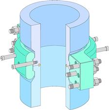
Figure 21-14 Clamp Hub [10]
Clamp hubs are often used for subsea connections, because they are small and have a reduced number of bolts to handle, install, and tension. They can, however, be difficult to disconnect on occasion. Since the clamp hubs are pulled together by the tensioning of the bolts (wedging the clamp halves on the tapered hub profile), residual stress and friction resists removal of the clamp halves, even with the bolts removed. Divers often have to hammer or use a special tool, to strip the clamp halves of the hubs, particularly if they have been subsea for a considerable length of time. The characteristics of clamp hubs are summarized as follows:
• The clamping device preloads two hubs as the device is tightened.
• A metal gasket is compressed between the two hubs to create a seal.
• It can be made up by divers or ROV-operated tools
• It is faster to make up than a bolted flange because it has fewer bolts.
• Hubs must be closely aligned before makeup. Rotational alignment is not critical.
21.3.3 Collet Connector
Collet connectors are the most widely used for jumper spool style connections. The connection principle is similar to that for a hub and clamp except that a series of longitudinally segmented collets replaces the clamp. The collets are activated by an annular locking cam ring. The cam ring slides axially along the collet length to either open or close the connector. The driving angle on the cam ring is typically self-locking to prevent incidental unlocking of the connector. A collet connector consists of a body and hub around in which individual “fingers” or collets are arranged in a circular pattern and attached to the body, engaging the hub to form a fully structural connection as shown in Figure 21-15.

Figure 21-15 Pair of Collet Connectors [10]
The engagement between the hub and collets is either mechanically or hydraulically actuated. Funnels or guide posts provide coarse alignment for the mating hubs. After the collet connector is landed, an ROV installs the hot stab and provides hydraulic power to the stroking cylinders, pulling the hubs together at a controlled rate. The open collets provide initial makeup alignment to protect the metal seal. The standard design accommodates up to ±2° angular misalignment and ±1.5–in. axial offset. Once the hubs are mated, hydraulic collet actuating cylinders close the collet fingers to complete the connection. The collets impart a preload that gives the connection the same strength characteristics as the pipe. The seal is pressure tested after makeup via the ROV control panel. The characteristics of collet connectors are summarized as follows:
21.3.4 Dog and Window Connector
Dog and window flowline connectors are similar in principle to standard wellhead connectors where a number of “dog” segments are collapsed into a corresponding groove in the mating hub to lock the connection. The dogs are captured by “windows” within the connector assembly. The number of “dog” segments varies between manufacturers and can be as simple as a longitudinal cut in a fully circumferential ring. A locking piston is driven forward to collapse the dogs, setting the seal, and preloading the connection.
Figure 21-16 illustrates a typical dog and window connector. Its characteristics are summarized as follows:
• The locking dogs held in a window of the connector body are driven inward around a hub by an actuator ring.
• A metal gasket is compressed between the body and hub to create a seal.
• It functions by means of integral hydraulics or by an ROV-operated tool.

Figure 21-16 Dog and Window Connector [10]
21.3.5 Connector Design
The sealine connector choice and subsequent design should consider factors such as water depth, intervention method, type of connection point, sealine installation method, and misalignment tolerance compatibility with the alignment method. In addition, the choice and design of the connector can be influenced by the factors discussed next.
21.3.5.1 Connector Stresses
Residual stresses in the line itself and the sealine connector resulting from a particular alignment method and the additional axial movement required for end connection should be analyzed in conjunction with operating stresses to determine if the combined stress is within allowable limits.
21.3.5.2 Makeup Requirements
Makeup requirements for connectors should be reviewed to ensure that (1) the connector will deform or deflect the gasket to result in a seal; (2) there is enough preload in the connector to offset the installation and operating loads, which could otherwise break the gasket seal; and (3) there is enough axial clearance and access for seal replacement.
The sealine connector design should be such that after makeup it will not lose its sealing capability under cyclic pressures, temperatures, or natural vibration loading and design external loads.
21.3.5.3 Testing
The sealine connectors should be tested in plant to the hydrostatic test pressure stipulated for the sealine. In some cases, the connector may be part of and tested with the subsea facility. In such cases the connector should be tested to the hydrostatic test pressure stipulated for the subsea facility. If TFL (through flow line) is specified, each made-up connector should be drifted in accordance with API RP 17C [11]. Additional in-plant testing may be required to verify makeup preloads, fit, and functional performance of locking devices and hydraulic actuation devices.
The end-connector equipment is designed to provide some testing means to verify that the gasket has formed an adequate seal and the connector has been fully actuated or clamped together after it has been installed in subsea. In the evaluation of the connection methods, the following factors should be considered:
• Ruggedness or resistance to damage;
• Template piping interface fabrication difficulty;
To choose the connection method, the criterion is assigned to each factor according to its importance. Each connection method is ranked against the other methods on a scale from one to three within each criterion.
21.4 Design and Analysis of Rigid Jumpers
21.4.1 Design Loads
The design parameters used to analyze a rigid pipe jumper are:
• Working pressure (external hydrostatic pressure not considered);
• Temperature of the product inside the pipe, which may constitute derating the minimum yield strength of the per code;
• Insulation thickness and density required to prevent hydrate formation;
The design of the jumper system should take into account all loads, which may be imposed as a result of the following issues:
• Fabrication, assembly, and testing loads;
• Installation, including keelhauling, cross hauling, lowering to seabed, and landing. The jumper system will be assumed filled with water during deployment;
• Fabrication and measurement tolerances;
• Thermal and pressure loads, including effect of thermal/pressure cycling;
• Flowline operational loads (flowline end movement due to pressure, temperature, etc.);
• Subsidence loads (differential settlement);
• Vibration fatigue (from unsteady flow or VIVs from currents);
• Other operation-induced loads, including drill riser/BOP movement to tree/well jumper during workover.
21.4.2 Analysis Requirements
The jumper analysis should consider the analyses discussed next as a minimum.
21.4.2.1 Tolerance Analysis
A tolerance analysis should be performed to determine maximum allowable tolerances between mating components and subassemblies. It demonstrates that repeatable interfaces can be achieved and that connectors are fully interchangeable with mating hubs. It also determines the optimum jumper geometry for meeting functional requirements.
21.4.2.2 ROV Access Analysis
The contractor should perform an ROV accessibility analysis to demonstrate that the ROV has clear access to all ROV panels, mechanical overrides, hydraulic hot stabs, position indicators, jumper connections, etc.
21.4.2.3 Loading Analysis
The design must be confirmed through analysis of the following loading conditions:
• Transportation: Transportation criteria should be determined during the detailed design phase. The jumpers should be analyzed for transportation to the field.
• Offshore lifting: Analyses should be performed with appropriate load factors taking into account the dynamics of the installation vessel.
• Installation: An installation analysis should be performed.
• Thermal expansion: All thermal expansion loads should be considered to establish design loads for the manifold structure and the jumper system.
• Local stress analyses: Local stress analyses should be carried out for all joints, lifting points, and high stressed welds.
21.4.2.4 Thermal Analysis
A thermal analysis should be performed to confirm the expected time required to reach hydrate formation temperature in the jumper system. The analysis must include the jumper and the connector assembly.
21.4.3 Materials and Corrosion Protection
A coating system should be used for protection against corrosion. Careful attention should be given to the grounding of subassemblies to maintain continuity throughout the jumper connection system. The use of dissimilar metals in the system should be avoided.
21.4.4 Subsea Equipment Installation Tolerances
Tie-in connections are either vertical or horizontal based on system selection. Designed for water depths exceeding 10,000 ft (3000 m) and working pressures to 15,000 psi, all jumpers or spool pieces should be installed using guideline-less techniques as shown in Figure 21-17. Jumpers or spool pieces are installed after onshore construction and testing to mate to previously installed equipment, based on subsea metrology data. The installation tolerances of the subsea equipment may not exceed the tolerance of 2 degrees off verticality for any vertically oriented hub. Installation tolerances should be determined from the tolerance analysis of the well and flowline jumpers.

Figure 21-17 Rigid Jumper Installation
21.5 Design and Analysis of a Flexible Jumper
Figure 21-18 shows a 4-in. flexible jumper used to connect a subsea tree and manifold. The flexible jumper has found wide application as a connector between subsea structures. Flexible jumpers can be used to connect trees and pipelines (PLET) or manifolds. Its flexibility allows the connection to be made such that one side of the connection has sufficient movement.

Figure 21-18 Flexible Jumper between Tree and Manifold [12]
Figure 21-19 and 21-20 show, respectively, typical Oil States Industries (OSI) and Vetco Gray (VG) jumper gooseneck assemblies and components of a flexible jumper.

Figure 21-19 Typical Oil States Industries Jumper Gooseneck Assembly of a Flexible Jumper

Figure 21-20 Typical Vetco Gray Jumper Gooseneck Assembly of a Flexible Jumper
In the following sections, jumper in-place analyses and installation analyses are detailed for a GoM project.
21.5.1 Flexible Jumper In-Place Analysis
21.5.1.1 Allowable Jumper Loads for Jumper In-Place Analysis
The allowable jumper loads for a jumper in-place analysis are affected by the following issues:
• Maximum tension of flexible jumper. To ensure the integrity of supporting structures and the collet connectors of subsea structures, the horizontal tension should be limited to a maximum value (for example, 5 kips). The jumper loads and moments due to the maximum horizontal tension should be below the allowable limits.
• The minimum allowable bend radius should not below 1.25 × MBR (minimum bend radius).
• The flexible jumper should experience a positive bottom tension at all times (i.e., no axial compressive load is permitted).
• The induced maximum jumper loads should ensure the integrity and stability of adjacent structures at all times.
21.5.1.2 Analysis Methodology
During installation, and throughout the design life of jumpers, loads will be transferred from the jumpers to the PLET collet connector and manifold structures. The global static analysis is performed to ensure the integrity of jumpers during installation and operating conditions, and to assess the induced load transfer from jumpers to the adjacent structures.
The jumper static design process includes the design steps shown in the flowchart of Figure 21-21.

Figure 21-21 Typical Static Application Design Flowchart
Figure 21-22 shows the flowchart for system configuration design. Based on the flowchart, the following sections describe the analysis methodology adopted during the system configuration design.

Figure 21-22 Flowchart for System Configuration Design
Static Jumper Analysis
All static analyses are 2D or 3D load cases, which account for all functional loads. In the analysis of the flexible jumper, the following external forces are considered:
Free-End Catenary Analysis
The free-end catenary analysis is performed to define the gooseneck angle. The term free-end refers to the top end of the jumper, which is fixed at a predetermined elevation although it is free to rotate according to the natural catenary configuration of the jumper. The free-end catenary analysis is performed for the operating condition, which is the long running load case that the jumper will experience during its design life.
For each jumper, the free-end catenary analysis assumes that the lower end of the jumper is resting on the seabed under a constant horizontal bottom tension. The predetermined elevation of the top end reflects the supporting structure height, with the nodal rotational degree of freedom unrestrained to allow the top end of the jumper to follow the natural catenary configuration of the free hanging string. For a range of bottom tension, the above analytical modeling allows study of jumper behavior to establish a range of touchdown locations and associated gooseneck angles. Based on this study, the gooseneck angle can be optimized to meet loading requirements. Based on the optimized gooseneck angle, the nominal bottom tension is defined for the operating condition.
In-Place Jumper Analysis
The in-place jumper analysis is performed to ensure that the gooseneck angle defined in the free-end catenary analysis provides a favorable solution for all other loading conditions. The in-place jumper analysis is also performed to provide a range of bottom tensions for which the integrity of the jumper and the supporting structure is maintained.
Based on the axial soil resistance, it is concluded that jumper lengths, in most cases, are not long enough to fully or partially restrain the jumper in the longitudinal direction. Any variation in axial tension, therefore, is anticipated to freely travel from the first end to the second end of the jumper. For this reason, it is recommended that the entire jumper, including first- and second-end elevations, be modeled when performing in-place analysis.
As minimum the following three extreme cases are investigated:
The near position is defined as the loading direction that results in the touchdown point (TDP) moving toward the supporting structure. In this situation, bottom tension is at a minimum and the jumper bend radius at the touchdown location is approaching the MBR criteria limitation. The far position is defined as the loading direction that results in the TDP moving away from the supporting structure. For this load case, the minimum bend radius usually occurs at the jumper/end-fitting connection interface. The induced moment and top tension are high for this loading condition. The transverse loading direction results in the TDP moving in the out-of-plane direction to the jumper.
The following criteria are used to establish jumper extreme positions:
• The minimum allowable bend radius should not below 1.25 × MBR.
• The flexible jumper should experience a positive bottom tension at all times (i.e., no axial compressive load is permitted).
• The induced maximum jumper loads should ensure the integrity and stability of adjacent structures at all times.
• A pipe rigidity transition zone of 1.5 × OD should be assumed after the jumper/end-fitting interface.
Jumper Curve Stability Analysis
The jumper stability analysis for the most conservative residual on-bottom tension will be performed to evaluate the minimum stable curve radius.
A lateral stability check is performed for each lateral bend using the following relationship:
![]()
where
Flexural Anchor Reaction Length Prior to Bend
The jumper curve stability analysis described above ensures jumper stability along the curve, during the laying operation. However, prior to a lateral bend, adequate anchorage is required to initiate the bend. Depending on the lateral jumper/seabed soil resistance, and the bend radius, a straight section of flexible pipe is defined to resist the induced moment and reaction loads at the bend tangential point. This straight section is referred to as the flexural anchor reaction (FAR) length and is evaluated using the following relationship:
![]()
where
21.5.2 Flexible Jumper Installation
The finite element program Orcaflex is commonly used to simulate the flexible jumper installation. The software is developed by Orcina Ltd. The following installation steps should been analyzed in the installation analysis:
The main parameters of the analysis and the items that should be investigated are:
• Wave height – constant throughout the analysis;
• Wave period – constant throughout the analysis;
• Wave type – Stokes fifth-order waves may be used in the analysis for conservatism;
• Current – assumed to be constant throughout the analysis;
• Vessel heading is maintained at 180 degrees or head seas, unless noted otherwise;
• Layback range (horizontal distance from overboard point to TDP);
Data required for the installation analysis include:
21.5.2.1 Design Criteria
The installation design criteria for a flexible jumper are listed below. The installation analysis is performed to ensure that these criteria could be safely and effectively achieved.
• MBR of flexible jumpers must not be exceeded.
• Tension at the PLETs and manifolds should not exceed a given value, for example, 5 kips.
• The bending moment (BM) applied to the BRs must remain within allowable limits.
• Connector hub angle must remain ±4° of vertical when connecting.
• Maximum load on the lifting adapter should not be exceeded.
• Load capacity of the cranes should not be exceeded.
• Maximum load on the A&R wire should be limited to allowable value, for example, 45 tonne.
21.5.2.2 Installation Steps
The installation steps for a flexible jumper for the project in the deep water of the GoM are given to show the procedure used for an installation analysis.
Step 1: Lowering of the Jumper
Analysis starts off with the jumper attached to crane hooks and hanging over the side of the vessel. This is the position from which the crane wires begin to pay out equally on both sides to begin lowering the jumper into the water. Figure 21-23 shows the lowering of the first end of the flexible jumper.

Figure 21-23 Lowering the First End of the Flexible Jumper
Step 2: Obtaining an Installation Configuration
This step involves lowering the jumper by simultaneously paying out equal amounts of crane wire on both sides into; the crane hooks reach a certain depth. After this depth is reached, only the crane wire attached to the first end is allowed to pay out further to lead into step 3. Figure 21-24 shows the installation configuration of a flexible pipeline after step 2.

Figure 21-24 Installation Configuration after Step 2
Step 3: Connecting to First-End
This step starts when the wire attached to the first end is paid out to reach the depth at which the first end can be connected to the applicable PLET/manifold. This is done while the other wire is held at the position where it was at the end of step 2. For some of the longer jumpers, the crane separation on board the vessel may need to be increased to around 70 m. The vertical separation of the two connectors has to be increased so as to assist in obtaining the vertical orientation of the connector being attached to the first end. Higher bending moments and curvatures are expected in the jumper due to this difference in elevation. Figure 21-25 shows the connection of the first end of the jumper to the PLET.

Figure 21-25 Connection of First End of the Jumper
Step 4: Connecting to Second-End
This step begins with the first end of the jumper being rigidly connected to the PLET/manifold. Thereafter, 10 m of the second-end crane wire is paid out (step 4, substep 1) to achieve touchdown and establish a layback. The subsequent steps involve paying out crane wire at the second end until the hub is within 10 m of its connection point and lowered further toward the second-end PLET/manifold in two steps (substeps 2 and 3), to be followed by the second end reaching the final connection position in the final step (substep 4). Figure 21-26 illustrates the finial step after the second end has been connected.

Figure 21-26 Finial Step after Second End Has Been Connected
REFERENCES
1. FMC Technologies, Subsea Tie-In Systems, http://www.fmctechnologies.com/subsea.
2. Oldfield T. Subsea, Umbilicals, Risers and Flowlines (SURF): Performance Management of Large Contracts in an Overheated Market; Risk Management and Learning. Houston, Texas: OTC 19676, Offshore Technology Conference; 2008.
3. G. Corbetta, D.S. Cox, Deepwater Tie-Ins of Rigid Lines: Horizontal Spools or Vertical Jumpers? 2001, SPE Production & Facilities, 2001.
4. Roveri FE, Velten AG, Mello VC, Marques LF. The Roncador P-52 Oil Export System Hybrid Riser at an 1800m Water Depth. Houston, Texas: OTC 19336, Offshore Technology Conference; 2008.
5. Technip, COFLEXIP Subsea and Topside Jumper Products, www.technip.com.
6. Cameron, Cameron Vertical Connection (CVC) System, http://www.c-a-m.com.
7. American Petroleum Institute. Specification for Subsea Wellhead and Christmas Tree Equipment. API Spec 17D 1992.
8. American Society of Mechanical Engineers. Pipe Flanges and Flanged Fittings. ASME/ANSI B16.5 1996.
9. International Organization for Standardization, Petroleum and Natural Gas Industries - Design and Operation of Subsea Production Systems - Part 4: Subsea Wellhead and Tree Equipment, ISO 13628-4, (1999).
10. Rose B. Flowline Tie-in Systems. Houston: SUT Subsea Awareness Course; 2008.
11. American Petroleum Institute. TFL (Through Flowline) Systems. second ed. API-RP-17C 2002.
12. Coleman E, Isenmann G. Overview of the Gemini Subsea Development. Houston, Texas: OTC 11863, Offshore Technology Conference; 2000.