Chapter 23
ROV Intervention and Interface
Contents
23.1. Introduction
23.2. ROV Intervention
23.2.1. Site Survey
23.2.2. Drilling Assistance
23.2.3. Installation Assistance
23.2.4. Operation Assistance
23.2.5. Inspection
23.2.6. Maintenance and Repair
23.3. ROV System
23.3.1. ROV Intervention System
23.3.1.1. ROV Categories
23.3.1.2. Topside Facilities
23.3.1.3. ROV Launch and Recovery Systems (LARS)
23.3.1.4. Umbilical and TMS
23.3.2. ROV Machine
23.3.2.1. Characteristics
23.3.2.2. Navigation System
23.3.2.3. Propulsion System
23.3.2.4. Viewing System
23.3.2.5. Manipulators
23.4. ROV Interface Requirements
23.4.1. Stabilization Tool
23.4.2. Handles
23.4.3. Torque Tool
23.4.3.1. Low Torque
23.4.3.2. High Torque
23.4.4. Hydraulic Connection Tool
23.4.5. Linear Override Tool
23.4.6. Component Change-Out Tool (CCO)
23.4.7. Electrical and Hydraulic Jumper Handling Tool
23.5. Remote-Operated Tool (ROT)
23.5.1. ROT Configuration
23.5.2. Pull-In and Connection Tool
23.5.3. Component Change-Out Tool
23.1 Introduction
As field developments move into deep water, numerous subsea intervention tasks have been moved out of reach of human direct intervention. Remote-operated vehicles (ROVs) and remote-operated tools (ROTs) are required to carry out subsea tasks that divers cannot reach. An ROV is a free-swimming submersible craft used to perform subsea tasks such as valve operations, hydraulic functions, and other general tasks. An ROT system is a dedicated, unmanned subsea tool used for remote installation or module replacement tasks that require lift capacity beyond that of free-swimming ROV systems [1, 2].
This chapter provides an overview of the state of the art for subsea remote intervention and vehicles, ROV technologies, and ROV capabilities and requirements for subsea operations.
23.2 ROV Intervention
The term subsea intervention refers to all activities carried out subsea. An intervention philosophy needs to be built before designing the interface for a subsea production system (SPS). The intervention philosophy normally focuses on the following questions:
• What kind of tasks will be done subsea?
• What methods will be used to complete these jobs?
• What are the requirements to complete the intervention activities?
The first question will be discussed in this section. For the second question, two intervention methods are commonly used in the subsea engineering: (1) ROVs for inspection, cleaning, and so on, and (2) ROTs for module replacement and subsea tie-in. The answer to the third question can be found in API and NORSOK rules [1, 2, 3, 4]. Generally, ROVs are used for these issues, which are detailed in the following sections:
23.2.1 Site Survey
A site survey has to be carried out before offshore activities such as drilling and installation to obtain the seabed’s precise bathymetry and properties.
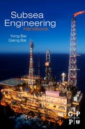
Detailed seabed mapping through precise bathymetry may be performed by a seabed reference system with differential pressure sensors and acoustic data transmission, which may be deployed and retrieved by an ROV. Seabed mapping can also be performed by an ROV carrying a multibeam echo sounder (MBE) or a side-scan sonar (SSS) as shown in Figure 23-1. A sub-bottom profiler (SBP) for sub-bottom profiling may be used to assess the quality of seabed properties for offshore installation foundation.
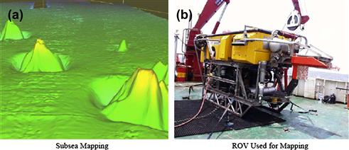
Figure 23-1 Seabed Mapping with a Workclass ROV [5]
23.2.2 Drilling Assistance
Drilling activities for production drilling and completion normally include:
• Deployment of acoustic units such as transponders or beacons by an ROV for surface or subsea positioning;
• Bottom survey by visual observation from a ROV with video and still cameras;
• Structure setting and testing (if needed) of permanent guide base (PGB), temporary guide base (TGB), Xmas tree, BOP, etc.;
• As-built (bottom) survey by ROV visual observation with supplemental equipment.
During the entire process, the observation tasks with video cameras (often with scanning sonar as supplemental “acoustic observation”) make up the majority of ROV drilling assistance. Tasks include conducting the bottom survey, monitoring the lowering of the structure and touching down, checking the structure’s orientation and level with a gyrocompass and bull’s-eye, respectively, and performing an as-built survey. Some necessary intervention work may have to be done with ROVs or ROTs during structure setting and testing:
• Acoustic transponder or beacon deployment and recovery;
• Debris positioning and removal from seabed and tree, including dropped objects;
• Structure position assistance with ROV pull/push;
• Guide wire deployment, recovery, and cutting during emergency conditions;
• Rigging (e.g., shackle connection and disconnection);
• Cement cleaning on guide base with brush or water jet;
• Valve operation with hydraulic torque tool or hydraulic stab-in;
• ROV-operable guide posts, replacement, and pin pull release;
• Control pod replacement if suitable for ROV (otherwise ROT);
23.2.3 Installation Assistance
The installation of a subsea production system from the water surface to the seabed can be divided into two parts:
• Subsea equipment installation (e.g., manifold deployment, landing);
• Pipeline/umbilical installation (e.g., initiation, normal lay and laydown).
The installation methods for subsea equipment may be divided into two groups. Large subsea hardware with weights over 300 tonne (metric ton) can be installed by a heavy lift vessel where the crane wire is long enough to reach the seabed and the crane is used to both put the equipment overboard and lower it. A soft landing to the seabed may be required using an active heave compensation system with the crane. Alternatively, it may be installed with a drilling tower on a drilling rig, which can have a lifting capacity up to about 600 tonne. For smaller subsea hardware (maximum approximately 250 tonne), a normal vessel equipped with a suitable crane for overboarding the hardware may be used. The vessel normally would not have a long enough crane wire to the seabed, so the hardware is transferred from the crane wire to a winch with a high capacity and a long enough wire for lowering the equipment to the seabed once the hardware passes through the splash zone. In both installation groups, ROVs are used for observation and verification and for engagement and release of guide wires and hooks.
Subsea structures are widely positioned underwater using the long baseline (LBL) method in which transducers used for position measuring, a gyrocompass for orientation measuring, a depth sensor for depth measuring may be mounted onto structure by package(s) that will be retrieved by the ROV. The orientation control may be assisted by the ROV, and the ROV has to verify via camera that the structure is aligned and level before the structure’s final set-down. ROVs may also be used to install chokes, multiphase meters, and subsea control modules. For seal pressure tests, ROVs can be used for hot stabbing.
ROVs can be used to assist in the installation of a dead anchor for pipeline/umbilical laying initiation. They can also be used to connect the pull-in line for J-tube or I-tube initiation. During normal installation and pipeline/umbilical laydown, the touchdown point is often monitored with ROVs in front and behind.
The connections between subsea production equipment and flowlines and subsea equipment and umbilicals may be completed through flying leads from the umbilical termination assembly (UTA) to the tree/manifold, well jumper from the tree to the manifold, jumper from the manifold to the PLET. The flying leads may be handled and pulled in by an ROV directly. Jumpers can be deployed from a vessel with spreader bar(s), and then positioned and connector actuated with the assistance of an ROV.
23.2.4 Operation Assistance
Main production activities normally include:
• Flow control by chokes and valves operated by hydraulic actuators through control pods and umbilicals or externally by ROV or ROT intervention;
• Monitoring of flow temperature and pressure by relevant measurement meters;
• Chemical and inhibitor injection for corrosion, waxing, and hydrate formation resistance;
• Flow separation of liquids, gases, and solids (filtering);
During the operation phase, ROVs are normally not required except for noncritical valve actuation and possibly intermittent status checks, taking samples, etc.
23.2.5 Inspection
Inspection may be needed on a routine basis for the structures expected to deteriorate due to flowline vibration, internal erosion, corrosion, etc. Inspection includes:
• General visual inspection, including cathodic measurements and marine growth measurements;
• Close visual inspection additionally requiring physical cleaning for close visual inspection, CP measurements, and crack detection by means of nondestructive testing (NDT);
• Detailed inspection including close visual inspection, crack detection, wall thickness measurements, and flooded member detection;
• Routine pipeline inspection including tracking and measurement of depth of cover for buried pipelines, which is also applicable for control umbilicals and power/control cables.
Cathodic protection (CP) potential measurements may be completed by CP probe as shown in Figure 23-2. This type of measurement is normally carried out by a workclass ROV.

Figure 23-2 Polatrak ROVII Tip-Contact CP Probe
(Courtesy of Deepwater Corrosion Services, Inc. [6])
Cleaning may be performed by an ROV with brushing tools or high-pressure wet jets and grit entrainment as shown in Figure 23-3.

Figure 23-3 Rotating Brush and Water Jetting Tool
(Part a courtesy of Specialist ROV Tooling Services, Inc. [7]; part b courtesy of Subsea 7 Inc. [8])
Crack detection may be performed by an ROV with magnetic particle inspection (MPI), eddy current, alternating current field measurement (ACFM) methods, etc.
23.2.6 Maintenance and Repair
Maintenance activities include repair or replacement of modules subject to wear. Maintenance is normally performed by retrieving the module to the surface and subsequently replacing it with a new or other substitute module.
Retrieval and replacement have to be anticipated during subsea equipment design. Some modules such as multimeters, chokes, and control pods are subject to removal and replacement. A completed replacement may have to be carried out due to the significant wear on or damage to nonretrievable parts of subsea equipment.
Due to the difficulty and expense of maintenance and repair, the operation may be continued with regular monitoring if the damaged module is not readily replaced and does not prevent production.
23.3 ROV System
23.3.1 ROV Intervention System
An ROV system used in subsea engineering, as shown in Figure 23-4, can be divided into the following subsystems:
• Control room on deck for controlling the ROV subsea;
• Workover room on deck for ROV maintenance and repair;
• Deck handling and deployment equipment, such as A-frame or crane/winch;
• Umbilical to power ROV subsea and launch or recover ROV;
• Tether management system to reduce the effect of umbilical movement on the ROV;

Figure 23-4 ROV System
(Courtesy SEAEYE)
23.3.1.1 ROV Categories
ROV can be divided into fives classes as summarized in Table 23-1.
Table 23-1. ROV Classes [4]

23.3.1.2 Topside Facilities
Suitable deck area and deck strength, external supplies, and ease of launch and recovery should be provided on deck for safe and efficient operation of ROVs.
ROV control stations vary from simple PC gaming joysticks to complex and large offshore control containers/rooms on the platform or vessel. The control stations contain video displays and a set of operator/ROV interface-controlling mechanisms. A typical control container consists of operator console, lighting, electrical outlet, fire alarm and extinguishers, etc.
23.3.1.3 ROV Launch and Recovery Systems (LARS)
The LARS consists of a winch, winch power unit, crane/A-frame with fixed block, and ROV guiding system.
Generally speaking, launch and recovery activities can be achieved by a simple rope with uplift force. However, to facilitate the deployment and recovery of the rope, a reel/drum is used, and a motor is usually used to rotate the reel and provide the uplift force. The motor may be either a hydraulic motor or an electromotor with/without a gear box used to reduce the rotary speed and increase the torque force. The system of motor, reel/drum, base frame, and other ancillary structures such as a brake and clutch is normally called a winch. A fixed block, sustained at the end of a crane boom/A-frame beam, is used to change the upward direction of the required winch force to a downward direction and position the winch on the lower structure, for example, the deck.
To restrain ROV motion while it is being lowered from the air to the water surface a LARS is used. This helps prevent, for example, damage to the umbilical by the bilge keel if side deployment is being used. The LARS may be equipped with a docking head, cursor, or guide rails, as shown in Figures 23-5, 23-6, and 23-7.

Figure 23-5 Snubber-Rotator Docking Head
(Courtesy of Saab Seaeye Ltd. [9])

Figure 23-6 Wire-Guided Cursor [10]

Figure 23-7 Guide Rail System [10]
23.3.1.4 Umbilical and TMS
One characteristic difference between an ROV and an autonomous underwater vehicle (AUV), is that the ROV has an umbilical that runs between the support vessel and the ROV to transport hydraulic/electronic power from the vessel to the ROV and information gathered from the ROV to the surface. The AUV, on the other hands, is a robot that travels underwater without tethering to the surface vessel/platform. An ROV is usually armored with an external layer of steel and has torque balance capacity. The diameter and weight of the umbilical should be minimized to reduce the drag force due to waves and currents as well as lifting requirements during launch and recovery of the ROV from the water to the surface. Normally the umbilical has a negative buoyancy, and the umbilical may be attached with buoyancy, for example, every 100 m (328.1m) to avoid entanglements between the umbilical and subsea equipment or the ROV itself during shallow-water operation.
A tether management system (TMS) is used to deploy the ROV for deepwater applications where the umbilical with negative buoyancy can launch and recover the TMS and ROV. The connection cable between the ROV and TMS can be an umbilical called a tether that has a relatively small diameter and neutral buoyancy. The TMS is just like an underwater winch for managing the soft tether cable. A TMS has two significant advantages:
1. ROVs can be moved more easily due to deleting the force implied by the umbilical, which may be the same as the flying resistance of the ROV itself in a water depth of 200 m (656.2 ft) and increase rapidly with increasing water depth.
2. There is no need to use the ROV’s own thrusters to get the ROV down to the working depth near the seabed. A powered TMS, i.e., installing some thrusters to TMS cages may be carried out to account for large drag force on TMS due to significant currents (e.g., current velocity of 1 to 1.5 knots) in some areas.
The TMS is designed to manage the tether and can be either attached to a clump weight, mainly for the observation ROV, or to a cage deployment system, as shown in Figures 23-8 and 23-9, mainly for workclass ROVs.

Figure 23-8 Top Hat Type TMS
(Courtesy DOF SUBSEA)

Figure 23-9 Side Entry Type TMS with ROV
(Courtesy SAAB)
23.3.2 ROV Machine
23.3.2.1 Characteristics
Configuration
Most workclass ROVs have a rectangular configuration and an open Al-based frame that supports and protects the thrusters for propulsion, underwater cameras for monitoring, lights and other instruments such as closed-circuit television for observation, the gyrocompass for heading detection, depth gauges for depth detection, an echo-sounding device for altitude detection, and scanning sonars for environment inspection.
Most ROVs are near neutral buoyancy underwater. They do have a little buoyancy to make sure the ROVs can float to the water surface during emergency conditions or if they break. An ROV moves downward with a vertical thruster. Generally, the buoyancy is provided by synthetic foam material above the Al-based ROV frame. An ROV’s weight is typically in the range from 1000 to 3500 kg. Examples can be seen from the table in Annex A of API RP 17H [1]. The higher buoyancy center and lower weight of gravity ensure that the ROV provides good stability performance.
Operation Depth
Traditionally, ROVs had been designed and built for operations in water depths of 100 to 1000 m (328 to 3280ft), primarily supporting drilling operations, including seabed surveys, water jetting, and seal ring installation, as well as providing light construction support and inspection work. These ROVs have payload capacities of around 250 kg with power ranging from 40 to 75 hp.
As the oil and gas industry has probed into deeper and deeper waters, demand has increased for ROVs that provide diverless solutions for such tasks as remote interventions and pipeline/umbilical tie-ins. Table 23-2 lists the operational water depths of typical ROVs.
Table 23-2. Operational Water Depth of Typical ROVs

Payload
The payload capacity of an ROV is limited by:
Payload capacities for typical ROVs are listed in Table 23-3.
Table 23-3. Payload Capacity of Typical ROVs

23.3.2.2 Navigation System
The navigation of ROV includes general navigation and accurate navigation. The deck reckoning method and hydroacoustic method are used for general navigation. The hydroacoustic method is the most widely used today via the LBL system, in which there is a responder array on the seabed, at least one transponder set on the ROV, and one receiver set on the vessel.
Accurate navigation is used to lead the ROV to the target object. A gyrocompass provides the ROV heading and a viewing system is used that comprises imaging sonar/low light cameras and lights. Normally the power of a subsea light is between 250 and 500 W. An ROV might also have 750 to 1000 W of power for large lights and 100 to 150 W of power for small lights. There is also a cubic TV to provide 3D object configurations, that is, to obtain data about target thickness and distance between the ROV and the target.
23.3.2.3 Propulsion System
The propulsion system for an ROV consists of a power source, controller for an electric motor or a servo-valve pack for a hydraulic motor, and thrusters to adjust the vehicle condition (trim, heel, and heading) and to propel the vehicle for navigating from the TMS to the work site, and vice versa.
Being the main part of an ROV propulsion system, the underwater thrusters are arranged in several ways to allow for proper maneuverability and controllability of the vehicle through asymmetrical thrusting and varying the amount of thrust. The thrusters need to be adequately sized for countering all of the forces acting on the vehicle, including hydrodynamic and workload forces. There are a wide range of thrusters from electrically powered to hydraulically powered. In general, electrical thrusters are used for smaller vehicles, while the hydraulic ones are used for larger and workclass vehicles. Typical electric and hydraulic thruster examples are shown in Figure 23-10. When selecting thrusters for an ROV, the factors of power, efficiency, pressure, flow, weight, size, and forward /reverse characteristics should be taken into account.

Figure 23-10 Typical Electric and Hydraulic Thrusters
(Courtesy of Sub-Atlantic [13])
23.3.2.4 Viewing System
A wide range of underwater video cameras are used in ROVs for viewing purposes, typically for navigation, inspection, and monitoring.
Camera image sensors include low-light silicon intensified targets (SITs), charge-coupled devices (CCDs), and HADs for high-definition images. Some cameras are equipped with LED lights providing illumination for close-up inspection and eliminating the need for separate lighting. Images captured by a camera are transmitted as video signals through the tether and umbilical to a video capture device on the water surface.
23.3.2.5 Manipulators
An ROV is normally equipped with two manipulators, one for ROV position stabilization, normally with a five -function arm, and the other for intervention tasks, normally with a seven-function arm. Manipulator systems vary considerably in size, load rating, reach, functionality, and controllability. They may be simple solenoid-controlled units or servo-valve-controlled position feedback units. The end of the arm is fitted with a gripper, usually consisting of two or three fingers that grasp handles, objects, and structural members for carrying out an activity or stabilizing the ROV.
23.4 ROV Interface Requirements
To facilitate subsea interventions such as drilling assistance, installation assistance, and inspection, maintenance, and repair (IMR) by ROVs, interfaces are introduced and produced for ROVs:
• Hydraulic work package and docking frame for the ROV itself;
• Hydraulic connector, valve override tool, and adapter for the ROV manipulator;
and also for subsea equipment to facilitate ROV application:
This section describes the requirements for the typical interfaces and is based primarily on API 17H [1].
23.4.1 Stabilization Tool
The stabilization of ROVs can be achieved in the following ways:
• Working platform, formed by utilizing part of the subsea structure;
• Suction cups, consisting of an arm attached to the ROV and a suction cup on the end of the arm which may be used when the ROV carries out manipulator operations such as cleaning, inspection, and individual valve operation;
• Grasping, which can be widely used for all items of subsea hardware;
• Docking, used with a single- or twin-docking tool deployment unit (TDU) together where the loading of a subsea equipment interface is not desirable. The receptacle is incorporated into the structure of the subsea equipment, whether as a separate bolted or welded-in unit, or incorporated as part of the subsea equipment.
Figure 23-11 shows grasping handles and Figure 23-12 shows a suction cup used for an ROV.

Figure 23-11 Grasping Handles

Figure 23-12 Suction Cup
(Courtesy of Canyon Offshore Inc. [14])
The interfaces should satisfy following requirements:
• Working platforms for ROVs should be flush and free from obstruction.
• The subsea structure should be a flat surface broadly adjacent to the task area for the use of a suction cup for stabilization purposes.
• Grasping intervention interfaces should be designed to withstand a minimum force of 2.2 kN (500 lbf) and a gripping force of 2.2 kN (500 lbf) applied from any direction.
• The docking probe should have a fail-safe release as shown in Figure 23-13 and overload limitation features.

Figure 23-13 Docking with Fail-Safe Locking [1]
23.4.2 Handles
Handles are the interface between tools such as torque tools or hot stabs and the ROV manipulators or ROV-mounted tool TDU. The interface configuration is illustrated in Figure 23-14.

Figure 23-14 Handles
The interface should satisfy following requirements:
• The stem of handles should be capable of resisting the maximum operational forces regardless of whether they are linear forces or rotary forces.
• Any out-of-line forces generated by the operator in linear applications have to be taken into account by the compliancy between the handle and the attachment to the tool.
• The handle should be marked to display the direction of movement of the handles to reduce the probability of damage.
The interface can be operated by an ROV-mounted tool TDU or manipulator.
23.4.3 Torque Tool
23.4.3.1 Low Torque
This interface provides for ROV operation of ball and needle valves, clamps, etc. The interface on the subsea equipment comprises a paddle or T-bar enclosed in a tubular housing, as shown in the following figures, which may be incorporated into a panel by bolting or welding, be free standing, or be made as part of the subsea equipment.
Figure 23-15 shows types A, B, and C low-torque interface receptacles. The interface should satisfy the following requirements:
• If the interface receptacle is incorporated into a panel, the panel should be flush with the docking face.
• The interface should be manufactured from material with a minimum tensile strength of 450 MPa (65,300 psi) so that it can operate at the specified torques, but the engineer is free to specify other materials where different load conditions exist.
• Protection from marine growth and corrosion will be necessary in most environments, so consideration should be given to the use of corrosion-resistant materials or appropriate coatings.

Figure 23-15 Types A, B, and C Low-Torque Interface Receptacles
The interface tool of a low-torque tool can be operated by an ROV-mounted tool TDU or manipulator as shown in Figure 23-16.

Figure 23-16 Sketch of Torque Tool Operated by an ROV
23.4.3.2 High Torque
High-torque interfaces provide for the ROV operation of tree valves, clamps, satellite control module (SCM) lockdown, shackle release, etc.
The interface comprises a square driving stem enclosed in a tubular housing, as shown in Figure 23-17, which can be incorporated into a panel by bolting or welding, be free standing, or be made as part of the subsea equipment.

Figure 23-17 High-Torque Interface Receptacle
The interface should satisfy the following requirements:
• If the interface receptacle is incorporated into a panel, the panel should be flush with the docking face.
• The interface should be manufactured from material with a minimum tensile strength of 450 MPa so that it can be operated at the specified torques.
• Protection from marine growth and corrosion are necessary in most environments, so the use of corrosion-resistant materials or appropriate coatings should be considered.
The interface tool for a high-torque tool, as shown in Figure 23-18, can be operated by an ROV-mounted tool TDU or manipulator.

Figure 23-18 High-Torque Tool per API 17D
(Courtesy of Fugro-imp ROV Ltd. [15])
23.4.4 Hydraulic Connection Tool
The hot stab/hydraulic connection tool interface provides for ROV typical operation of valve actuation, seal and connection testing, chemical injection, planned or emergency release, and fluid collection. The interface comprises male and female mating halves, as show in Figure 23-19. The connection allows pressurization between two isolated sections separated by seals.
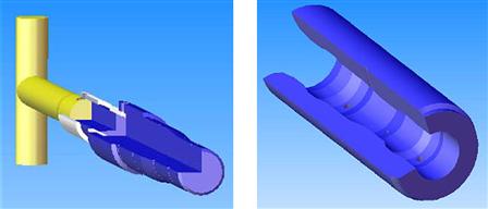
Figure 23-19 Male and Female Mating Halves of a Hot Stab Hydraulic Connection
The interface should satisfy the following requirements:
• The female receptacle, permanently mounted to the subsea system, should be manufactured with corrosion-resistant materials making it suitable for long-term immersion in seawater.
• The hot stab receptacle should be designed so that it does not fill with debris while not in use.
• The hot stab should have a flexible joint in the handle or stab to ease connection and disconnection activities.
• The receptacle should be self-sealing and watertight when uncoupled.
Figures 23-20 and 23-21 show two different types of hot stabs from different manufacturers. The interface tool can be operated by an ROV-mounted tool TDU or manipulator.

Figure 23-20 Hot Stab
(Courtesy of Nemo Offshore Pty Ltd. [16])

Figure 23-21 Hot Stab
(Courtesy of Tool Marine Technology Pty Ltd. [17])
23.4.5 Linear Override Tool
The ROV interface is primarily/typically for the ROV operation of hydraulic gate valves open after fail-safe closure, where it may be incorporated as part of the valve actuator. The linear override tool (LOT) interface tool is used to transmit the axial force to the stem of hydraulically actuated gate valves.
The interface on subsea equipment comprises a flange around a central stem, and it can be operated by the LOT handled by an ROV-mounted tool (e.g., ROV + TDU/manipulator).
Figure 23-22 shows a LOT made by Subsea 7. The linear actuator override tool (LAOT) has two discrete units: the tool itself and a tool carrier, which is used to deploy, lock (actuate the valve on subsea equipment at the same time), and retrieve the tool.

Figure 23-22 Linear Actuator Override Tool
(Courtesy of Subsea 7 Inc. [8])
Figure 23-23 shows an example of a standard linear override/push interface, which belongs to a type A interface. The interface has to satisfy the following requirements:
• The interface flange should endure the load induced by the maximum push force based on that required to open gate valves at full differential pressure and should be manufactured from material with a minimum tensile strength of 450 MPa to operate at the above loads.
• Protection from marine growth and corrosion is necessary in most environments, so the use of corrosion-resistant materials or appropriate coatings should be considered.
• It is important to check the stroke on the TDU to ensure sufficient clearance to fully make up the linear push device and to subsequently remove it.

Figure 23-23 Linear Push Type A Interface [1]
23.4.6 Component Change-Out Tool (CCO)
The ROV interface provides for ROV operation for the replacement of control pods, chokes, multiphase meters, etc. The ROV interface comprises two identical landing units, with one central lockdown receptacle and two weight receptacles including soft landing dampers or cover plates, as shown in Figure 23-24.

Figure 23-24 Component Change-Out Interface [1]
The ROV interface should satisfy the following requirements:
• The top face of the landing units should be positioned flush with or above the component lifting mandrel.
• Design loads for the landing units are particular to the component and should be evaluated on a case-by-case basis.
• The landing units may be structurally supported from either the structural framework or from the component base unit. The clearance required for weight transfer units should be taken into account the support arrangements.
The interface can be operated by an ROV-mounted tool or an ROT with ROV positioning, as shown in the Figure 23-25.
Figure 23-25 Component Change-Out Tool
(Courtesy of Subsea 7 Inc. [8])
23.4.7 Electrical and Hydraulic Jumper Handling Tool
This ROV interface provides for the ROV operation of installing the electrical flying lead, steel flying lead for transporting hydraulic fluid, and stab plate of the assembly of electric connectors or hydraulic couplings or both.
A single-connection interface handling tool can be operated by either a manipulator or TDU, whereas a multiple quick connect (MQC) stab plate can be operated by a TDU or a combination of manipulator and tool elevator. An oil-filled hose conduit connection interface can be used for a single connection.
The MQC interface should satisfy the following requirements:
23.5 Remote-Operated Tool (ROT)
23.5.1 ROT Configuration
An ROT system can be divided into the following subsystems, as shown in Figure 23-26:
• Deck handling and deployment equipment, such as A-frame or crane/winch;
• Controls room on deck to control the ROT subsea operation;
• Workover room on deck for ROT maintenance and repair;
• Umbilical/liftwire to power the ROT subsea and deploy or recover an ROV;

Figure 23-26 Sketch of ROT System
A ROT is mainly used for module replacement/change-out and flowline tie-in, both of which require a handling force larger than that of an ROV. ROTs are usually deployed on liftwires or a combined liftwire/umbilical, and the lateral guidance is powered by an umbilical with dedicated thrusters, ROV assistance, or guidewires.
The ROT system should provide for safe locking of the replacement module during handling, deployment, normal operation, and emergency conditions such as power failure.
There are three generations of ROT for tie-in tools:
23.5.2 Pull-In and Connection Tool
In this section, basic information about a pull-in and connection tool is provided. The pull-in and connection system includes the following main equipment:
• Connectors with seal assemblies. Connector type determines the required function of hydraulic supply, torque tools, integrated seal plate handling, and replacement tools;
• Pull-in and connection tools;
• Hubs, caps, and terminations;
• Pull-in porches/alignment structures for interfacing with subsea structures.
The collet connectors and clamp connectors are widely used connectors in the subsea industry. They are shown in the Figures 23-27 and 23-28. The stab hub (i.e., inboard hub) may be fixed on the subsea equipment. Figure 23-29 shows an example of a pull-in and connection tool.

Figure 23-27 Collet Connector
(Courtesy of Cameron international [18])

Figure 23-28 Clamp Connector
(Courtesy of Vector International [19])

Figure 23-29 Pull-In and Connection Tool
(Courtesy of Alker Solutions [20], Formerly Kvaerner)
The following are the main procedures required to make a connection:
• Rough alignment between inboard and outboard hubs, approached by pull-in tool or guiding funnel;
• Precise alignment after two hubs mate, completed by the connection tool;
• Connection by connecting tools (e.g., jacking screw operation by torque tools, and seal pressure test by ROV).
To prevent intrusion of saltwater, dirt, etc., into the hub sealing area, caps should be placed on the umbilical termination head before the connecting operation.
23.5.3 Component Change-Out Tool
A component change-out (CCO) tool is used to recover and reinstall subsea modules such as:
A CCO is often deployed by the guideline method or as a fly-to-place tool. It can be deployed to the seabed in an individual basket using the fly-to-place method, and the ROV with interface skid can dock onto the CCO and establish control of the CCO with, for example, the electrohydraulic stab plate connector. The ROV will then unlock the ROT from the basket, fly it to place, and dock onto the subsea structure. Figure 23-30 shows ROV-mounted tool deployment.

Figure 23-30 ROV Deployed ROT Sketch
This is the landing sequence for module replacement:
REFERENCES
1. American Petroleum Institute. Remotely Operated Vehicle (ROV) Interfaces on Subsea Production Systems. first ed. API-RP-17H 2004.
2. American Petroleum Institute. Remotely Operated Tool (ROT) Intervention System. first ed. API- RP-17M 2004.
3. Norwegian Technology Centre, Remotely Operated Vehicle Services, Rev 1, NORSOK standard U-102, (2003).
4. Norwegian Technology Centre, Subsea Intervention Systems, Rev 2, NORSOK standard U-007, (1998).
5. Gert JR. Challenges and Experience in ROV-based Deepwater Seabed Mapping. Houston, Texas: OTC 13158, Offshore Technology Conference; 2001.
6. Deepwater Corrosion Services Inc, http://www.stoprust.com.
7. Specialist ROV Tooling Services Ltd., http://www.specialistrov.co.uk.
8. Subsea 7, http://www.subsea7.com.
9. Saab Seaeye Limited, http://www.seaeye.com.
10. Davis CI, Lallier EB, Ross CL. Protective Deployment of Subsea Equipment. Houston, Texas: OTC 15089, Offshore Technology Conference; 2009.
11. Schilling Robotics, LLC. http://www.schilling.com.
12. SMD Robotics Ltd. http://www.smd.co.uk.
13. Sub-Atlantic. http://www.subatlantic.co.uk.
14. Canyon Offshore Inc. http://www.helixesg.com.
15. Fugro-ImpROV Ltd. http://www.improvltd.co.uk.
16. Nemo Offshore Pty Ltd. http://nemo-offshore.com.au.
17. Tool Marine Technology Pty Ltd. http://www.tmtrov.com.au/index.asp.
18. Cameron International Corporation. http://www2.c-a-m.com/index.cfm.
19. Vector International. http://www.vectorint.com/.
20. Alker Solutions. http://www.akersolutions.com/Internet/default.htm.