
The (Non) Standard TV Signal
Converting a three-dimensional moving image into a video signal requires a method of accurately translating light into electricity and then back into an image viewed on a TV monitor. This translation involves adopting a standard signal with a method of synchronization of line and frame repetition at the point of production, transmission and reception/video replay. There are many variables in the way this translation is accomplished:
![]() The number of lines in the picture and the number of pictures per second in monochrome television broadcasting were historically chosen to be compatible with the frequency of the AC power supply. There were 50 Hz countries and 60 Hz countries and so there arose over time two major scanning standards of 625 line/50 frames per second and 525 line/59.94 frames per second.
The number of lines in the picture and the number of pictures per second in monochrome television broadcasting were historically chosen to be compatible with the frequency of the AC power supply. There were 50 Hz countries and 60 Hz countries and so there arose over time two major scanning standards of 625 line/50 frames per second and 525 line/59.94 frames per second.
![]() A further division was established with the introduction of colour when different regions of the world chose different colour encoding systems such as NTSC, PAL and SECAM.
A further division was established with the introduction of colour when different regions of the world chose different colour encoding systems such as NTSC, PAL and SECAM.
![]() The colour signal can be passed through the production chain either as a composite signal or as a component signal.
The colour signal can be passed through the production chain either as a composite signal or as a component signal.
![]() The aspect ratio of the broadcast image (the ratio of the width of the image to its height) added another variable with ratios varying between 4:3, 16:9 and 14:9. Also methods of transmitting film images with other aspect ratios were evolved.
The aspect ratio of the broadcast image (the ratio of the width of the image to its height) added another variable with ratios varying between 4:3, 16:9 and 14:9. Also methods of transmitting film images with other aspect ratios were evolved.
![]() The conversion of an analogue signal into a digital signal introduced other variables depending on the sampling rate and the degree of compression employed.
The conversion of an analogue signal into a digital signal introduced other variables depending on the sampling rate and the degree of compression employed.
There are therefore not one but many ‘standard signals’ depending on region, production requirements and recording format. Fortunately, a programme originating in one standard can usually be converted into another standard with minimum loss of quality. Conversion between aspect ratios, however, often requires either a compromise on ideal picture framing or viewing conditions or special provision when originating the image.
Subjectivity
Number of lines, interlace and frame rate, transmission system, design of the camera, compression and sampling all affect how accurately the viewer sees the original event. The TV monitor imposes its own restraints. All these factors including resolution, contrast range, colour rendering, etc. are dependent on engineering decisions, budget restraints and statuary control and regulation. The translation between light and electricity is therefore influenced by choice and at each stage of the process, subjective decisions are made. In one sense electronic engineering ‘standards’ are no more objective than programme production. Most of this manual is concerned with the subjective choices available in video acquisition.
The Television Scanning System
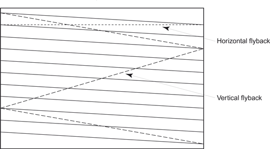
The television picture is made up of a series of lines which are transmitted with synchronizing pulses to ensure that the display monitor scans the same area of the image as the camera. In the PAL 625 line system, each of the 25 frames per second is made up of two sets of lines (fields) that interlace and cover different parts of the display. The picture is scanned a line at a time and at the end of each line a new line is started at the left-hand side until the bottom of the picture is reached. In the first field the odd lines are scanned after which the beam returns to scan the even lines. The first field (odd lines) begins with a full line and ends on a half line. The second field (even lines) begins with a half line and ends on a full line.
The Television Waveform
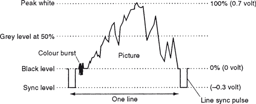
The waveform of the one-volt television signal divides into two parts at black level. Above black, the signal varies depending on the tones in the picture from black (0 V) to peak white (0.7 V). Below black, the signal (which is never seen) is used for synchronizing the start of each line and frame. A colour burst provides the receiver with information to allow colour signal processing.
How the Eye Sees Colour
There are three colour sensitive receptors in the eye which respond respectively to the primary colours of red, green and blue. All colours are seen by a mixture of signals from the three systems.
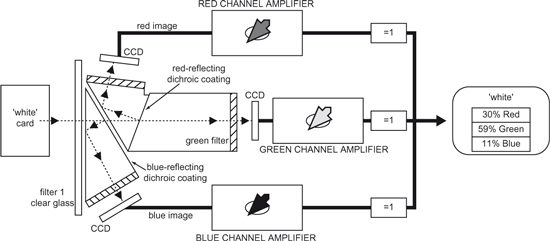
Colour television adopts the same principle by using a prism behind the lens to split the light from a scene into three separate channels (see figure opposite). The amplitude of these individual colour signals depends on the actual colour in the televised scene. Colours which are composed of two or more of these primary colours produce proportional signals in each channel. A fourth signal, called the luminance signal, is obtained by combining proportions of the red, green and blue signals. It is this signal which allows compatibility with a monochrome display. The amplitude of the signal at any moment is proportional to the brightness of the particular picture element being scanned.
White Balance
In colorimetry it is convenient to think of white being obtained from equal amounts of red, green and blue light. This concept is continued in colour cameras. When exposed to a white surface (neutral scene), the three signals are matched to the green signal to give equal amounts of red, green and blue. This is known as white balance. The actual amounts of red, green and blue light when white is displayed on a colour tube are in the proportion of 30% red lumens, 59% green lumens and 11% blue lumens. Although the eye adapts if the colour temperature illuminating a white subject alters (see topic White balance, page 106), there is no adaption by the camera and the three video amplifiers have to be adjusted to ensure they have unity output.
Colour Difference Signals
To avoid transmitting three separate red, green and blue signals and therefore trebling the bandwidth required for each TV channel, a method was devised to combine (encode) the colour signals with the luminance signal.
The ability of the eye to see fine detail depends for the most part on differences in luminance in the image and only, to a much smaller extent, on colour contrast. This allows the luminance (Y) information to be transmitted at high definition and the colour information at a lower definition resulting in another saving on bandwidth. Two colour difference signals are obtained, Er (red) – Ey (luminance) and Eb (blue) – Ey (luminance), by electronically subtracting the luminance signal from the output of the red and blue amplifiers. These two colour signals are coded into the luminance signal (Ey) and transmitted as a single, bandwidth-saving signal. Different solutions on how to modulate the colour information has resulted in each country choosing between one of three systems – NTSC, PAL and SECAM.
At the receiver, the signal can be decoded to produce separate red, green, blue and luminance signals necessary for a colour picture.
Additive Colour

A composite video signal is an encoded combined colour signal using one of the coding standards – NTSC, PAL or SECAM. This can be achieved using the luminance (Y) signal and the colour difference signals or red minus luminance (Er – Ey) and blue minus luminance (Eb – Ey). The signals are derived from the original red, green and blue sources and are a form of analogue compression.
A component video signal is one in which the luminance and the chrominance remain as separate components, i.e. separate Y, R–Y and B–Y signals.
Limitation of Analogue Signal
The analogue signal can suffer degradation during processing through the signal chain, particularly in multi-generation editing where impairment to the signal is cumulative. By coding the video signal into a digital form, a stream of numbers is produced which change sufficiently often to mimic the analogue continuous signal (see figure opposite).
The Digital Signal
Whereas an analogue signal is an unbroken voltage variation, a pulse coded modulated (PCM) digital signal is a series of numbers each representing the analogue signal voltage at a specific moment in time. The number of times the analogue signal is measured is called the sampling rate or sampling frequency. The value of each measured voltage is converted to a whole number by a process called quantizing. These series of whole numbers are recorded or transmitted rather than the waveform itself. The advantage of using whole numbers is they are not prone to drift and the original information in whole numbers is better able to resist unwanted change. The method of quantizing to whole numbers will have an effect on the accuracy of the conversion of the analogue signal to digital. Any sampling rate which is high enough could be used for video, but it is common to make the sampling rate a whole number of the line rate allowing samples to be taken in the same place on every line.
A monochrome digital image would consist of a rectangular array of sampled points of brightness stored as a number. These points are known as picture cells, or more usually abbreviated to pixels. The closer the pixels are together, the greater the resolution and the more continuous the image will appear. The greater the number of pixels, the greater the amount of data that will need to be stored, with a corresponding increase in cost. A typical 625/50 frame consists of over a third of a million pixels. A colour image will require three separate values for each pixel representing brightness, hue and saturation for each individual sampled point of the image. These three values can represent red, green and blue elements or colour difference values of luminance, red minus luminance and blue minus luminance. A moving image will require the three values of each pixel to be updated continuously.
Advantages of the Digital Signal
When a digital recording is copied, the same numbers appear on the copy. It is not a dub, it is a clone. As the copy is indistinguishable from the original there is no generation loss. Digital TV allows an easy interface with computers and becomes a branch of data processing.
Analogue to Digital

The continuously varying voltage of the TV signal (the analogue signal) is measured (or sampled) at a set number of positions per television line and converted into a stream of numbers (the digital signal) which alters in magnitude in proportion to the original signal.
Storing the signal as binary numbers (ones and zeros) has two advantages. It provides a robust signal that is resistant to noise and distortion and can be restored to its original condition whenever required. Secondly, it enables computer techniques to be applied to the video signal creating numerous opportunities for picture manipulation and to re-order the digital samples for standards conversion.
Why Compression is Needed
Compression, data reduction or bit-rate reduction, is the technique of filtering out some of the information that is contained in a digital video signal. By eliminating selected data, the signal can be passed through a channel that has a lower bit rate. The ratio between the source and the channel bit rates is called the compression factor. At the receiving end of the channel a decoder will attempt to restore the compressed signal to near its original range of values. A compressor is designed to recognize and pass on the useful part of the input signal known as the entropy. The remaining part of the input signal is called the redundancy. It is redundant because the filtered-out information can be predicted from what has already been received by the decoder. If the decoder cannot reconstruct the withheld data, then the signal is incomplete and the compression has degraded the original signal. This may or may not be acceptable when viewing the received image.
What Is Redundant?
Portions of an image may contain elements that are unchanging from frame to frame (e.g. the background set behind a newsreader). Considerable saving in the amount of data transmitted can be achieved if, on a shot change, all of the image is transmitted and then with each successive frame only that which alters from frame to frame is transmitted. The image can then be reconstructed by the decoder by adding the changing elements of the image to the static or unvarying parts of the image. The degree of compression cannot be so severe that information is lost. For example, even if the newsreader background set is static in the frame, a shadow of the newsreader moving on the background must be preserved even if the shadow is undesirable.
Motion Compensation
Passing on only the difference between one picture and the next means that at any instant in time, an image can only be reconstructed by reference to a previous ‘complete’ picture. Editing such compressed pictures can only occur on a complete frame. If there is significant movement in the frame there will be very little redundancy and therefore very little compression possible. To overcome this problem, motion compensation compression attempts to make even movement information ‘redundant’ by measuring successive areas of pictures which contain movement and producing motion vectors. These are applied to the object and its predicted new position reconstructed. Any errors are eliminated by comparing the reconstructed movement with the actual movement of the original image. The coder sends the motion vectors and the discrepancies along the channel to the decoder which shifts the previous picture by the vectors and adds the discrepancies to reproduce the next picture. This allows a saving in the amount of data that needs to be transmitted along a channel even with movement.

Quantizing
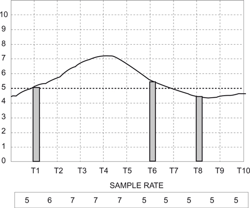
The data stored is transmitted as whole numbers. In the above diagram sample T1 = 5. T6 (although peaking at 5.5) would be stored as 5 and T8 (peaking at 4.5) would also be stored as 5.
![]() Aliasing: This is caused by the sampling frequency being too low to faithfully reproduce image detail.
Aliasing: This is caused by the sampling frequency being too low to faithfully reproduce image detail.
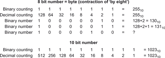
![]() Quantizing: In 8-bit video conversion there are 256 quantizing intervals because that is the number of codes available from an 8-bit number. With 10-bit conversion there are 1024 codes available.
Quantizing: In 8-bit video conversion there are 256 quantizing intervals because that is the number of codes available from an 8-bit number. With 10-bit conversion there are 1024 codes available.
A full frame of digital television sampled according to CCIR 601 requires just under 1 Mbyte of storage (829 kbytes for 625 lines, 701 kbytes for 525 lines).
Mos Capacitors
A MOS capacitor (see figure opposite) is a sandwich of a metal electrode insulated by a film of silicon dioxide from a layer of P-type silicon. If a positive voltage is applied to the metal electrode, a low energy well is created close to the interface between the silicon dioxide and the silicon. Any free electrons will be attracted to this well and stored. They can then be moved on to an adjacent cell if a deeper depletion region is created there.
The ability to store a charge is fundamental to the operation of the charge coupled device plus a method of transferring the charge.
Charge Coupled Device
If a photosensor replaces the top metal electrode, and each picture element (abbreviated to pixel) is grouped to form a large array as the imaging device behind a prism block and lens, we have the basic structure of a CCD camera. Each pixel (between 500 and 800 per picture line) will develop a charge in proportion to the brightness of that part of the image focused onto it. A method is then required to read out the different charges of each of the half a million or so pixels in a scanning order matching the line and frame structure of the originating TV picture. Currently there are three types of sensors in use, differing in the position of their storage area and the method of transfer.
![]() Frame transfer: The first method of transfer developed was the frame transfer (FT) structure. The silicon chip containing the imaging area of pixels is split into two parts. One half is the array of photosensors exposed to the image produced by the lens and a duplicate set of sensors (for charge storage) is masked so that no light (and therefore no build up of charge) can affect it. A charge pattern is created in each picture field which is then rapidly passed vertically to the storage area during vertical blanking. Because the individual pixel charges are passed through other pixels a mechanical shutter is required to cut the light off from the lens during the transfer.
Frame transfer: The first method of transfer developed was the frame transfer (FT) structure. The silicon chip containing the imaging area of pixels is split into two parts. One half is the array of photosensors exposed to the image produced by the lens and a duplicate set of sensors (for charge storage) is masked so that no light (and therefore no build up of charge) can affect it. A charge pattern is created in each picture field which is then rapidly passed vertically to the storage area during vertical blanking. Because the individual pixel charges are passed through other pixels a mechanical shutter is required to cut the light off from the lens during the transfer.
![]() An important requirement for all types of CCDs is that the noise produced by each sensor must be equivalent, otherwise patterns of noise may be discernible in the darker areas of the picture.
An important requirement for all types of CCDs is that the noise produced by each sensor must be equivalent, otherwise patterns of noise may be discernible in the darker areas of the picture.
![]() Interline transfer: To eliminate the need for a mechanical shutter, interline transfer (IT) was developed. With this method, the storage cell was placed adjacent to the pick-up pixel, so that during field blanking the charge generated in the photosensor is shifted sideways into the corresponding storage element. The performance of the two types of cell (photosensor and storage) can be optimized for their specific function although there is a reduction in sensitivity because a proportion of the pick-up area forms part of the storage area.
Interline transfer: To eliminate the need for a mechanical shutter, interline transfer (IT) was developed. With this method, the storage cell was placed adjacent to the pick-up pixel, so that during field blanking the charge generated in the photosensor is shifted sideways into the corresponding storage element. The performance of the two types of cell (photosensor and storage) can be optimized for their specific function although there is a reduction in sensitivity because a proportion of the pick-up area forms part of the storage area.
![]() Frame interline transfer: This type of CCD, as its name suggests, incorporates features of both the FT and the IT structures.
Frame interline transfer: This type of CCD, as its name suggests, incorporates features of both the FT and the IT structures.
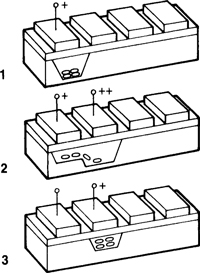
1: After a positive voltage (e.g. 5 V) is applied to the electrode, a low-energy well is created below the oxide/semiconductor surface, attracting free electrons.
2: If 10 V is applied to the adjacent electrode, a deeper low-energy well is created, attracting free electrons which now flow into this deeper bucket.
3: If the voltage on the first electrode is removed and the second electrode voltage is reduced to 5 V, the process can be repeated with the third cell. The charge can be moved along a line of capacitors by a chain of pulses (called a transfer clock) applied to the electrodes.
By replacing the electrode with a light-sensitive substance called a ‘photo-sensor’, a charge proportional to the incident light is transferred using the above technique.
The Hyper Had
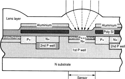
The Hyper HAD has a microlens positioned on each pixel which increases the light-capturing ability of each photosensor area, doubling the camera sensitivity.
Camera Matching
A basic requirement in multi-camera productions is that there are no mismatches of exposure or colour rendition when cameras are intercut. This is achieved by remotely controlling the aperture (affecting exposure) and colour adjustment of each camera by vision control where the output of each camera is compared, adjusted and matched. Built in ND (neutral density) filters and colour correction filters between lens and CCDs can also be switched in when required.
Iris
The remote control of the lens aperture (iris) on each camera is essential for correct exposure and to match cameras. Although it is possible on many studio programmes to balance lighting levels and therefore work with almost the same aperture on the majority of shots, there are many situations where large variations in lighting levels require constant adjustment of aperture to maintain correct exposure.
Gain (Master Gain)
The gain of the head amplifiers can be increased if insufficient light is available to adequately expose the picture. The amount of additional gain is calibrated in dBs, (see Glossary for definition of dBs). For example, switching in +6 dB of gain is the equivalent of opening one stop of the lens, which would double the amount of light available to the sensors. The extra gain in amplification is achieved by a corresponding decrease in the signal-to-noise ratio and therefore will increase the noise in the picture.
Black-Level Adjustment (Lift)
The black level in a picture can be adjusted to expand or crush the dark tones in an image. Its ‘correct’ setting is when black is reproduced as black rather than a dark shade of grey or dark grey is reproduced as black, but adjusting the level of what is reproduced as black can be a decision based on production requirements.
Detail Enhancement and Skin Tone Detail
In most video cameras, image enhancement is used to improve picture quality. One technique is to raise the contrast at the dark-to-light and light-to-dark transitions, to make the edges of objects appear sharper, both horizontally and vertically. This is done electronically by overshooting the signal at the transition between different tones to improve the rendering of detail. The degree of electronic manipulation of edge detail is variable but one limiting factor in the amount of enhancement that can be used is the adverse effect on faces. When pictures are ‘over-contoured’ skin detail can appear intrusive and unnatural; every imperfection is enhanced and becomes noticeable.
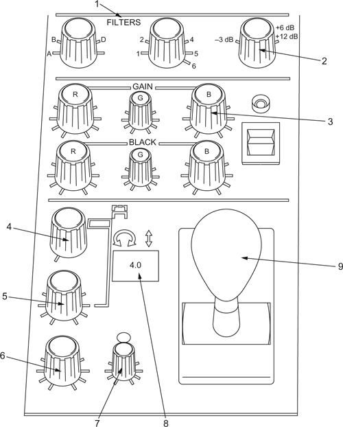
This is a typical operational control panel (OCP) for a full-facilities camera.
1. Remote control of filter wheels located between lens and light-splitting system (colour correction, neutral density and effects filters).
2. Master gain control; extra gain is used when operating in low light.
3. Gain and black trims, used for minor adjustment of colour gain and black level when matching pictures.
4. Auto/manual iris control.
5. Detail enhancement.
6. Contrast control, used to modify the ‘law’, i.e. to stretch/crush appropriate parts of the grey scale.
7. Range control, adjusts the range over which the joystick will operate, and selects the mean aperture.
8. Readout of lens aperture.
9. Joystick, the main operational control, has three functions.
Twist to adjust master black level.
Forward/back to open/close iris.
Depress to switch channel to preview monitor.
Gamma
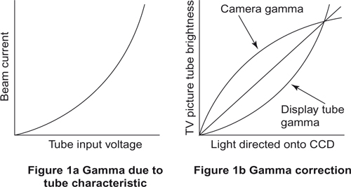
Although there can be considerable image manipulation during production, the picture the viewer will finally see is dependent on the characteristics of their TV set. The cathode ray display tube, however, has certain limitations. The television image is created by a stream of electrons bombarding a phosphor coating on the inside face of the display tube. The rate of change of this beam and therefore the change in picture brightness does not rise linearly, in-step with changes in the signal level corresponding to the changes in the original image brightness variations.
As shown in the Figure 1(a) graph opposite, the beam current, when plotted against the input voltage, rises in an exponential curve. This means that dark parts of the signal will appear on the tube face much darker than they actually are, and bright parts of the signal will appear much brighter than they should be. The overall aim of the television system is to reproduce accurately the original image and therefore some type of correction needs to be introduced to compensate for the nonlinear effect of the cathode ray tube beam. The relationship between the input brightness ratios and the output brightness ratios is termed the gamma of the overall system. To achieve a gamma of 1 (i.e. a linear relationship between the original and the displayed image – a straight line in Figure 1b graph) a correcting signal in the camera must be applied to compensate for the distortion created at the display tube. Uncorrected, the gamma exponent of the TV system caused by the display tube characteristics is about 2.4. Thus the camera’s gamma to compensate for the non-linearity of the TV system is about 0.44/0.45. This brings an overall gamma of approximately 1.1 (2.4 X 0.45) slightly above a linear relationship to compensate for the effect of the ambient light falling on the viewer’s display tube. There is the facility to alter the amount of gamma correction in the camera for production purposes. The application of gamma correction to the signal in the camera also helps to reduce noise in the blacks.
Linear Matrix
As detailed in ‘Colour’ (page 36), all hues in the visible spectrum can be matched by the mixture of the three primary colours, red, green and blue. In the ideal spectrum characteristics of the three primary colours, blue contains a small proportion of red and a small negative proportion of green. Green contains a spectral response of negative proportions of both blue and red. It is not optically possible to produce negative light in the camera but these negative light values cannot be ignored if faithful colour reproduction is to be achieved. The linear matrix circuit in the camera compensates for these values by electronically generating and adding signals corresponding to the negative spectral response to the R, G and B video signals. This circuit is placed before the gamma correction so that compensation does not vary due to the amount of gamma correction.
Linear Matrix

The values chosen for the linear matrix determine the colour relationships and opinions of what the mix of RBG should be varies depending on which images need to be optimally presented by the broadcaster. Usually the broadcast organization chooses the skin tones of presenters as the basis for the choice of matrix values. As the exact value of skin tones differ from country to country, each region has its own preferred rendering of skin-tone values, resulting in large variations among broadcast organizations. Digital cameras have a range of user-selectable possible matrices.
The table show the different colour matrices chosen by the European Broadcast Union, the BBC (UK), RAI (Italy) and a standard camera matrix. The reds in the RAI choice are more brilliantly rendered than those of the others. The BBC matrix tends to produce softer colour rendition, while the EBU matrix is constructed to minimize the objective colour differences between a broad range of colours.