
Introduction
There are many advantages in recording items or complete programmes on location. Often the subject of the insert is the location or activity and must be recorded as found. The disadvantage is that away from base, a unit must be self-sufficient in all that is required to complete the assignment. Before travelling to a site it is worthwhile, if you are inexperienced, to make time to check over all equipment that will be needed to complete the job. Experience will teach you that frequently the shoot is not as the brief or script predicts and a few equipment ‘extras’ will enable you to salvage what could have been a wasted journey.
Pool Equipment
Some camera users work or study with organizations where there is a pool of shared or hired-in equipment. They may be less experienced and may operate with several different cameras of unknown serviceability. To work with an unfamiliar camera each day is much more exacting than to work with a predictable and familiar camera. A start-of-day check on pool cameras and mounts is vital to eliminate problems with the equipment before arriving at the location.
Inventory Check
Check that every item of equipment is there. Location work can be rushed and it is not unknown on a quick ‘wrap’ for a small item to be overlooked and left behind. Check the main equipment and then the smaller items such as power and connecting cables for mains adaptor, wet weather cover, dichroic filter on battery lamp, etc. And remember to check over the equipment you bought to a location when you leave the location.
Battery and Electronic Checks
Clip on battery and turn the power switch to on. Check the state of charge of the battery indicated in the display window. Find out when they were on charge and in what condition they were before the charge. A battery that has been charged and not used for several days may not remain fully charged. Individual cells discharge at different rates and the battery may have become unequalized. It may not respond to a fast charge before you leave. Run the camera up and carry out a quick check of all the main controls. Make certain that each switch is set to the mode you wish to operate in.
Mechanical Checks
Check all mechanical parts for security and stability. A common problem is the interface between tripod adaptor and the pan/tilt head. Check that the tripod adaptor on the pan/tilt head is suitable for the camera and that the locking mechanism will hold the camera secure.
Flange-back (commonly called back focus) is the distance from the flange surface of the lens mount to the image plane of the pick-up sensor. Each camera type has a specific flange-back distance (e.g. 48 mm in air) and any lens fitted to that camera must be designed with the equivalent flange-back. There is usually a flange back adjustment mechanism of the lens with which the flange-back can be adjusted by about ±0.5 mm. It is important when changing lenses on a camera to check the flange-back position is correctly adjusted and to white balance the new lens.
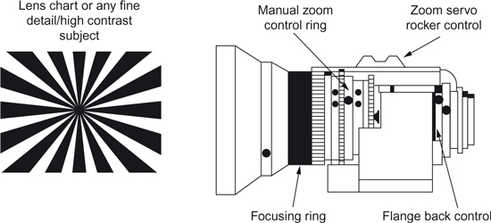
- Open lens to its widest aperture and adjust exposure by adding ND filters or adjusting shutter speed.
- Select the widest lens angle.
- Adjust for optimum focus with the flange back control on the lens.
- Zoom the lens in to its narrowest angle on an object at a distance from the camera and adjust the zoom focus for optimum sharpness.
- Zoom out and repeat steps 2–4 of the above procedure until maximum sharpness is achieved at both ends of the zoom range.
- Lock off the flange-back control taking care that its sharpest focus position has not been altered.
Remove lens and inspect rear element and filter wheel for finger marks or scratches. Refit lens if clean. Check that auto-iris and auto-zoom are set to AUTO position if you wish to operate in this mode.
A front-of-lens screw-in filter such as an ultraviolet (UV) is the best protection for the front element of a zoom. The cost of replacement, if damaged, is insignificant compared to the cost of repairing or replacing the zoom front element. Lens tissue and breathing on the front-of-lens filter is the most common and the simplest method of removing rain marks or dust. Dirt and dust can be removed with an air blower or wiped off gently with a lens brush. Never vigorously rub the lens surface or damage to the lens coating may result. Where there is oil, fingerprints or water stains, apply a small amount of commercial lens cleaner to a lens tissue and clean in a circular movement from centre to edge of lens.
Moisture and Humidity
Protect lens from driving rain. Dry off lens casing with a cloth and front element with lens tissue. Place lens in a plastic bag overnight, with a desiccant such as silica gel. Check that the HUMID indicator is off in display window before inserting tape cassette.
Menu
Most digital camera functions and parameters such as gain, shutter, etc., can be programmed from a computer menu displayed in the viewfinder or external monitor. Each set of memorized variables is called a scene file and is stored either on a removable memory card or in a memory system integral to the camera. There are usually four or five different categories of file available.
- A default scene file containing values which have been preset by the manufacturer. This should be selected when using a camera following on from other users.
- There may be a scene file which has been customized by an organization for a group of users such as students (e.g. a standard zebra setting).
- A blank scene file can save any adjustment to the camera variables displayed on the menu. It is advisable to name the file to indicate its application (e.g. J. Smith File or Preset Studio, etc.).
- An engineering file may be locked to prevent accidental adjustment to crucial camera settings (e.g. Linear Matrix Table).
- There is usually a self-diagnostic programme which checks the camera/recorder electronics and reports on the status of each section.
Check the menu settings and select default or factory setting if another user of the camera has reprogrammed the set-up card.
Viewfinder: Brightness and Contrast
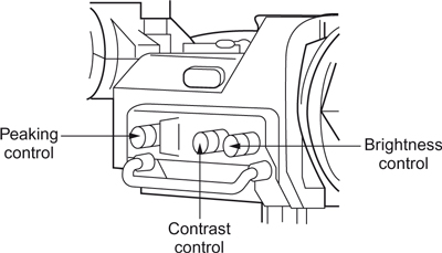
The monocular viewfinder is the first and often the only method of checking picture quality for the camcorder cameraman. The small black and white image has to be used to check framing, focusing, exposure, contrast and lighting. It is essential, as the viewfinder is the main guide to what is being recorded, to ensure that it is correctly set up. This means aligning the brightness and contrast of the viewfinder display. Neither control directly affects the camera output signal. Indirectly, however, if the brightness control is incorrectly set, manual adjustment of exposure based on the viewfinder picture can lead to under or over-exposed pictures. The action of the brightness and contrast controls therefore needs to be clearly understood.
![]() Brightness: This control alters the viewfinder tube bias control and unless it is correctly set-up the viewfinder image cannot be used to judge exposure. The brightness control must be set so that any true black produced by the camera is just not seen in the viewfinder.
Brightness: This control alters the viewfinder tube bias control and unless it is correctly set-up the viewfinder image cannot be used to judge exposure. The brightness control must be set so that any true black produced by the camera is just not seen in the viewfinder.
If, after a lens cap is placed over the lens and the aperture is fully closed, the brightness is turned up, the viewfinder display will appear increasingly grey and then white. This obviously does not represent the black image produced by the camera. If the brightness is now turned down, the image will gradually darken until the line structure of the picture is no longer visible. The correct setting of the brightness control is at the point when the line structure just disappears and there is no visible distinction between the outside edge of the display and the surrounding tube face. If the brightness control is decreased beyond this point, the viewfinder will be unable to display the darker tones just above black and distort the tonal range of the image. There is therefore only one correct setting of the brightness control which once set, should not be altered.
![]() Contrast: The contrast control is in effect a gain control. As the contrast is increased the black level of the display remains unchanged (set by the brightness control) whilst the rest of the tones become brighter. This is where confusion over the function of the two viewfinder controls may arise. Increasing the contrast of the image increases the brightness of the image to a point where the electron beam increases in diameter and the resolution of the display is reduced. Unlike the brightness control, there is no one correct setting for the contrast control other than an ‘over-contrasted’ image may lack definition and appear subjectively over-exposed. Contrast is therefore adjusted for an optimum displayed image which will depend on picture content and the amount of ambient light falling on the viewfinder display.
Contrast: The contrast control is in effect a gain control. As the contrast is increased the black level of the display remains unchanged (set by the brightness control) whilst the rest of the tones become brighter. This is where confusion over the function of the two viewfinder controls may arise. Increasing the contrast of the image increases the brightness of the image to a point where the electron beam increases in diameter and the resolution of the display is reduced. Unlike the brightness control, there is no one correct setting for the contrast control other than an ‘over-contrasted’ image may lack definition and appear subjectively over-exposed. Contrast is therefore adjusted for an optimum displayed image which will depend on picture content and the amount of ambient light falling on the viewfinder display.
![]() Peaking: This control adds edge enhancement to the viewfinder picture as an aid in focusing and has no effect on the camera output signal.
Peaking: This control adds edge enhancement to the viewfinder picture as an aid in focusing and has no effect on the camera output signal.
Tape problems
The tape is manufactured to a high tolerance and requires care in handling. Check for tape slack and tighten reels before loading. Do not force the cassette into the VTR. When battery voltage is almost below the level required to operate, the cassette can be removed. With some formats, when the voltage falls below this point, the cassette cannot be ejected or the cassette holder closed.
Batteries
For many years nickel cadmium (Ni-Cd) batteries have been the standard power for portable video cameras. With the growth of portable computers and mobile phones, new battery technologies using nickel metal hydride (NiMH) and rechargeable lithium have been developed but at present NiCad batteries form the main proportion of professional video batteries in use. The camera/recorder is normally powered by a 13.2 V or 14.4 V nickel-cadmium rechargeable battery which is clipped to the back of the recorder. There are a range of different capacity batteries available to give extended running times or several batteries can be grouped together and worn on a belt.
Capacity
The capacity of a battery is often rated in ampere-hours, which is the maximum current flow (amps) in one hour before the battery is completely discharged. A more useful measure is how long a specific battery will run a specific make of camera. The nominal run time is calculated by multiplying the battery voltage by its ampere hour rating to determine a watt hour figure which is then divided by the power rating of the camera/recorder, e.g. a 12 volt/5 AH battery = 12 (volts) x 5 (AH) = 60 watt hours which will give a 2.5 hours run time for a camera drawing 24 watts (60 ÷ 24). For the same camera, a 14.4 volt/5 AH battery = 14.4 x 5 (AH) = 72 watt hours will give a 3 hour run time (72 ÷ 24).
Battery Voltage Range
Another crucial camera specification is the operating voltage range. Most cameras will specify a minimum voltage below which the camera will not operate and an upper voltage beyond which, operating the equipment will cause damage or trigger the power breaker. The value of this power figure is stated, for example, as 12 V (–1 +5) which means that the camera will function over the voltage supply range of 11 V through to 17 V.
Tape problems that can occur include:
![]() Head clogging caused by a build up of invisible metal particles. You must use a cleaning cassette to maintain tape path performance but do not exceed the recommended timetable of cleaning as excessive cleaning can shorten the life of the head.
Head clogging caused by a build up of invisible metal particles. You must use a cleaning cassette to maintain tape path performance but do not exceed the recommended timetable of cleaning as excessive cleaning can shorten the life of the head.
![]() Tape dropout can be caused by imperfections in the coating and by worn heads with insufficient contact between tape and head. After considerable use, the head may need replacing. Also, any part of the recorder that the tape comes into contact with (guides and rollers, etc.) should be periodically checked and cleaned.
Tape dropout can be caused by imperfections in the coating and by worn heads with insufficient contact between tape and head. After considerable use, the head may need replacing. Also, any part of the recorder that the tape comes into contact with (guides and rollers, etc.) should be periodically checked and cleaned.
![]() Excessive humidity or low humidity can cause problems. Although the tape is manufactured with a built in lubricant to reduce tape wear, high humidity causes stiction and increases the risk of head clogging. At lower humidities electro-static charging will be more pronounced resulting in greater attraction of dust and an increase in dropout. Allow tapes to acclimatize if they have been subject to extremes of temperature or humidity.
Excessive humidity or low humidity can cause problems. Although the tape is manufactured with a built in lubricant to reduce tape wear, high humidity causes stiction and increases the risk of head clogging. At lower humidities electro-static charging will be more pronounced resulting in greater attraction of dust and an increase in dropout. Allow tapes to acclimatize if they have been subject to extremes of temperature or humidity.
![]() Moisture condensation on the drum assembly may occur if the camera is moved from a cold to a warm location or if the unit is used in a very humid place (e.g. an enclosed swimming pool). This may cause the tape to stick to the head and damage head and tape. Avoid this occurring by removing cassette when changing from cold to hot locations and, with the power on, check that the HUMID indicator in the display window does not light. Do not insert cassette until the HUMID indicator light goes off.
Moisture condensation on the drum assembly may occur if the camera is moved from a cold to a warm location or if the unit is used in a very humid place (e.g. an enclosed swimming pool). This may cause the tape to stick to the head and damage head and tape. Avoid this occurring by removing cassette when changing from cold to hot locations and, with the power on, check that the HUMID indicator in the display window does not light. Do not insert cassette until the HUMID indicator light goes off.
![]() Cinching of the tape is caused by badly adjusted playback recorders which abruptly stop and cause several layers of tape to slip and bunch between themselves. Remember that the tape from the camera is the master tape and irreplaceable. It should not be used to repeatedly view the day’s shooting. Transfer to VHS for production viewing and guard the use of the master tape until it arrives in post production.
Cinching of the tape is caused by badly adjusted playback recorders which abruptly stop and cause several layers of tape to slip and bunch between themselves. Remember that the tape from the camera is the master tape and irreplaceable. It should not be used to repeatedly view the day’s shooting. Transfer to VHS for production viewing and guard the use of the master tape until it arrives in post production.
Safety Hazards When Charging a Battery
![]() Cold temperature charging: The fast charging of a cold battery is one of the most dangerous hazards associated with NiCad batteries and can result in a violent explosion. When a NiCad is fast charged at temperatures below +5°C (+41°F), the internal charging reaction cannot proceed normally and a significant portion of the charge current can be diverted into producing highly explosive hydrogen gas. A spark can ignite this gas causing an explosion that can turn the battery into a grenade. Cold batteries must be allowed to reach room temperature before being placed on a charger.
Cold temperature charging: The fast charging of a cold battery is one of the most dangerous hazards associated with NiCad batteries and can result in a violent explosion. When a NiCad is fast charged at temperatures below +5°C (+41°F), the internal charging reaction cannot proceed normally and a significant portion of the charge current can be diverted into producing highly explosive hydrogen gas. A spark can ignite this gas causing an explosion that can turn the battery into a grenade. Cold batteries must be allowed to reach room temperature before being placed on a charger.
![]() Fire hazards: NiCad batteries and chargers have been identified as the source of several fires and toxic smoke incidents over the years. One major TV network instructed their cameramen that batteries must not be charged in their hotel bedrooms. Most of these incidents are connected to fast chargers that failed to recognize when a battery reached full charge. The continuing current produces heat and eventually smoke or fire. This can be avoided by the use of a thermal fuse in the power circuit which will disconnect the battery from the charger if dangerous temperatures are detected. A similar fire hazard can also occur if there is a mismatch between the charger and battery on a slow charge. Always provide for air circulation around batteries and do not charge batteries in a bag or flight case.
Fire hazards: NiCad batteries and chargers have been identified as the source of several fires and toxic smoke incidents over the years. One major TV network instructed their cameramen that batteries must not be charged in their hotel bedrooms. Most of these incidents are connected to fast chargers that failed to recognize when a battery reached full charge. The continuing current produces heat and eventually smoke or fire. This can be avoided by the use of a thermal fuse in the power circuit which will disconnect the battery from the charger if dangerous temperatures are detected. A similar fire hazard can also occur if there is a mismatch between the charger and battery on a slow charge. Always provide for air circulation around batteries and do not charge batteries in a bag or flight case.
![]() Physical shock: If a battery is internally damaged by physical impact or being accidentally dropped, internal wires can be short circuited and become red hot elements causing the battery to burst into flames. Take every precaution to avoid subjecting batteries to violent physical impact.
Physical shock: If a battery is internally damaged by physical impact or being accidentally dropped, internal wires can be short circuited and become red hot elements causing the battery to burst into flames. Take every precaution to avoid subjecting batteries to violent physical impact.
![]() Most of the above hazards can be avoided or eliminated by using an interactive charger that continuously interrogates the battery while charging.
Most of the above hazards can be avoided or eliminated by using an interactive charger that continuously interrogates the battery while charging.
Health and safety legislation obliges you to take reasonable care of your own health and safety and that of others who may be affected by what you do or fail to do. You also have a responsibility to co-operate, as necessary, to ensure satisfactory safety standards. If you comply with the requirements for safety and something goes wrong, then your employer will be held to account. If you fail to comply, you may lose any claim for compensation for injury and could even be prosecuted as an individual. What you must do is:
![]() Follow the safety requirements and any instructions you are given, especially in relation to emergencies (e.g. know the location of fire exits).
Follow the safety requirements and any instructions you are given, especially in relation to emergencies (e.g. know the location of fire exits).
![]() Ask for further information if you need it and report accidents (or a near miss!), and any dangerous situations or defects in safety arrangements.
Ask for further information if you need it and report accidents (or a near miss!), and any dangerous situations or defects in safety arrangements.
![]() Do not interfere with or misuse safety systems or equipment, or engage in horseplay that could be dangerous.
Do not interfere with or misuse safety systems or equipment, or engage in horseplay that could be dangerous.
![]() Work within the limits of your competence, which means a knowledge of best practice and an awareness of the limitations of one’s own experience and knowledge.
Work within the limits of your competence, which means a knowledge of best practice and an awareness of the limitations of one’s own experience and knowledge.
Assessing Risk
The key to good, safe working practices is to assess any significant risk and to take action to eliminate or minimize such risks. The procedure is:
![]() identify precisely what is required in the production
identify precisely what is required in the production
![]() identify any potential hazards in that activity
identify any potential hazards in that activity
![]() identify the means by which those risks can be controlled.
identify the means by which those risks can be controlled.
The key terms in risk assessment are:
![]() Hazard – the inherent ability to cause harm.
Hazard – the inherent ability to cause harm.
![]() Risk – the likelihood that harm will occur in particular circumstances.
Risk – the likelihood that harm will occur in particular circumstances.
![]() Reasonably practicable – the potential improvement in safety is balanced against the cost and inconvenience of the measures that would be required. If the costs and inconvenience do not heavily outweigh the benefits, then the thing is reasonably practicable and should be done.
Reasonably practicable – the potential improvement in safety is balanced against the cost and inconvenience of the measures that would be required. If the costs and inconvenience do not heavily outweigh the benefits, then the thing is reasonably practicable and should be done.
![]() Residual risk – the risk remaining after precautions have been taken.
Residual risk – the risk remaining after precautions have been taken.
An Example
It is proposed to shoot from a camera hoist near overhead power lines. The power lines are a hazard. Touching them could result in death. What is the likelihood (risk) that harm will occur in particular circumstances? There may be the risk of a high wind blowing the hoist onto the power lines. Is the weather changeable? Could a high wind arise? What is reasonable and practical to improve safety? The obvious action is to reposition the hoist to provide a usable shot but eliminate all risk of it touching the power lines. As weather is often unpredictable, the hoist should be repositioned as the costs and inconvenience do not heavily outweigh the benefits. There remains the residual risk of operating a camera on a hoist which can only be partially reduced by wearing a safety harness.
A check list of potential location safety hazards
![]() Boats: It is essential to wear life lines and life-jacket when operating on a boat or near water such as on a harbour wall.
Boats: It is essential to wear life lines and life-jacket when operating on a boat or near water such as on a harbour wall.
![]() Confined spaces: Check the quality of air and ventilation when working in confined spaces such as trench, pipes, sewer, ducts, mines, caves, etc.
Confined spaces: Check the quality of air and ventilation when working in confined spaces such as trench, pipes, sewer, ducts, mines, caves, etc.
![]() Children are a hazard to themselves. When working in schools or on a children’s programme, check that someone is available and responsible to prevent them touching or tripping over cables, floor lamps, camera mountings, etc.
Children are a hazard to themselves. When working in schools or on a children’s programme, check that someone is available and responsible to prevent them touching or tripping over cables, floor lamps, camera mountings, etc.
![]() Explosive effects and fire effects must be regulated by a properly trained effects operator and especial care should be taken with those effects that cannot be rehearsed.
Explosive effects and fire effects must be regulated by a properly trained effects operator and especial care should be taken with those effects that cannot be rehearsed.
![]() Excessive fatigue is a safety problem when operating equipment that could cause damage to yourself or others and when driving a vehicle on a long journey home after a production has finished.
Excessive fatigue is a safety problem when operating equipment that could cause damage to yourself or others and when driving a vehicle on a long journey home after a production has finished.
![]() Fork lift trucks must have a properly constructed cage if they are to carry a cameraman and camera.
Fork lift trucks must have a properly constructed cage if they are to carry a cameraman and camera.
![]() Lamps:All lamps should have a safety glass/safety mesh as protection against exploding bulbs. Compact source discharge lamps must always be used with a UV radiation protective lens. Lamps rigged overhead must be fitted with a safety bond. Check that lamp stands are secured and cabled to avoid being tripped over and that they are securely weighted at the base to prevent them being blown over.
Lamps:All lamps should have a safety glass/safety mesh as protection against exploding bulbs. Compact source discharge lamps must always be used with a UV radiation protective lens. Lamps rigged overhead must be fitted with a safety bond. Check that lamp stands are secured and cabled to avoid being tripped over and that they are securely weighted at the base to prevent them being blown over.
![]() Location safety: In old buildings, check for weak floors, unsafe overhead windows, derelict water systems and that the electrical supply is suitable for the use it is put to. Check the means of escape in case of fire and the local methods of dealing with a fire. Check for the impact of adverse weather and in remote locations, the time and access to emergency services.
Location safety: In old buildings, check for weak floors, unsafe overhead windows, derelict water systems and that the electrical supply is suitable for the use it is put to. Check the means of escape in case of fire and the local methods of dealing with a fire. Check for the impact of adverse weather and in remote locations, the time and access to emergency services.
![]() Noise:High levels of location noise (machinery, etc.), effects (gunshots, explosions) as well as close working to foldback speakers can damage hearing. Stress will be experienced attempting to listen to talkback with a very high ambient noise. Wear noise-cancelling headsets. If wearing single sided cans, use an ear plug in the unprotected ear.
Noise:High levels of location noise (machinery, etc.), effects (gunshots, explosions) as well as close working to foldback speakers can damage hearing. Stress will be experienced attempting to listen to talkback with a very high ambient noise. Wear noise-cancelling headsets. If wearing single sided cans, use an ear plug in the unprotected ear.
![]() Stunt vehicles: Motor vehicles travelling at speed involved in a stunt are likely to go out of control. Leave the camera locked-off on the shot and stand well away from the action area in a safe position agreed with the stunt-coordinator.
Stunt vehicles: Motor vehicles travelling at speed involved in a stunt are likely to go out of control. Leave the camera locked-off on the shot and stand well away from the action area in a safe position agreed with the stunt-coordinator.
![]() Filming from a moving vehicle: Camera must be either securely mounted or independently secured on safety lanyards. Operators should be fitted with seat belts or safety harness attached to safety lines securely anchored.
Filming from a moving vehicle: Camera must be either securely mounted or independently secured on safety lanyards. Operators should be fitted with seat belts or safety harness attached to safety lines securely anchored.
![]() Roadside working: Wear high visibility gear and get the police to direct traffic if required. Police may give permission for a member of the crew to direct traffic but motorists are not obliged to obey such instructions.
Roadside working: Wear high visibility gear and get the police to direct traffic if required. Police may give permission for a member of the crew to direct traffic but motorists are not obliged to obey such instructions.
ENG format cameras
A variety of digital recording formats have been developed particularly the upgrading of hitherto domestic digital video recording formats to facilitate cheaper and less complex cameras/recorders to match the different production requirements of video acquisition.
Betacam Format Specification
The picture is recorded on a ½ in Beta tape cassette using two adjacent video heads. The luminance signal (Y) is recorded on one track and on the other track the chroma consists of a compressed time division multiplex of the colour difference signals (red – Y and blue – Y). Two audio longitudinal tracks are recorded at the top of the tape with longitudinal control and time code tracks at the bottom of the tape. Betacam SP recording on metal particle tape provides two additional audio FM channels recorded with the chrominance signal. They allow improved sound quality but cannot be edited independently of the video and must be layed-off to be edited.
Digital Betacam
Digital working provides greater control over the look of the picture with the ability to alter gamma, knee point, skin tone, detail enhancement, matrix, etc. Also the ability for precise colour matching in a multi-camera shoot using a wide range of gamma curves programmed into the camera. Linear matrix coefficients can be varied and two sets of the coefficients stored in memory. Additional control over image appearance is now possible with such variables as horizontal detail enhancement to match scene content, detail clip level to avoid excessive highlight detail and stepped lines along slanted picture edges. A skin tone detail function allows selective reduction to be applied to face tones. This can reduce or eliminate facial imperfections while maintaining detail enhancement to the rest of the image.
Betacam SX
The Betacam SX format has the following additional features. Auto-tracing white (on B position) which will white balance when moving between different colour temperature light (e.g. moving between interior and exterior). Its automatic selected value cannot be stored. Pressing ‘return’ on the lens during a recording places a ‘good shot’ marker on the tape which can be picked up by the edit machine. The camera operator can identify and code up to 198 selected shots while shooting. These codes are stored on the tape and can be read-out during the edit. In addition to the selectable three gain positions positioned on the side of the SX range of cameras, there is an instant turbo gain button providing an immediate 36 dB gain (equal to 6 stops). Time code regeneration facility (in record run) can pick up on the existing recorded time code of any tape placed in the camera. Dockable Betacam SX recorders can be used with analogue cameras.
The DV format was originally intended for the domestic camcorder market as the DV format cameras did not meet the basic ENG requirements of operational features and ruggedness. The picture quality, however, was good enough for broadcasters to use the format in productions that required small, inexpensive lightweight kit.
DVCPRO and DVCAM are upgrades of the DV format primarily designed for news acquisition. The two formats have an improved recording specification and a number of broadcast operational facilities not found on consumer DV cameras. The camera/recorders are smaller, lighter and cheaper, and with less power consumption than previous ENG formats, coupled with smaller cassettes, allow longer recording times. The lightweight cameras allow easier handling in ENG work and have the ability to provide colour playback. With low power consumption, a two-machine editor can provide rapid, portable editing on location and stories can be put to air more quickly.
![]() Digital-S: Digital-S uses the same size half-inch tape and cassette as S-VHS and records on metal particle tape. Certain Digital-S studio VTRs can replay standard analogue S-VHS tapes allowing continuing access to previous S-VHS tape libraries. Digital-S uses 4:2:2 processing with a video data rate of 50 Mega bits per second with a 3.3:1 compression. The half-inch width tape allows 2 linear audio cue-tracks for audio access in edit shuttle and 4 digital audio (16 bit, 48 kHz) tracks and for 2 lines for uncompressed video for closed captioning. Up to 104 minutes of material can be recorded.
Digital-S: Digital-S uses the same size half-inch tape and cassette as S-VHS and records on metal particle tape. Certain Digital-S studio VTRs can replay standard analogue S-VHS tapes allowing continuing access to previous S-VHS tape libraries. Digital-S uses 4:2:2 processing with a video data rate of 50 Mega bits per second with a 3.3:1 compression. The half-inch width tape allows 2 linear audio cue-tracks for audio access in edit shuttle and 4 digital audio (16 bit, 48 kHz) tracks and for 2 lines for uncompressed video for closed captioning. Up to 104 minutes of material can be recorded.
![]() Disk camera: The Camcutter format records direct to disk in the camera/recorder. This allows certain edit functions to be performed in the camera. Whereas digital formats required downloading from tape to disk, the Camcutter’s FieldPak (a disk drive in the camera) can be removed and inserted into the desktop FieldPak adaptor and non-linear edited. Each FieldPak can be reused many thousands of times. The disk recording unit is available in two configurations: as an add-on to a suitable existing Ikegami camera or as an integrated single-piece camera/recorder unit.
Disk camera: The Camcutter format records direct to disk in the camera/recorder. This allows certain edit functions to be performed in the camera. Whereas digital formats required downloading from tape to disk, the Camcutter’s FieldPak (a disk drive in the camera) can be removed and inserted into the desktop FieldPak adaptor and non-linear edited. Each FieldPak can be reused many thousands of times. The disk recording unit is available in two configurations: as an add-on to a suitable existing Ikegami camera or as an integrated single-piece camera/recorder unit.
Disk recording allows the additional production facilities on camera of:
![]() RetroLoop: This facility constantly records in a pre-defined loop of time selectable from 15 to 60 seconds. When the record button is pressed, video/audio stored in the RetroLoop is kept as part of the new clip. This stored 15–60 seconds of material is added to the new shot.
RetroLoop: This facility constantly records in a pre-defined loop of time selectable from 15 to 60 seconds. When the record button is pressed, video/audio stored in the RetroLoop is kept as part of the new clip. This stored 15–60 seconds of material is added to the new shot.
![]() Intelligent recording: This facility allows immediate recording without cueingup blank tracks even during playback. The new data is written onto free tracks avoiding over-recording previous material. Automatic clip numbering on every separate shot/recording.
Intelligent recording: This facility allows immediate recording without cueingup blank tracks even during playback. The new data is written onto free tracks avoiding over-recording previous material. Automatic clip numbering on every separate shot/recording.
![]() Time lapse recording: This function enables intermittent recording at predetermined intervals for a predetermined period of time. Disk cameras can be preprogrammed to record one frame at predetermined intervals.
Time lapse recording: This function enables intermittent recording at predetermined intervals for a predetermined period of time. Disk cameras can be preprogrammed to record one frame at predetermined intervals.
![]() Lip-synching: Audio can be recorded while video is played back. While video is played, a pre-scripted narration can be recorded.
Lip-synching: Audio can be recorded while video is played back. While video is played, a pre-scripted narration can be recorded.
![]() Location control: Access to any desired point on the disk can be selected by use of camera report or time code without the need to shuttle. Simple editing can be done with the camera/recorder.
Location control: Access to any desired point on the disk can be selected by use of camera report or time code without the need to shuttle. Simple editing can be done with the camera/recorder.
![]() Erasing unwanted video: In camera, previous recordings may be reviewed and unnecessary clips deleted. This function enables only necessary scenes to be left on the disk. About 15–20 minutes (2.2 Gb) of recording time is normally attainable with a single FieldPak. Thirty minutes of record time is available on the higher density FieldPak.
Erasing unwanted video: In camera, previous recordings may be reviewed and unnecessary clips deleted. This function enables only necessary scenes to be left on the disk. About 15–20 minutes (2.2 Gb) of recording time is normally attainable with a single FieldPak. Thirty minutes of record time is available on the higher density FieldPak.
Processing of the output from the red, green and blue sensors is normalized to signal levels produced by a scene lit with tungsten lighting (3200 K). When the camera is exposed to daylight, it requires significant changes to the red channel and blue channel gains to achieve a ‘white balance’. Many cameras are fitted with two filter wheels which are controlled either mechanically, by turning the filter wheel on the left-hand side at the front of the camera, or by selecting the required filter position from a menu displayed in the viewfinder. The filter wheels contain colour correction and neutral density filters and possibly an effects filter. The position of the various filters varies with camera model.
Filter Selection
Set the filter selectors to match the colour correction filter appropriate to the light source and light intensity. A common combination of colour correction and neutral density filters are:
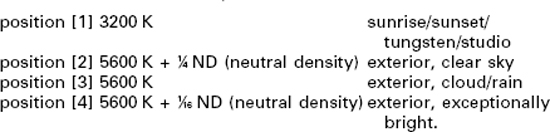
Neutral density filters are used when there is a need to reduce the depth of field or in circumstances of a brightly lit location. The 3200 K is a clear glass filter whereas a 5600 K filter (with no ND) is a minus blue filter to cut out the additional blue found in daylight. All colour correction filters decrease the transmission of light and therefore the minus blue filter cuts down the light (by approximately one stop) where most light is available – in daylight. A white balance is required after changing filter position.
To White Balance
To white balance, select the appropriate filter according to the lighting condition and fill the frame with a white object lit by the predominant subject illumination. Check that the gain is at 0 or as low as possible and that any contrast control facility is switched out.
There are usually two memory buttons associated with each filter. Select A or B on the white balance selector and set the IRIS to automatic iris control. Push the AUTO W/B BAL switch to WHT. The adjustment will be completed in about one second and the adjusted value will be stored in the A or B memory selected. If the white balance was unsuccessful the viewfinder may display a message such as ‘WHITE:NG’ – white balance no good – and an explanatory message. If you set the WHITE BAL selector to the PRST (preset) the white balance will be set to the factory-preset value of 3200 K if the filter position is set to the 3200 K filter position.
Peak white clippers: There are three peak white clippers, one in each colour channel, and their function is to limit any part of the scene that would produce a signal greater than a pre-set value. Their effect is to render all gradations in brightness above the ‘clip’ level as white – to burn out any overexposed parts of the picture. This can be difficult for the cameraman to see if his viewfinder is not correctly adjusted.
Knee

The ‘knee’, which is introduced into the camera head amplifiers, progressively compresses highlights which otherwise would be lost in the peak white clipper. It extends the camera’s response to a high contrast range but with some loss of linearity.
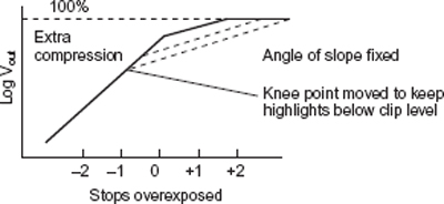
Variable Slope Highlight Control
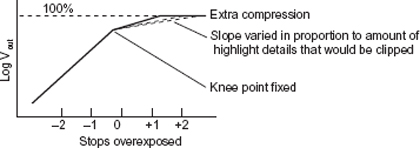
Variable knee Point Highlight Control
Contrast range
Every shot recorded by the camera/recorder has a variation of brightness contained within it. This variation of brightness is the contrast range of the scene. The relationship between the brightest part of the subject and the darkest part is the contrast ratio. Normally, exposure is adjusted to allow the contrast range of the scene to be accurately reproduced on the recording. The aim is to avoid losing any variation between shades and at the same time maintaining the overall scene brightness relationships.
Achieving the correct exposure for any specific shot therefore requires reproducing the detail in the highlights as well as in the shadows of the scene. Additionally, if a face is the subject of the picture then the skin tones need to be set between 70% and 75% of peak white (may be a wider variation depending on country and skin tones). Whereas the contrast ratios of everyday location and interiors can range from 20:1 to 1000:1, a video camera can only record a scene range of approximately 32:1. Peak white (100%) to black level (3.125%) is equivalent to 5 stops. The contrast range can be extended by compressing the highlights using a non-linear transfer characteristic when translating light into the television signal (see page 107). The amount of compression on the highlights can be further increased by switching in contrast control circuits. The result of recording a contrast range greater than the camera can handle is highlights of the scene will appear a uniform white – details in them will be burnt out and the darker tones of the scene will be a uniform black. The limiting factor for highlight detail in high contrast scenes is the peak white clipper circuits and the ‘knee’ of signal amplification in the camera.
Auto-Exposure
Exposure can be determined by using the auto-iris exposure circuit built into the camera or by manually using a light meter and the viewfinder picture, or using the zebra indicator in the viewfinder. Auto-exposure works by averaging the picture brightness and therefore needs to be used intelligently. In some cameras, different portions of the frame can be monitored and the response rate to the change of exposure can be selected. In general, expose for the main subject of the shot and check that the auto-iris is not compensating for large areas of peak brightness (e.g. overcast sky) in the scene.
Zebra Exposure Indicator
The zebra pattern is a visual indicator in the viewfinder when areas of the picture have reached a certain signal level. If the zebra exposure indicator is switched on, those elements of the image that are above this pre-set level are replaced by diagonal stripes in the picture. The cameraman can respond by closing the iris until part or all of the zebra diagonals have been removed.
Exposure and the Reduction in Contrast Range

The auto exposure system measures the range of subject brightness and sets an f-number which will reproduce a mid-tone grey at 50% of peak white. 50% of peak white is equivalent to the light from a subject with 18% reflectance.
Time code enables every recorded frame of video to be numbered. This allows precise identification when editing. There are two methods of recording the identification number.
Longitudinal Time Code
Longitudinal time code (LTC) is recorded with a fixed head on a track reserved for time code. It can be decoded at normal playback speed and at fast forward or rewind but it cannot be read unless the tape is moving as there is no replayed signal to be decoded. It is recorded once every frame as a series of pulses (binary digits) whose repetition rate changes according to whether it is recording 0s or 1s.
Vertical Interval Time Code
Vertical interval timecode (VITC) numbers are time-compressed to fit the duration of one TV line and recorded as a pseudo video signal on one of the unused lines between frames. It is recorded as a variation in signal amplitude once per frame as binary digits. 0 equals black and 1 equals peak white.
The 300/400 series Beta format cameras have the ability to insert VITC twice on two non-consecutive lines. They are factory-set to insert the VITC signal between lines 19 and 21 for PAL but there is provision for another choice of line position for VITC insertion independent of the first choice.
Code Word
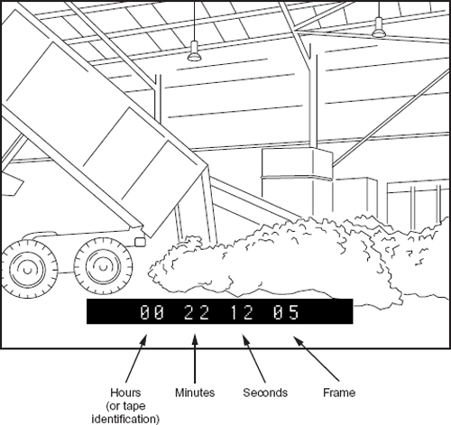
Every frame contains an 80 bit code word which contains ‘time bits’ (8 decimal numbers) recording hours, minutes, seconds, frames and other digital synchronizing information. All this is updated every frame but there is room for additional ‘user bit’ information.
User Bit
User bit allows up to 9 numbers and an A to F code to be programmed into the code word which is recorded every frame. Unlike the ‘time bits’, the user bits remain unchanged until re-programmed. They can be used to identify production, cameraman, etc.
There are two ways of starting time code – record run and free run.
Record Run
Record run only records a frame identification when the camera is recording. The time code is set to zero at the start of the day’s operation and a continuous record is produced on each tape covering all takes. It is customary practice to record the tape number in place of the hour section on the time code. For example, the first cassette of the day would start 01.00.00.00 and the second cassette would start 02.00.00.00. Record run is the preferred method of recording time code on most productions (Free run, see opposite).
Free Run
In free run, the time code is set to the actual time of day and when synchronized is set to run continuously. Whether the camera is recording or not, the internal clock will continue to operate. When the camera is recording, the actual time of day will be recorded on each frame.
This mode of operation is useful in editing when covering day-long events such as conferences or sport. Any significant action can be logged by time as it occurs and can subsequently be quickly found by reference to the time-of-day code on the recording.
In free run (time of day) a change in shot will produce a gap in time code proportional to the amount of time that elapsed between actual recordings: missing time code numbers can cause problems with an edit controller when it rolls back from intended edit point and is unable to find time code number it expects there (i.e. the time code of the frame to cut on, minus the pre-roll time).
Time code setting
If you are using time code and user bits, set user bits first. If you set time code first, the time code value will not be correct because the time code generator stops while the user bits are being programmed.
Single camera working
There are broadly three requirements for all location camerawork. The camera operator must produce a technically acceptable picture (e.g. correctly exposed, white balanced, etc.), he/she must ensure the shots provided can be edited together (e.g. size of shot, camera angle, camera movement, etc., see page 114, Shooting for editing), and lastly, and most importantly, the shot coverage of the event or activity has a rough structure which can communicate the intended message. A series of isolated, unconnected shots will not provide a structured visual message.
Separate Shots
Whether shooting news or a magazine item, the transmitted item will be shaped by the editor to connect a sequence of shots either visually, by voice-over, atmosphere, music or by a combination of all of them. Essentially the cameraman or director must organize the shooting of separate shots with some structure in mind. Any activity must be filmed to provide a sufficient variety of shots that are able to be cut together following standard editing conventions (e.g. avoidance of jump cuts, not crossing the line, etc.) and that there is enough variety of shot to allow some flexibility in editing. Just as no shot can be considered in isolation (what precedes and what follows always has an effect), every sequence must be considered in context with the overall aims of the production.
Structuring a Sequence of Shots for News and Magazine Items
![]() When shooting an event or activity, have a rough mental outline of how the shots could be cut together and provide a mixture of changes in camera angle, size of shot and camera movement.
When shooting an event or activity, have a rough mental outline of how the shots could be cut together and provide a mixture of changes in camera angle, size of shot and camera movement.
![]() Avoid too restricted a structure in type of shot – give some flexibility to the editor to reduce or expand the running time.
Avoid too restricted a structure in type of shot – give some flexibility to the editor to reduce or expand the running time.
![]() Keep camera movement short with a greater proportion of small significant moves that reveal new (essential) information.
Keep camera movement short with a greater proportion of small significant moves that reveal new (essential) information.
![]() Avoid long inconsequential pans and zooms.
Avoid long inconsequential pans and zooms.
![]() When shooting unrehearsed events, steady the shot as soon as possible and avoid a sequence of rapid, very brief shots.
When shooting unrehearsed events, steady the shot as soon as possible and avoid a sequence of rapid, very brief shots.
![]() Get the ‘safe’ shot before attempting the ambitious development.
Get the ‘safe’ shot before attempting the ambitious development.
![]() Provide some type of establishing shot and some general views (GVs) that may be useful in a context other than the immediate sequence.
Provide some type of establishing shot and some general views (GVs) that may be useful in a context other than the immediate sequence.
![]() In general, wide shots require a longer viewing time than big closeups.
In general, wide shots require a longer viewing time than big closeups.
Checklist of Questions Before Recording
![]() What is the purpose of the shot?
What is the purpose of the shot?
![]() Is the shot fact or feeling? Will the image attempt to be factual and objective and allow the viewer to draw their own conclusions or is it the intention to persuade or create an atmosphere by careful selection?
Is the shot fact or feeling? Will the image attempt to be factual and objective and allow the viewer to draw their own conclusions or is it the intention to persuade or create an atmosphere by careful selection?
![]() In what context will the shot be seen: what precedes, what follows?
In what context will the shot be seen: what precedes, what follows?
![]() What will be the most important visual element in the shot?
What will be the most important visual element in the shot?
![]() Why has this specific lens angle and camera position been chosen:
Why has this specific lens angle and camera position been chosen:
![]() to emphasize the principal subject?
to emphasize the principal subject?
![]() to provide variation in shot size?
to provide variation in shot size?
![]() to give added prominence to the selected subject?
to give added prominence to the selected subject?
![]() to provide more information about the subject?
to provide more information about the subject?
![]() to provide for change of angle/size of shot to allow unobtrusive intercutting?
to provide for change of angle/size of shot to allow unobtrusive intercutting?
![]() to allow variety of shot and shot emphasis?
to allow variety of shot and shot emphasis?
![]() to create good shot composition?
to create good shot composition?
![]() to favour the appearance of the performer?
to favour the appearance of the performer?
![]() to alter the internal space in the shot by changing camera distance and lens angle?
to alter the internal space in the shot by changing camera distance and lens angle?
![]() to alter size relationships in shot?
to alter size relationships in shot?
![]() to improve the eyeline?
to improve the eyeline?
![]() to comply with the lighting rig or natural light?
to comply with the lighting rig or natural light?
News editing requirements
There are many ways to assist the editor to get the best out of your camerawork. Shooting with editing in mind is essential. A series of disconnected shots have to be meaningfully edited together and this relies on the cameraman thinking and providing edit points. Nothing is more time consuming than the attempt to edit a pile of cassettes of ill-considered footage into some intelligent and intelligible form. To avoid this, the editor requires from the cameraman maximum flexibility with material supplied and the nucleus of a structure.
![]() Brevity and significance: The value of a shot is its relevance to the story in hand. One single 10-second shot may sum up the item but be superfluous in any other context. Check that the vital shots are provided and at the right length before offering visual decoration to the item. Editing for news means reducing to essentials.
Brevity and significance: The value of a shot is its relevance to the story in hand. One single 10-second shot may sum up the item but be superfluous in any other context. Check that the vital shots are provided and at the right length before offering visual decoration to the item. Editing for news means reducing to essentials.
![]() Variety of shot: In order to compress an item to essential information, the editor requires a variety of options. This means a variety of relevant shots in order to restructure a continuous event (e.g. a football match, a conference speech) and to reduce its original time scale to the running order requirement.
Variety of shot: In order to compress an item to essential information, the editor requires a variety of options. This means a variety of relevant shots in order to restructure a continuous event (e.g. a football match, a conference speech) and to reduce its original time scale to the running order requirement.
![]() Continuity: Be aware of possible continuity mismatch between shots in background as well as foreground information. As well as changes over time (weather, light, face tones) watch for changing background action that will prevent intercutting.
Continuity: Be aware of possible continuity mismatch between shots in background as well as foreground information. As well as changes over time (weather, light, face tones) watch for changing background action that will prevent intercutting.
![]() Speed of access: A large portion of an editing session can be taken up simply finding the relevant shot. Shuttling back and forth between different tapes is time consuming and the edit is greatly speeded up if thought is given to the order in which shots are recorded whenever this is possible.
Speed of access: A large portion of an editing session can be taken up simply finding the relevant shot. Shuttling back and forth between different tapes is time consuming and the edit is greatly speeded up if thought is given to the order in which shots are recorded whenever this is possible.
![]() Shot size: Avoid similar size shots, whether in framing, scale, horizon line, etc., unless you provide a bridging shot. In general, television is a close-up medium. Big wide-angle shots do not have the same impact they might have on a larger screen.
Shot size: Avoid similar size shots, whether in framing, scale, horizon line, etc., unless you provide a bridging shot. In general, television is a close-up medium. Big wide-angle shots do not have the same impact they might have on a larger screen.
![]() Leaving frame: Do not always follow the action (especially on ‘VIP’ items where the temptation is to keep the ‘notable’ in shot at all times). It can sometimes help in editing if the subject leaves frame.
Leaving frame: Do not always follow the action (especially on ‘VIP’ items where the temptation is to keep the ‘notable’ in shot at all times). It can sometimes help in editing if the subject leaves frame.
![]() 5-second module: News items tend to be constructed on an approximate 5 second module. To allow maximum flexibility for the editor, try to shoot in multiples of 5 seconds. Keep zooms and pans short. e.g. 10 second hold at start of zoom (or pan); 5/10 second zoom (or pan); 5/10 second hold at end of movement. This allows the editor a choice of three shots.
5-second module: News items tend to be constructed on an approximate 5 second module. To allow maximum flexibility for the editor, try to shoot in multiples of 5 seconds. Keep zooms and pans short. e.g. 10 second hold at start of zoom (or pan); 5/10 second zoom (or pan); 5/10 second hold at end of movement. This allows the editor a choice of three shots.
![]() Shooting ratio: Be aware of the editing time available. Over-shooting a topic without any structure in mind will result in most of the material being unable to be previewed let alone used: a waste of location and editing time.
Shooting ratio: Be aware of the editing time available. Over-shooting a topic without any structure in mind will result in most of the material being unable to be previewed let alone used: a waste of location and editing time.
Every shot of a sequence should stay the same side of an imaginary line drawn between the speakers. It is easy to forget eyeline direction when recording questions or ‘noddies’ after an interview has been recorded, particularly with a three-hander or when equipment is being demonstrated or explained. Make certain that the camera stays on one side only of the imaginary line drawn between the interviewer and interviewee.
Time code
Except for some sport (e.g. football) and occasionally all day conferences, where reference in editing to time of day is important, ensure that the recorder is switched to RECORD RUN time code. This records a numerically continuous code from the beginning to the end of the tape. REAL TIME will give discontinuous time code, dependent on the time of day the shots were recorded. This can cause problems in the ‘pre-roll’ when editing.
Length of pan
Avoid long panning or development shots. Although it may be difficult, depending on the circumstances, try to begin and end camera movement cleanly. It is difficult to cut into a shot which creeps into or out of a movement. Be positive when you change framing. Use a tripod whenever possible as unsteady shots are difficult to cut and a distraction to the viewer.
Editing checklist
![]() Record 30 seconds of bars (and tone if available) at the front of each new cassette.
Record 30 seconds of bars (and tone if available) at the front of each new cassette.
![]() In general use record run time code.
In general use record run time code.
![]() Avoid recording when the camera is in a stand-by mode with the tape unlaced.
Avoid recording when the camera is in a stand-by mode with the tape unlaced.
![]() Record for 6 seconds (depending on camera model) before essential action.
Record for 6 seconds (depending on camera model) before essential action.
![]() For news, remember the 5-second module and keep camera movement short.
For news, remember the 5-second module and keep camera movement short.
![]() Hold a steady frame at front and end of movement and use a tripod if possible.
Hold a steady frame at front and end of movement and use a tripod if possible.
![]() Be positive when you change framing.
Be positive when you change framing.
![]() Give the editor as many options as possible to allow items to be shortened or restructured.
Give the editor as many options as possible to allow items to be shortened or restructured.
![]() Avoid jump cut situations.
Avoid jump cut situations.
![]() Identify by sound, cutaways of people and objects if it is not obvious who they are.
Identify by sound, cutaways of people and objects if it is not obvious who they are.
![]() Check white balance when you become aware of a changing colour temperature.
Check white balance when you become aware of a changing colour temperature.
![]() Provide the editor with plenty of cutaways to allow an event (such as sport) to be cut to a fraction of its running time.
Provide the editor with plenty of cutaways to allow an event (such as sport) to be cut to a fraction of its running time.
![]() Use time-of-day time code for sport if significant action can be logged.
Use time-of-day time code for sport if significant action can be logged.
![]() Provide a continuous master shot/soundtrack of musical numbers.
Provide a continuous master shot/soundtrack of musical numbers.
Providing Cutting Points
Most interviews will be edited down to a fraction of their original running time. Be aware of the need for alternative shots to allow for this to happen.
Brief the presenter/journalist to start talking when you cue (i.e. approximately 5 or 6 seconds after start of recording) and to precede interview with interviewee’s name and status to ‘ident’ interview. Also not to speak over the end of an answer or allow the interviewee to speak over the start of a question. If necessary, change framing during questions but not answers unless you make the camera movement smooth and usable.
Backgrounds
If an interview is being conducted against a changing background (e.g. a tennis match or a busy shopping arcade) reverse questions must be shot because a two-shot, shot after the interview will not match. If an interview or ‘presenter to camera’ is staged in front of a discussed building or object (e.g. crash scene) which is an essential part of the item, make certain that cutaways of the building or object are sufficiently different in angle and size to avoid jump cuts.
Cutaways
Make sure your two-shots, cutaways, reverse questions, noddies, etc., follow the interview immediately. Not only does this save the editor time in shuttling but light conditions may change and render the shots unusable. Match the interviewee and interviewer shot size. If the interview is long, provide cutaways on a separate tape. Listen to the content of the interview which may suggest suitable cutaways.
Vox Pops
Alternate the direction the interviewees are looking in the frame so that the editor can create the feeling of a dialogue between consecutive speakers and to avoid jump cuts between subjects who are looking in the same direction.
Think About Sound as Well as Pictures
If the interview is exterior, check for wind noise and shield the microphone as much as possible by using a windshield or using the presenter/interviewee’s body as a windbreak. Check background noise, particularly any continuous sound such as running water which may cause sound jumps in editing. Record a ‘wild track’ or ‘buzz track’ of atmosphere or continuous sound after the interview to assist the editor.

![]() Set interviewee’s position, first ensuring good background and lighting.
Set interviewee’s position, first ensuring good background and lighting.
![]() Then set interviewer beside camera lens (A) to achieve a good eyeline on the interviewee.
Then set interviewer beside camera lens (A) to achieve a good eyeline on the interviewee.
![]() Record the interviewee’s shot first changing size of shot on the out of frame questions.
Record the interviewee’s shot first changing size of shot on the out of frame questions.
![]() Reposition for the interviewer’s questions and ‘noddies’ (B). An over-the-shoulder 2 shot from this position can be useful to the editor when shortening the answers.
Reposition for the interviewer’s questions and ‘noddies’ (B). An over-the-shoulder 2 shot from this position can be useful to the editor when shortening the answers.
![]() Match the MCU shot size on both participants.
Match the MCU shot size on both participants.
![]() A wide 2 shot of the two participants talking to each other (without sound) can be recorded after the main interview if the shot is sufficiently wide to avoid detecting the lack of lip synch if the shot is used for editing purposes in mid-interview (C).
A wide 2 shot of the two participants talking to each other (without sound) can be recorded after the main interview if the shot is sufficiently wide to avoid detecting the lack of lip synch if the shot is used for editing purposes in mid-interview (C).
Provide the Editor With Information
Identify on sound at the start or at the end of a shot, any specific cutaways especially people whose identity may not be known to the editor (e.g. court case – identify by description – ‘the man in the blue anorak is the defendant, Joe Bloggs’). Make certain your sound ident is clear of significant action or effects.
Identify on the sound track and by written ident on the tape box the priority of sound tracks if necessary (e.g. TRACK ONE interview and sync sound, TRACK TWO wild track atmos).
Consider the possible problems of using auto iris and auto gain during the interview.
Avoid using AUTO GAIN in situations where a high level background noise may suddenly occur (e.g. a lorry passing) and severely attenuate the interviewee’s voice level.