
Chapter Eighteen. Structural Drawing
Objectives
After studying the material in this chapter, you should be able to:
1. Create a structural truss or floor plan drawing.
2. Label and specify the size and shape of steel structural members.
3. Identify, draw, and label various structural steel shapes.
4. Identify, draw, and label high-strength bolts used in structural joints.
5. Identify welding symbols used in steel fabrication of structural components.
6. Identify and read concrete and brick construction details.
Refer to the following standards:
• www.ascelibrary.org Search and browse to view tables of contents and abstracts from this comprehensive online library of over 33,000 papers from ASCE journals for all disciplines of civil engineering. Full text is available to subscribers.
• www.awc.org American Wood Council design standards

An engineer works with a laptop computer near an unfinished bridge. (Courtesy of Kaluzny & Thatcher/Stone Allstock/Getty Images.)
Structural Drawings
A spider web is one of nature’s fine examples of a structure. The web is made of many parts connected to form a unit strong enough to support the spider. Most building or civil project structures also have many interconnecting parts, such as beams, girders, and columns, that form a framework strong enough to support loads (Figures 18.1 and 18.2).

18.1 Spider Web. A single thread of an orb web is only 0.15 μm thick and yet the strands are capable of stopping a flying bee because they are strong and also very elastic. (Copyright Sailplans/Shutterstock.)

18.2 Glass Ceiling by Architect I.M. Pei Creates Abstract of Spider’s Web While an Alexander Calder Mobile Hangs from It. (National Gallery, Washington, D.C. Courtesy of Jacqueline Mia Foster/Photoedit, Inc.)
Structural drawings include foundation plans, wall section and framing details, structural steel framing and details, beam and column drawings and details, and others.
Structural drawings are created using either 2D or 3D CAD software. 3D CAD offers better visualization, as well as analytical and simulation capabilities, but owing to the complexity of large structures, 3D CAD requires a considerable modeling effort. Wireframe 3D models can sometimes reduce the amount of modeling effort and still provide sufficient information. Structural analysis of piping is an example where 3D wireframe models are used. 2D CAD provides the ability to make accurate orthographic drawings and easily reuse standard details.
The materials most commonly used in construction are wood, glass, structural steel, aluminum, concrete (plain, reinforced, and prestressed), structural clay products, and stone masonry (plain and reinforced). Each of these materials presents its own benefits and challenges as a construction material. Each material also has standard members that are manufactured in stock sizes and shapes. CAD software often provides libraries for these stock parts and features.
18.1 Wood Construction
Many different types of wood are used as structural timber, including ash, birch, cedar, cypress, Douglas fir, elm, oak, pine, poplar, redwood, and spruce. Information concerning the strength properties of the various types and grades can be obtained from Wood Structural Design Data. The ANSI/AF&PA NDS National Design Specification for Wood Construction, published by the American Wood Council (AWC), contains detailed construction information, accessed at www.awc.org/codes-standards/publications/nds-2015 (see Figure 18.3).
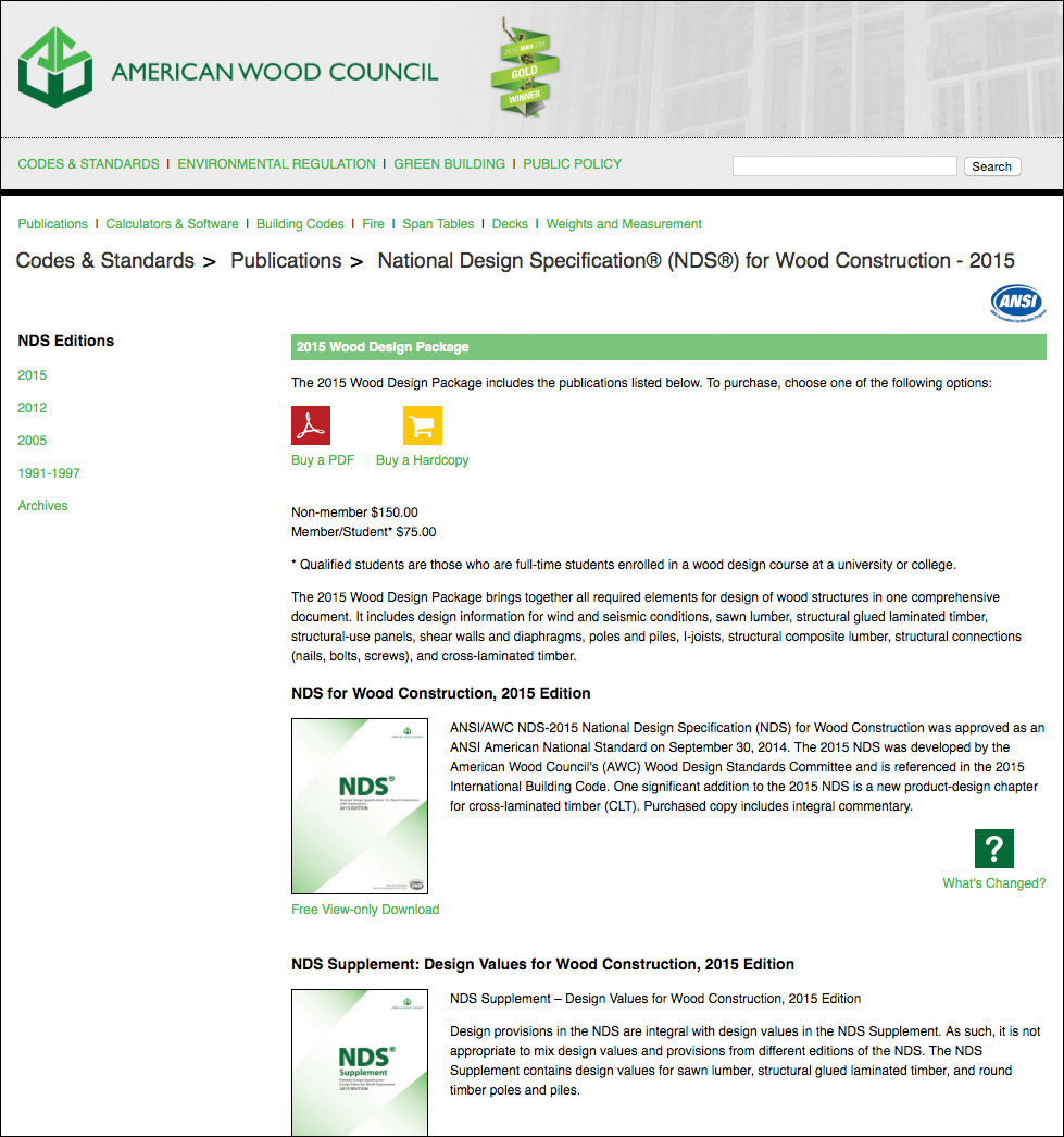
18.3 The American Wood Council publishes the National Design Specification for Wood Construction (NDS). (Courtesy of the American Wood Council.)
Nominal Sizes for Wood Products
The surface of a wood product is finished, or “dressed,” by milling or planing. Owing to wood loss in surfacing, a 1″ thick designation for a thickness is actually ¾″ for dry lumber and 25/32″ for green lumber. Lumber is considered “green” if its moisture content exceeds 19 percent. Table 18.1 shows dressed thickness for various sizes of dry and green wood.
Table 18.1 Nominal and Dressed Sizes for Dry and Green Wood
Nominal Size |
Dressed Thickness, Dry |
Dressed Thickness, Green |
1″ |
3{ {#}}8729;4″ |
25{ {#}}8729;32″ |
2″ to 4″ |
Subtract 1{ {#}}8729;2″ |
Subtract 7{ {#}}8729;16″ |
5″, 6″, and 7″ |
Subtract 1{ {#}}8729;2″ |
Subtract 3{ {#}}8729;8″ |
8″ |
Subtract 3{ {#}}8729;4″ |
Subtract 1{ {#}}8729;2″ |
Symbols for Finished Surfaces on Wood Products
Symbols are used to indicate requirements for finished surfaces on wood.
S2S: Surface two sides.
S2E: Surface two edges.
S4S: All four faces are to have finished surfaces.
The working drawings must show whether standard dressed, standard rough, or special sizes are to be used.
Wood is commonly used for sills, columns, studs, joists, rafters, purlins, trusses, and sheathing in homes and other buildings. Methods of fastening timber members include nails, screws, lag screws, drift bolts, bolts, steel plates, and various special timber connectors.
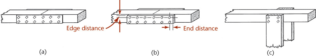
Ordinarily, a structural timber is cut so that the wood fibers, or grain, runs parallel to the length. The strength resistance of wood is not the same in a direction perpendicular to the grain as it is parallel to the grain. Therefore, in designing connections, the direction of the force to be transmitted must be taken into account. Also, proper spacing, edge distance, and end distance must be maintained for screws, bolts, and other connectors.
Wood Joints
Typical bolted joints are shown in Figure 18.4. Either steel or wood splice plates may be used to transmit the forces (Figures 18.4a and 18.4b). A detail without splice plates is shown in Figure 18.4c. Many specialty connectors and shear plates are available.
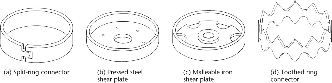
Connector Designs
Each type of connection requires a different design. Figure 18.5 shows split-ring metal connectors. Figure 18.6 shows how split-ring connectors are installed. Figure 18.7 shows a drawing of the left half of a timber roof truss using this type of connector. Only the left half is drawn, because the truss is symmetrical. The views of the top and bottom chords show the relative positions of the connecting members of the structure. In truss drawings, the view of the top chord is an auxiliary view. It is also customary to show the lower chord using a section taken just above the lower chord with the line of sight downward.
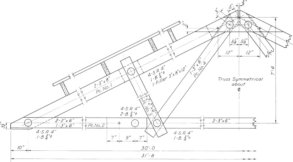
18.7 A Roof Truss (See Exercise 18.1 for the complete drawing.)
Metal Ring Connectors
Metal ring connectors can be installed in wood of proper grade and moisture content to provide increased resistance to shearing loads. The method consists of using either a toothed ring, called an alligator, or a split ring (Figure 18.5a) to connect wood to wood or wood to metal joints.
Toothed Rings
Place the toothed ring (Figure 18.5d) between two members to connect them. Draw the two members together by tightening the bolt so that the teeth of the ring are forced into the two members. The ring assists in transmitting stress from one member to the other.
Split Rings
Cut a groove into each of the two members to connect them. Place the ring in the grooves. Fasten the two members together using a bolt, as shown in Figure 18.6.
The open joint of the ring should be in a direction at right angles to that of the stress, so that as the stress is applied the ring is deformed slightly and transmits the pressure to the wood within the ring as well as to that outside the ring. With this connection, the tensile and shearing strengths of wood are developed to a higher degree than by other methods of connection, and it is possible to use timber in tension much more economically.
It is standard practice to show ring connectors by solid lines, as shown in Figure 18.7.
Straps and Plates
Many specialty straps and plates are available for connecting wood members to wood or other materials (Figure 18.8). Figure 18.9 shows a drawing detail specifying a strap tie holddown. Simpson Strong-Tie Co. is one manufacturer that provides a custom menu for AutoCAD that allows you to easily insert orthographic views of their connectors in your drawings. Use the resources available from manufacturing companies to save time and effort in drawing repetitive detail.
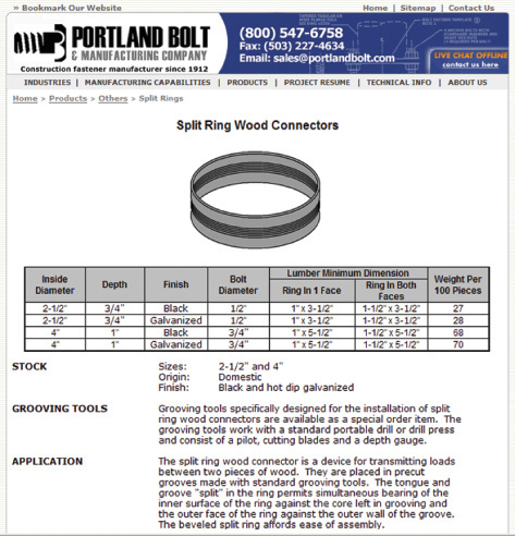
18.8 Design and sizing information is easy to find on the World Wide Web. (Courtesy of Portland Bolt and Manufacturing Company (www.portlandbolt.com).)
Another resource you can find on the Web is the Truss Plate Institute, which provides design and verification services as well as a variety of publications for connecting wood structural members. You can find their resources at www.tpinst.org.
18.2 Structural Steel
Structural steel drawings are ordinarily one of two types: engineering design drawings made by the design engineer, and manufacturing (shop) drawings usually made by the steel fabricator. For a more complete treatment of this subject, consult Detailing for Steel Construction (published by the American Institute of Steel Construction, Chicago, IL).
Design drawings show the overall dimensions of the structure, such as the location of columns, beams, angles, and other structural shapes, and list the sizes of these members. Detail in the form of typical cross sections, special connections required, and various notes are also included.
For example, a building floor plan shows the steel columns in cross section and the beam or girder framing using single heavy lines, as shown in Figure 18.10. Members framing from column to column, providing end support for other beams, are called girders; smaller beams framing between girders are called filler beams. The designer’s plans are sent to the steel fabricator who will furnish the steel for the job. From these plans the fabricator makes the necessary detailed shop drawings and erection plans. Before shop work begins, the fabricator’s drawings are sent to the design engineer for final checking and approval. The design engineer is the authority who makes any changes necessary to ensure the required strength and safety of connections. Once the fabricator receives shop drawings approved by the engineer, the shop work can begin.

Shop drawings consist of detail drawings of all parts of the entire structure, showing exactly how the parts are to be made. These drawings show all dimensions necessary for fabrication, usually calculated to the nearest 1/16″. They also show the location of all holes needed for connections, the details of connection parts, and the required sizes of all material. Notes specify fabrication or construction methods on the detail drawings whenever such items are not covered by separate written specifications. Fabrication, shop methods, and field construction methods must be fully understood by the detailer.
The design of details and connections is an important part of the engineering of the structure. The connections of the various members must be sufficient to transmit the forces in these members. Connection details should be drawn to a scale large enough to show them without crowding. Overall lengths of members are not always drawn to scale in order to show connections clearly. Break lines can be very useful. Show all necessary dimensions. Measurements should never be made from detail drawings by the shop or in the field by the workers making the piece.
Piece Marks
A system is used to mark each piece that is separately handled. This mark is called the piece mark and should be shown wherever the member appears on the drawings (Figure 18.11). The piece mark is also painted on the member in the shop and later serves as a shipping mark and erection mark in the field for final assembly of the member in the structure.
Erection Plans
Erection plans made by the steel fabricator are assembly drawings for the steel structure. They show how the steel parts fit together. The piece marks of the individual members are shown on the erection plan to make it easy to identify individual parts. Show only as much detail as needed so that a skilled worker can assemble the parts. The detail drawings fully describe each member and how it connects, so this information is not needed in the erection plan. Line diagrams show the steel members using heavy straight lines. When the assembly is complex, more detail is needed. Draw the assembly views to scale. As with detail shop drawings, workers should never measure from the drawing to obtain dimensions. Use notes on these drawings to indicate how the structure is to be assembled.
An erection plan for the roof steel framing on a building addition is shown in Figure 18.12. This structure is for a paper roofing products pulp mill. New steel is shown by full lines. Existing roof members are shown by dashed lines. Connections to existing steel members are shown in sectional views. The timber framing for the support of large roof ventilators is also shown.

18.3 Structural Steel Shapes
Structural steel is available in many standard shapes that are formed by the mill by rolling steel billets under high temperatures. (Aluminum and magnesium shapes are also available but are not covered in this text.) Some of the available shapes are square, flat, round bars; plates; equal-leg and unequal-leg angles, American Standard and miscellaneous channels; S, W, M, and HP shapes for beams, columns, and bearing piles; structural tees mill cut from W, S, or M shapes; and standard strong and extra strong pipe and tubing in square, rectangular, or circular cross sections. Figure 18.13 shows some typical cross sections of these shapes and how they are designated or listed in the bill of materials. Use the correct designation on both the design and the detail drawings wherever the structural member appears. For example, designate a wide flange section of 14″ nominal depth, weighing 53 lb per foot and having an overall length of ![]() ″ as
″ as ![]() ″.
″.

Most CAD programs have structural shape symbol libraries available. Templates are also available to save time in drawing structural symbols by hand.
18.4 Specifications
Dimensions, weights, and properties of rolled steel structural shapes, rolling mill practice, and miscellaneous data for designing and estimating is listed in the Manual of Steel Construction (American Institute of Steel Construction, AISC). This is the authoritative manual for structural steel drafting.
Fifteen types or grades of structural steel are available. These differ in chemical composition and physical properties. An ASTM (American Society for Testing Materials) specification defines each type. There are considerable variations in the strengths and costs of the various grades. Economical selection of steel grade depends on physical properties of steels, such as strength, ductility, corrosion resistance, and cost. Specify the type by giving the ASTM designation on the drawing. The most commonly used grade is ASTM A36; the number 36 specifies that the guaranteed minimum yield strength is 36 ksi (36,000 lb/in.2). Many lightweight cold-formed C and Z section shapes are also available.
18.5 Welded and Bolted Connections
The main members of a steel structure are joined together in the field to build the structure. Most joints are welded connections to the main members. Open holes are provided for field bolts that join the members together. Connections are made of angles or connection plates that attach to the main members by riveting or by bolting with either ordinary or high-strength steel bolts in either bearing-type or slip-critical-type connections. High-strength bolts must be field tightened by a specific amount of torque applied to the wrench. Formerly, shop riveting and field riveting were used exclusively in structural work.
Tip: Scales for Detailing
Often, scales of 3/4″ = 1′– 0, or 1″ = 1′– 0 are convenient for showing steel details. The details need to be large enough to show clearly. Owing to the length of steel members, break lines may be necessary. In some cases, scale in any direction may need to be exaggerated to show details.
18.6 Riveted Connections
Although riveting is seldom used now, you may find reference to riveted joints in original plans of structures that require new additions or modifications. Structural rivets are made of soft carbon steel and are available in diameters ranging from 1/2″ to 1-1/4″. Rivets driven in the shop are called shop rivets, and those driven in the field (at the construction site) are called field rivets. Rivets are usually of the button-head type and are driven hot, into holes 1/16″ larger than the rivet diameter. The length of a rivet is the thickness (grip) of the parts being connected, plus the length of the shank necessary to form the driven head and to fill the hole. Excess shank length will produce capped heads, whereas lengths too short will not permit the formation of a full head. Shop rivets are ordinarily driven by large riveting machines that are part of the permanent shop equipment.
Field rivets are heated in a forge at the construction site. The heated rivet is held firmly in the hole with a dolly bar while the pneumatic hammer or rivet gun forms a round, smooth head.
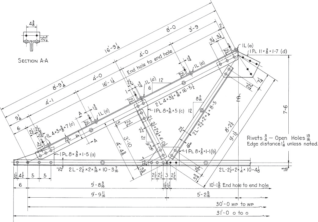
A shop drawing for a riveted roof truss is shown in Figure 18.14. Only the left half is drawn, because the truss is symmetrical about the centerline. Note the use of the gage lines (lines passing through rivets or holes like centerlines) of the members. Locate gage lines close to the centroid of the axes of the members, and at the joints where members intersect. These gage lines should intersect at a single point to avoid unnecessary moment stresses due to off-center locations (eccentricities). The open holes indicate where the field splices are to be—usually at the centerline of the truss (![]() ) for the top chord and at
) for the top chord and at ![]() from the centerline for the bottom chord.
from the centerline for the bottom chord.
18.7 Frame Beam Connections
AISC recommends certain standard connections for attaching beams. These connections are ordinarily adequate to transmit the end forces that beams carry. You should know the strength of these connections and use them only when they are sufficient. For complete information, see the AISC Manual of Steel Construction, Allowable Stress Design (ASD), and Load Resistance Factor Design (LRFD). This manual provides details for standard framed beam connections using 3/4″, 7/8″ and 1″ diameter bolted or riveted connections, and allowable loads for both slip-critical-type and bearing-type connections. The fasteners may have a regular or a staggered arrangement. The holes may be either standard round or oversized slotted ones.
Figure 18.15 shows standard two-angle framed beam connections in a typical detail drawing of a floor beam. This drawing illustrates several important features. Shop rivets are shown as open circles on shop drawings. Holes for field rivets or bolts are blacked in solid. Gage lines are always shown. Line up holes or rivets on these lines when possible rather than “breaking the gage.”
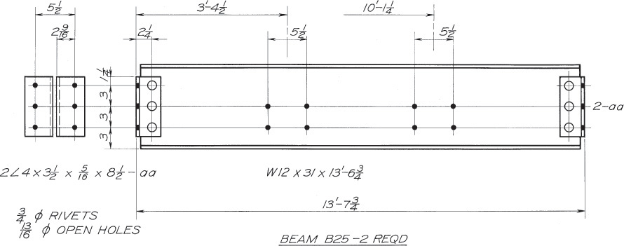
It is necessary to locate the gage line of an angle for each leg, unless it has already been shown for the identical angle elsewhere on the drawing. The edge distance, from end rivet or hole to the end of the angle, must be given at one end; the billed length of the piece is worked out to provide the necessary edge distance at the other end. It is not necessary that the beam extend the full length of the back-to-back distance of end angles. It is shown “set back” at both ends; the length of beam called for is 1″ less than the ![]() distance.
distance.
Below the drawing, the mark B25 is the piece or shipping mark that appears on the erection plan and is to be painted on the member in the shop for identification. The end connection angles are fully detailed at the left end of the beam and are given the assembly mark aa. At the right end where these same angles are again used, only the assembly mark 2–aa, to indicate two angles, is needed. The value ![]() is called an extension figure. This is the distance from the back of the left-end angles to the center of the group of four holes. Note that this dimension is on the same horizontal line as the
is called an extension figure. This is the distance from the back of the left-end angles to the center of the group of four holes. Note that this dimension is on the same horizontal line as the ![]() figure just to the left. It is customary, in giving feet and inches, to give the foot mark (′) after dimensions in feet, but not to give the (″) inch mark, designating inches.
figure just to the left. It is customary, in giving feet and inches, to give the foot mark (′) after dimensions in feet, but not to give the (″) inch mark, designating inches.
18.8 Welding
Welding is a common method for connecting steel members of buildings and bridges. Most steel fabricators have bolt, welding, and riveting equipment available. Some handle only welded fabrication. The fillet weld is most common in structural steel fabrication. Use standard weld symbols to simplify making the shop drawings. For additional information, refer to Chapter 21 and to the relevant specification in the AISC Manual of Steel Construction. When a structure is to be welded, it should be designed throughout for this method of fabrication. It is not economical to merely substitute welding for riveting.
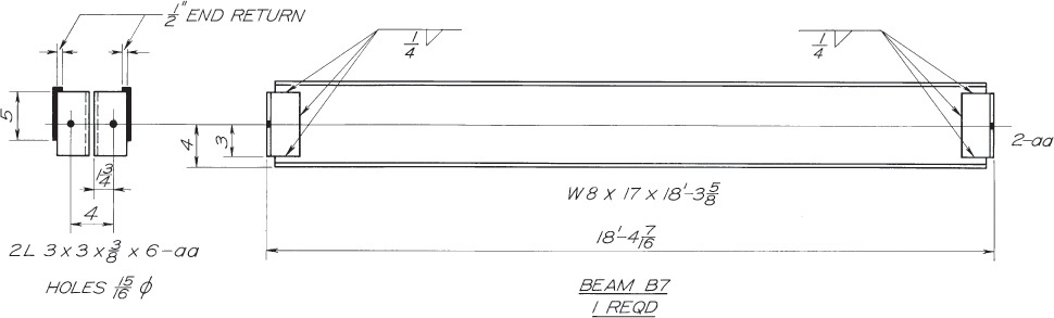
A beam with end connection angles shop welded to the beam web is shown in Figure 18.16. The remaining legs of the angles are to be welded to the connecting columns in the field, as shown in the end view. This view pertains only to field erection. Open holes in the far legs facilitate positioning for the bolts.
A shop drawing of a diagonal bracing between two columns is shown in Figure 18.17. Here the diagonal members are shop welded to gusset plates that are to be bolted to the column flanges as a permanent installation in the field.
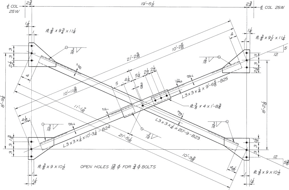
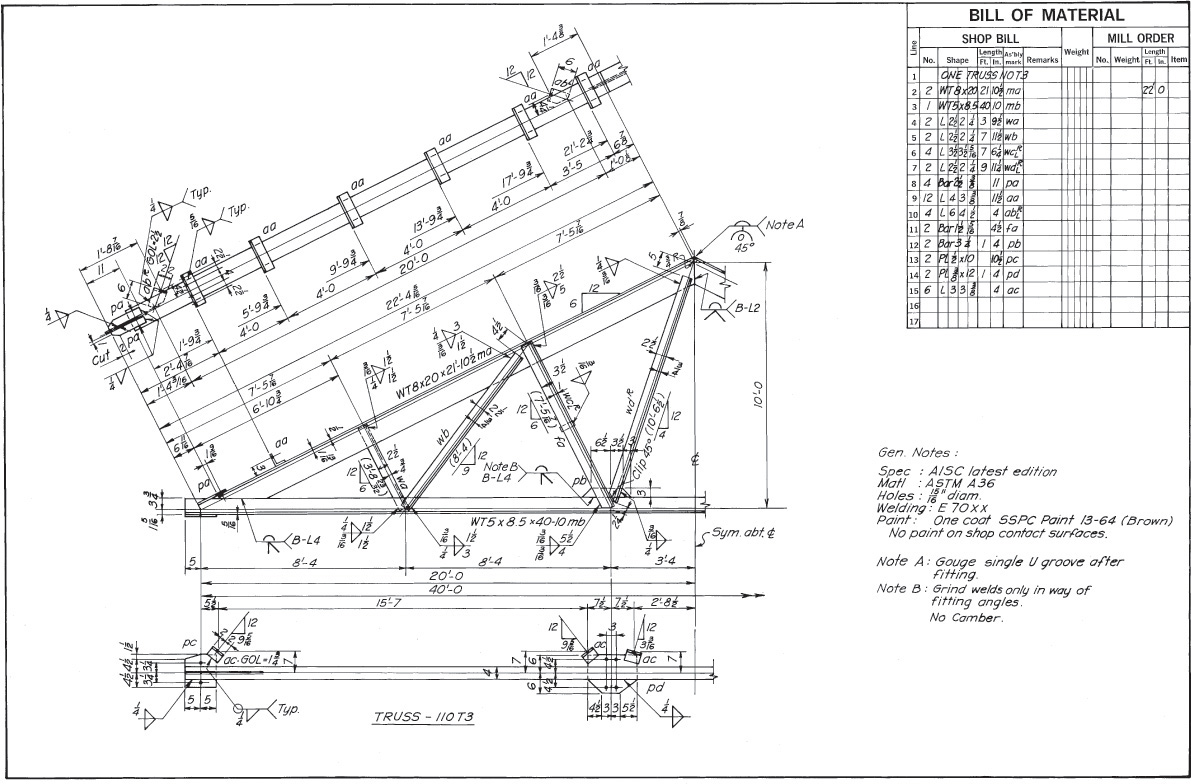
Figure 18.18 is the complete shop drawing for a symmetrical welded roof truss. Because it is symmetrical, only the left half of the structure needs to be shown. Symmetry is shown on the drawing by the note Sym. abt. ![]() . In this drawing,
. In this drawing,
• The clip angles marked aa are to be used for the attachment of roof purlins to the truss.
• The only plate material is the small gusset plate marked pb.
• Most of the connections of web members to chords are made by fillet welding the angles to the webs of the chords.
• The chords are of structural tee (WT) type.
• The top chords are joined at the ridge by butt welding, which is also used at the end of the truss where the chords join.
• Weld symbols and member marks are used.
• Sizes and quantities are listed in the bill of material (BOM).
• The drawing is uncluttered and clear, with lots of important information conveyed under the heading “General Notes.”
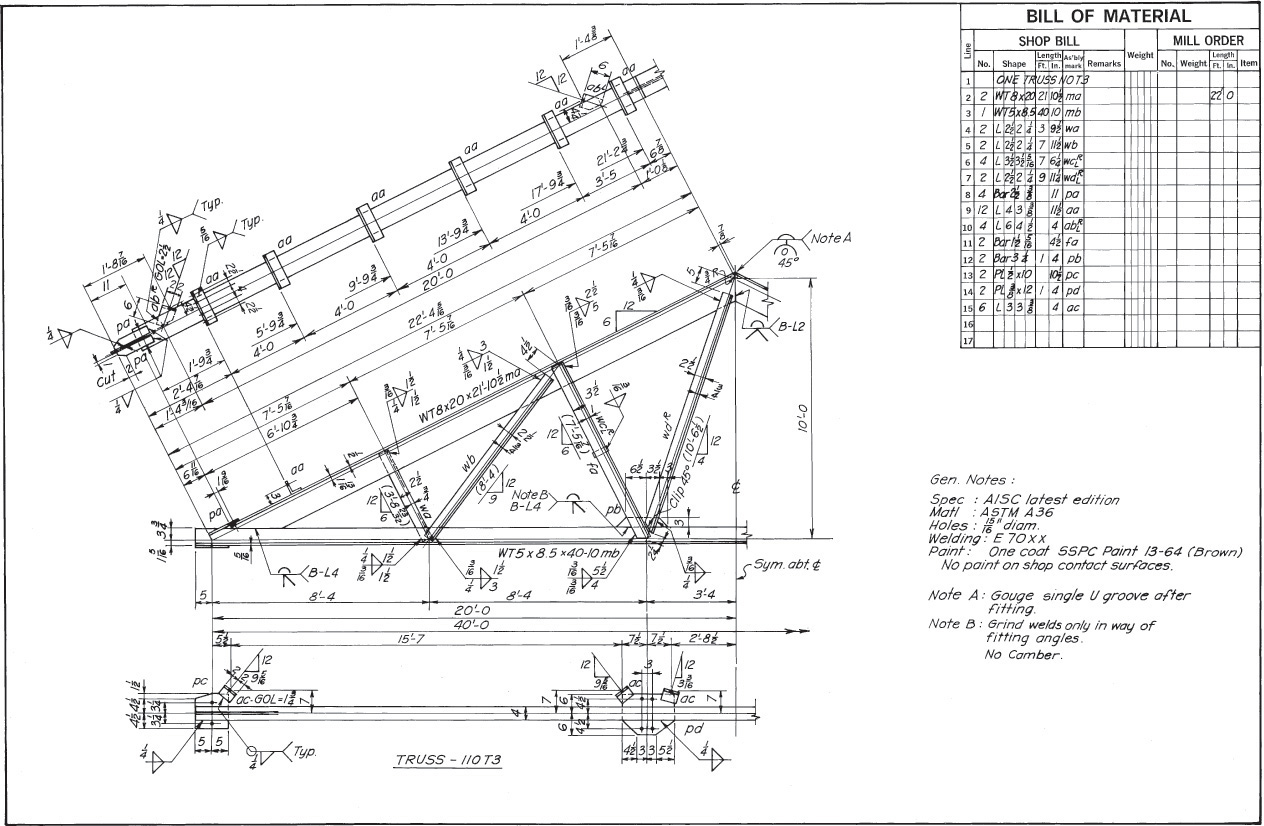
18.18 A Welded Roof Truss (Copyright © American Institute of Steel Construction. Reprinted with permission. All rights reserved.)
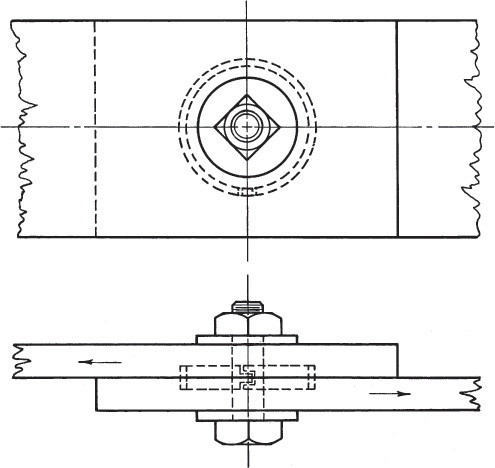
18.9 High-Strength Bolting for Structural Joints
Two common types of high-strength steel bolts are ASTM A325 and A490. The A449 type is physically similar to A325, except that A325 requires the use of special nuts. These bolts are treated by quenching and tempering. A325 bolts are made of medium carbon steel, whereas A490 are made of alloy steel. Metric high-strength structural bolts, nuts, and washers are available. Consult a manufacturer’s catalog or Appendix 17 for specifications. During installation, these bolts are tightened a certain amount, either using the “turn of the nut method” or with a calibrated torque wrench.
Figure 18.19 shows a high strength steel bolt used to transmit a force from the center plate into the two outside plates. When the bolt is fully tightened, the connecting parts are held together by friction, preventing joint slip. This minimizes fatigue failures due to impact or stress reversals. The slip resistance depends not only on the amount of clamping force but also on the nature of the contact surfaces.
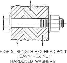
Figure 18.19 shows hardened washers under both head and nut. Whether one or two washers are needed, or none, depends on the method of tightening, the yield stress of the material being joined, and whether the joint is to be the “slip-critical” or “bearing” type.
A bearing-type connection relies on the strength of the bolt shank bearing against the material, and no allowance is made for friction due to clamping action. Specifications for accepted practice, along with installation and inspection procedures, design examples, and reference tables, are covered in High Strength Bolting for Structural Joints (published by Bethlehem Steel Corporation, Bethlehem, PA).
Figure 18.20 shows the complete shop drawing of a steel column of two-floor height. The floors are indicated by reference lines B, 1, and 2 of the drawing. High-strength bolts are used to attach connection material to the W12 × 96 column shaft. The top views at levels 1 and 2 show the outstanding legs of the angles in section plan views. Open holes are shown by the round dots located by dimensions taken from the column centerlines. The open holes are for the insertion of field bolts in beam connections when the entire assembly is erected.
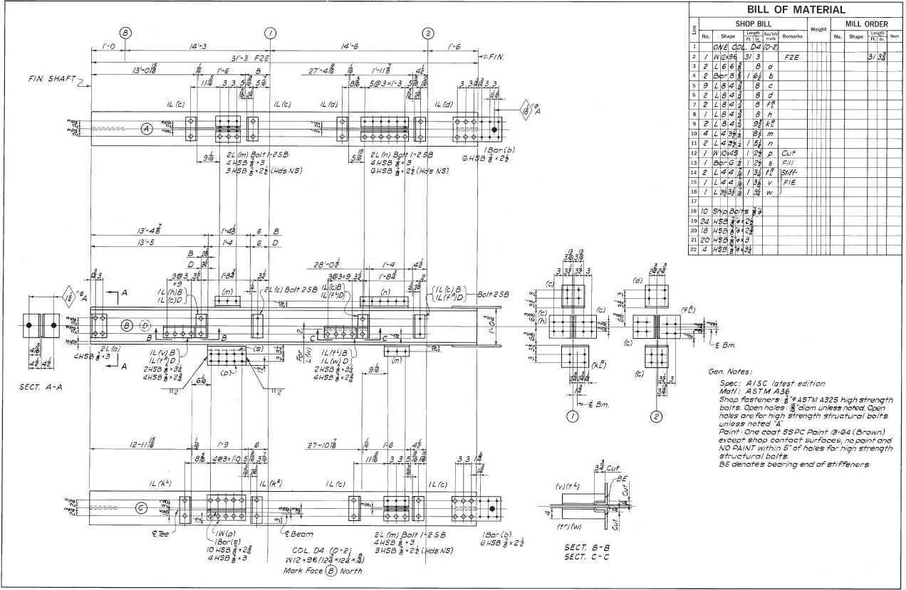
18.20 Steel Column Detail—Bolted Connections (Copyright © American Institute of Steel Construction. Reprinted with permission. All rights reserved.)
Faces A, B, C, and D are designated. Viewing a column from above, designate the faces in counterclockwise order, with faces A and C designating the flanges. For web faces B and D, usually only face B needs to be drawn. However, when the connections on face D are exceptionally complicated, it should be drawn as an additional elevation view.
Note how the drawing shows shop bolts and their designation “HSB” (high-strength bolts).
At the top of this column, splice connection material is provided by Bars (b), for attachment of the shaft above. All material for this column is listed in the bill of material on the drawing.
18.10 Accuracy of Dimensions
An important part of the structural drawing is accurate dimensioning. If there are incorrect dimensions on the drawings, they will result in serious errors and misfits when members are assembled in the field. Correction of such errors not only entails considerable expense but often delays the completion of the work. Because in ordinary steel work dimensions are given to the closest 1/16″, considerable precision is demanded.
Consider the effect of tolerance stacking on the fit of steel members. Review the dimensioning and tolerancing practices in Chapters 11 and 12. Using baseline dimensioning can aid in defining the shape so that tolerances don’t accumulate.
Using CAD, you can accurately list dimensions for the lengths of angled members that would have required trigonometric calculation prior to the advent of CAD.
Do not let the ability of CAD to list accurate dimensions cause you to overlook the fact that real-world fabrication will necessarily have some variation from the exact dimension value.
18.11 Concrete Construction
Concrete is made by mixing sand (fine aggregate) and gravel (coarse aggregate) or other fine and coarse aggregates with Portland cement and water. Its strength varies with the quality and relative quantities of the materials; the manner of mixing, placing, and curing; and the age of the concrete.
The compressive strength of concrete depends on the mix design, but concrete has been manufactured to develop an ultimate strength at 28 days as high as 7,000 psi. The material’s tensile strength is limited to about one tenth its compressive strength. High-strength concrete, used in high-rise construction, has a compressive strength up to 17,000 psi.
Portland cement is a controlled, manufactured product, in contrast to natural cements. Its name is derived from its color, which resembles the color of a famous stone found on the island of Portland in southern England.
Because the tensile strength of plain concrete is very limited, its use as a building material can be improved by embedding steel reinforcing bars so that the steel resists the tension, and the concrete mainly resists the compression. The two materials act together in resisting forces and flexure. Concrete combined with steel in this way is called reinforced concrete.
When the steel is pretensioned before the superimposed load is applied, producing an interior force within the member, the material is called prestressed concrete. The type of steel used in prestressed concrete is flexible but very strong.
18.12 Reinforced Concrete Drawings
The design of the reinforcing material for a reinforced concrete structure and preparation of the corresponding drawings are complicated. To simplify and to secure uniformity throughout engineering offices, the American Concrete Institute (Detroit, MI) publishes a Manual of Standard Practice for Detailing Reinforced Concrete Structures.
The manual recommends the preparation of two sets of drawings: an engineering drawing and a placing drawing. The engineering drawing is prepared by the manufacturer that fabricates the reinforcing steel. It shows the general arrangement of the structure, the sizes and reinforcements of the several members, and such other information as may be necessary for the correct interpretation of the designer’s ideas. The drawing is also used for making forms with precise dimensions before placing the reinforcing bars and casting concrete.
The placing drawing shows the sizes and shapes of the several rods, stirrups, hoops, ties, and so on, and arranges them in tabular forms for reference by the building contractor.
An engineering drawing for a two-way slab and beam floor of a multistory building is shown in Figure 18.21. For examples of placing drawings, consult the American Concrete Institute manual referred to earlier.

Figure 18.22 shows detail views for the reinforced concrete intake for a hydroelectric site. Note that the steel bars, even though embedded in the concrete, are shown by solid lines and that the concrete is stippled in cross section. Unlike shop drawings for structural steel, concrete drawings are ordinarily made to the same scale in both directions. Often a scale of 1/4″ to the foot is adequate, although when the structure is complicated, scales of 3/8″ or 1/2″ to the foot or larger may be used. Note the scale clearly below each detail view. Avoid a cluttered appearance (usually the result of crowding the drawing with notes) by using tables and schedules for listing bar sizes and other necessary data. Cover important points in a single detail drawing or a set of notes.
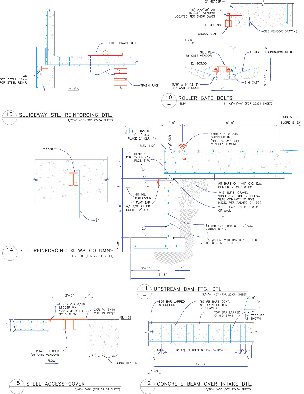
18.22 Reinforced Concrete. Details for the intake for the Power Creek hydroelectric project near Cordova Alaska, which has generation capacity of 30 average annual GWh of renewable energy. (Courtesy of Jason Cohn, Whitewater Engineering Corporation.)
18.13 Structural Clay Products
Brick and tile, which are manufactured clay products, have been in use for centuries and comprise some of the best known forms of building construction. They are made from different types of clay and in many different shapes, forms, and colors (Figure 18.23). Traditionally, they are built into masonry forms by skilled brick or tile masons, who place the units one at a time in a soft mortar. After the mortar hardens, it becomes an integral part of the structure. Typical mortars contain sand, lime, Portland cement, and water. Although the compressive and tensile strengths of the clay units themselves are considerable, the overall strength of the structure is limited by the strength of the mortar joints. The result is a structure of high compressible strength and relatively low tensile strength.
As with concrete, it is possible to reinforce brick and tile masonry by embedding steel rods, thus adding greatly to tension resistance and strength. This material is called reinforced brick (or tile) masonry (RBM).
Information on the manufacture, weight and strength properties, and various uses and applications of structural clay products can be found in the Brick Institute of America handbooks Principles of Brick Engineering and Principles of Tile Engineering.
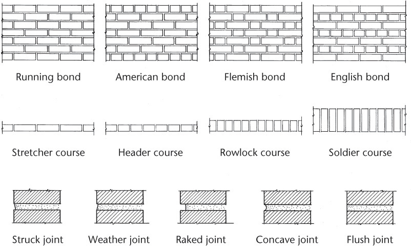
Bricks are made in various sizes, with the ![]() ″ building brick being most common. Thickness of mortar joints usually varies from 1/4″ to 3/4″, with 3/8″ and 1/2″ most common. Of the several methods of bonding brick (Figure 18.23), the following are the most common:
″ building brick being most common. Thickness of mortar joints usually varies from 1/4″ to 3/4″, with 3/8″ and 1/2″ most common. Of the several methods of bonding brick (Figure 18.23), the following are the most common:
In running bond, all face brick are stretchers and are generally bonded to the backing by metal ties.
In American bond, the face brick are laid alternately, five courses of stretchers and one course of headers.
In Flemish bond, the face brick are laid with alternating stretchers and headers in every course.
In English bond, the face brick are laid alternately, one course of stretchers and one course of headers.
These standard methods of bonding are frequently modified to produce various artistic effects. Typical brick lintel arches are shown in Figure 18.24.

In addition to its use as a basic building material, tile is used in fireproofing structural steel members. Most building codes require that the steel members be enclosed in concrete or masonry so that fire will not cause collapse of the structure. Hollow tile units, which are light and relatively inexpensive, are well adapted to this use.
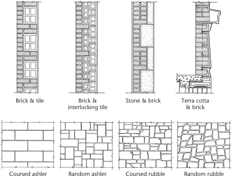
18.14 Stone Construction
Natural stone—generally limestone, marble, sandstone, or granite—is used in masonry construction, most commonly for ornamental facing.
Ashlar masonry (also spelled ashler) is formed of stones cut accurately to rectangular faces and laid in regular courses or at random with thin mortar joints.
Rubble masonry is formed of stones of irregular shapes laid in courses or at random with mortar joints of varying thickness.
Manufactured stone is concrete made of fine aggregate for the facing and coarse aggregate for the backing. The fine aggregate consists of screenings of limestone, marble, sandstone, or granite, to present an appearance similar to natural stone. Manufactured stone is made of any desired shape, with or without architectural ornament.
Architectural terra cotta is a hard-burned clay product and is used primarily for architectural decoration and for wall facing and wall coping.
Brick, stone, tile, and terra cotta are combined in many different ways in masonry construction. A few examples are shown in Figure 18.25.
CAD at Work: CAD Tools for Structural Drawings
Structural drawings use a variety of standard symbols and methods of representation. A number of CAD symbol libraries are available that allow users to quickly generate drawings of structural steel shapes, connecting members, and steel erection plans. Once plans have been created, other programs are available to automatically calculate areas and perform finite-element analysis on the design.
3D constraint-based software platforms often provide very sophisticated steel shapes that can be inserted to create assemblies that are easy to modify.
SDS/2 software from Design Data lets you designate the material edge distance, cope criteria, and other connection parameters to create 3D models of a structure. The software’s automatic detailing feature makes it simple to produce 2D detail drawings, so the information can be communicated to the crew erecting the structure.
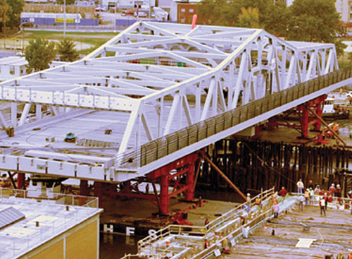
Construction of the 3rd Avenue Bridge over the Bronx River (Courtesy of Design Data and GeniFab, Inc.)
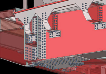
Detail of a Bolted Connection for the Bridge Structure (Courtesy of Design Data and GeniFab, Inc.)
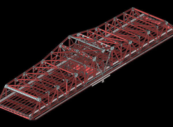
3D Model of the Bridge Structure Created in SDS/2 Software (Courtesy of Design Data and GeniFab, Inc.)
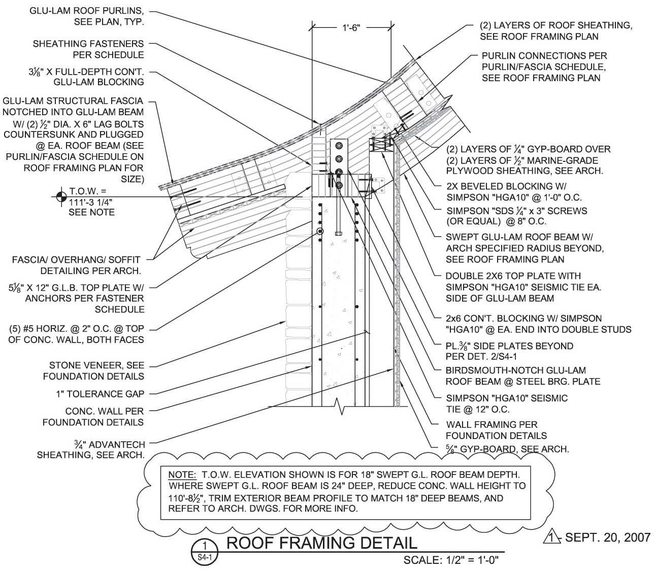
Construction Detail for Attaching a Glu-Lam Beam to a Concrete Wall (Courtesy of Hicks Engineering PC.)

Chapter Summary
• The structural drawing is one of the most important elements in construction drawings.
• Cost and safety are important considerations when designing a structure that people will use, such as a building or bridge.
• Structural drawings are precise, detailed instructions for general contractors, who must create the structure according to the information in the drawings.
• Steel is commonly used in commercial construction because of its strength and durability. Steel shape and size designations are different from those for other materials, such as wood.
• Structural drawings show both plan and elevation views.
• Details about how structural members are connected and fastened to each other are critical parts of a structural drawing.
• Structural drawings use more notes about size, shape, location, and fastening details than other types of drawings.
• Safety is dependent on correctly following the engineer’s design. Careful proofing and checking of every note and detail is an essential part of the engineering process.
• The list of materials, including their size, shape, and detail information, is often included in a material schedule that appears in table form in a corner of the drawing.
• When components are welded together, standard welding symbols and notes must be used.
Review Questions
1. List five structural materials.
2. Draw four different structural steel shapes and label each shape.
3. How is reinforced concrete different from regular concrete?
4. What is shown in the plan view of a structural drawing?
5. What is shown in the elevation view of a structural drawing?
6. Would the spacing for steel roof trusses be shown in a plan view or an elevation view?
7. Would the individual members of a roof truss be shown in a plan view or an elevation view?
8. What are the most common fastening techniques for joining structural steel?
Chapter Exercises
The following problems are intended to offer practice in drawing and dimensioning simple structures and in illustrating methods of construction. They may be completed by hand or using CAD.
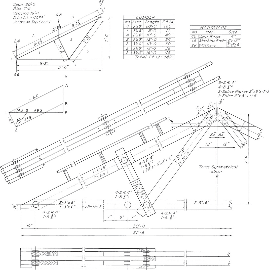
Exercise 18.1 Calculate point-to-point lengths (the distances between centers of joints) of the web members of the roof truss based on a design by Timber Engineering Company. Make a detailed drawing of web member piece No. 4.
Exercise 18.2 Make a complete detail of the top chord member of the truss shown for a 30° angle of inclination.
Exercise 18.3 Assuming riveted construction, with rivets of 3/4″ or 20 mm diameter, make a complete shop drawing for a typical filler beam of the steel floor design plan shown. Detail the same beam for welded construction. Consult the AISC Manual of Steel Construction.
Exercise 18.4 Assuming the column size to be W8 × 31, detail the W16 × 36 girder at the center of the drawing.
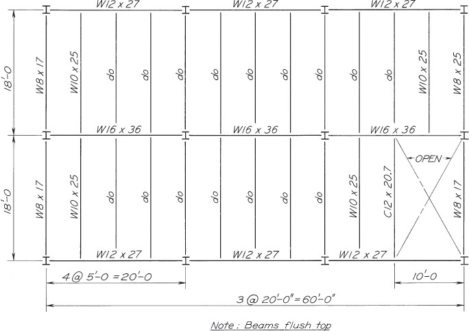
Typical Steel Floor Design Plan
A Welded Roof Truss (Copyright © American Institute of Steel Construction. Reprinted with permission.)
Exercise 18.5 Make a complete detail for a truss of the same length, but change the height from 10′-0 to 6′-8. Use angle members of the same cross section sizes as those shown, but of different lengths, as needed.

Exercise 18.6 Make a similar bracing detail as for the detail drawing of the column bracing shown, also changing the distance between column centers from 20′-0 to 18′-6.

Exercise 18.7 Draw cross sections through panel D in both directions for the engineering drawing for a two-way slab and beam floor shown. Include the supporting beams in each cross section, and show all dimensions, size and spacing of reinforcing steel, and dimensions to locate the ends of bars and the points of bend for the bent bars. Also show and locate the stirrups in these views.
Exercise 18.8 Detail the brickwork surrounding a window frame for an opening 4′-7/8″ wide by 6′-9″ high. Use the type of curved arch lintel as shown. Assume standard-size building brick with mortar joints.
Exercise 18.9 Consult Principles of Tile Engineering and draw a cross-sectional view through a 12″ wall of composite brick and tile construction.
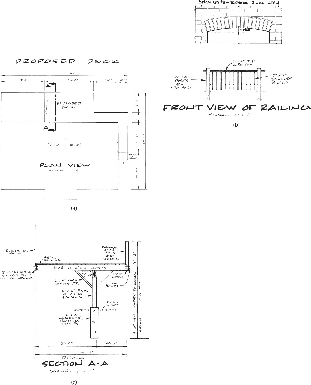
Exercise 18.10 Referring to the figure, redraw a complete detail of this proposed deck, changing the total width of the deck from 12′ to 14′ and the length from 52′ to 54′.
Exercise 18.11 Referring to part b of the figure, adjust the dimensions on the posts from 4″ × 4″ to 6″ × 6″. Redraw a complete detail of the railing view and Section A–A.

Exercise 18.12 Referring to part a of the figure, adjust the post dimensions from 4″ × 4″ to 6″ × 6″. Redraw a complete detail of part a.
Exercise 18.13 Referring to part c of the figure, insert the adjustments made to the post detail in Exercise 18.12 and redraw the complete foundation plan.