
Chapter Twenty. Piping Drawings
Objectives
After studying the material in this chapter, you should be able to:
1. Identify cast iron, brass, copper, and thermoplastic pipe and tubing fittings.
2. Draw and label common pipe joints using ANSI/ASME standard designations.
3. Draw the multiview or pictorial piping drawings using standard schematic symbols.
4. Draw the schematic symbols for valves and identify flow direction.
Refer to the following standards:
• ASME Y32.2.3 Graphic Symbols for Pipe Fittings, Valves, and Piping (Removed February 11, 2003. Historical reference only.)
• AWWA C110/A21.10-03 Ductile-Iron and Grey-Iron Fittings for Water
• ISA 5.1 Instrumentation Symbols and Identification
A Complex Arrangement of Pipes and Tubes at a Gas Processing Plant (Copyright Christian Lagerek/Shutterstock.)
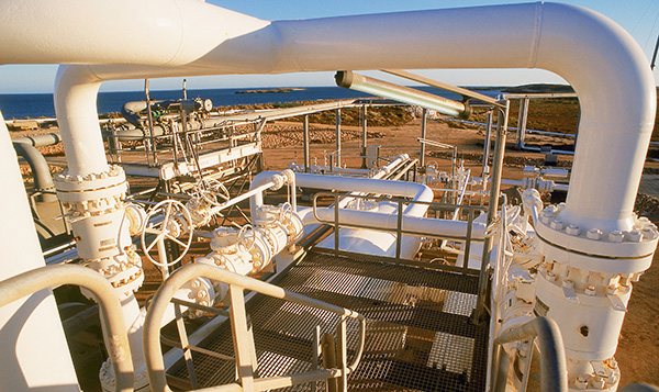
Piping valves and joints such as those shown in this photo are typically shown using schematic symbols in technical drawings. (Courtesy of GILLIANNE TEDDER/Photolibrary.com)
Understanding Piping Drawings
Standard Symbols
To make drawings of piping systems quick to produce and easy to read, a standard set of symbols shown in Appendix 33 has been developed to represent the various pipe fittings and valves. Figure 20.1 shows a few of the standard symbols. CAD systems have standard symbols available, and templates for drawing piping symbols are a time-saver when you are sketching piping.
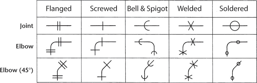
20.1 Standard Piping Symbols (See Appendix 33)
Types of Drawings
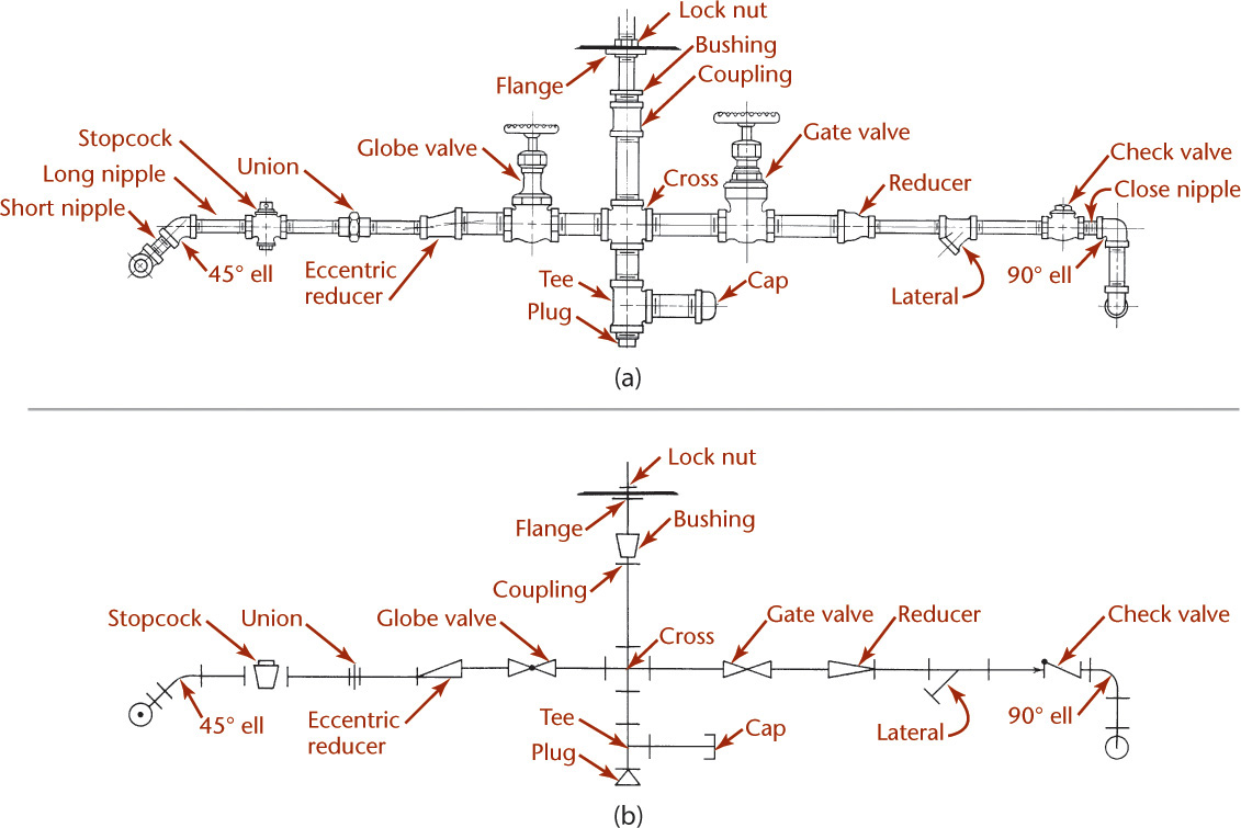
Two types of drawings are common for piping systems: single- and double-line.
Single-line drawings show the centerline of the pipe as shown in Figure 20.2b.
Double-line drawings show two lines representing the pipe diameter as shown in Figure 20.2a and Figure 20.8.

Either type of drawing can be used in orthographic drawings, orthographic section views, or pictorial drawings. An example of an orthographic drawing of a piping system is shown in Figure 20.7. In complicated systems, where a large amount of piping of various sizes is run in close proximity and where clearances are important, the use of double-line multiview drawings, made accurately to scale, is desirable.
Axonometric projections are also used for piping drawings. Figure 20.4 shows an oblique projection used for a piping diagram. The drawing shown in Figure 20.5 is a modified form of oblique projection generally used in representing the piping arrangement for heating systems. In these cases, the pipe mains are shown in plan and the risers in oblique projection in various directions to make the representation as clear as possible.
In most installations, some pipes are vertical and some are horizontal. If the vertical pipes are revolved into the horizontal plane or if the horizontal pipes are revolved into the vertical plane by turning some of the fittings, the entire installation can be shown in one plane, as shown in Figure 20.6c. This is called a developed piping drawing.

Showing the relative positions of component parts in all views reduces the probability of interference when the piping is erected and is almost a necessity when piping components are prefabricated in a shop and sent to the job in finished dimensions. Prefabrication is common for large systems and large pipe sizes. Most piping 2-1/2″ and larger is shop fabricated.
3D CAD is useful for creating piping drawings. Showing the centerline of the pipe along with the valve may often be all that is necessary. Extrude the pipe diameter along the centerline to produce a drawing that shows the entire pipe when more detail is needed. Automated interference checking, available in 3D CAD, can help eliminate errors in the design.
Dimensioning Piping Drawings
In dimensioning a piping drawing, give distances from center to center (c to c), center to end (c to e), or end to end (e to e) of fittings or valves and the lengths of all straight runs of pipe, as shown in Figure 20.7. Fully dimensioned single-line drawings are not always drawn to scale. You may find it useful to use break lines and omit portions of the straight pipe.
Allowances in pipe lengths for makeup in fittings and valves must be made in preparing a bill of materials.
Show the centerlines in double-line drawings if they are to be dimensioned.
Show the size of the pipe for each run by a numeral or by a note at the side of the pipe. Use a leader when necessary for clarity.
20.1 Steel and Wrought Iron Pipe
Steel or wrought iron pipe is used for water, steam, oil, and gas. Until the early 1930s, it was available in only three weights, known as “standard,” “extra strong,” and “double extra strong.” At that time increasing pressures and temperatures, particularly for steam service, made the availability of more diversified wall thicknesses desirable.
The American National Standards Institute/American Society of Mechanical Engineers (ANSI/ASME) has developed dimensions for 10 different schedules of pipe (see Appendix 42). The table in Appendix 42 shows dimensions for nominal sizes from 1/8″ to 24″. Dimensions have not been established for all schedules. In the different schedules, the outside diameters (O.D.) are maintained for each nominal size to facilitate threading and the uniform use of fittings and valves.
Certain of the schedule dimensions correspond to the dimensions of “standard” and “extra strong” pipe. These are shown in boldface type in the appendix. The schedule dimensions shown for Schedules 30 and 40 correspond to standard pipe, and those for Schedule 80 correspond to extra strong pipe. There are no schedule dimensions corresponding to double extra strong pipe. Some of the established schedule dimensions may not always be commercially available, so investigate before specifying pipe on drawings. Generally, schedules 40, 80, and 160 are readily available.
Note that the actual outside diameter of pipe in nominal sizes 1/8″ to 12″ inclusive is larger than the nominal size, whereas the outside diameter of pipe in nominal sizes 14″ and larger corresponds to the nominal size. Pipe in nominal sizes 14″ and larger is commonly referred to as O.D. pipe.
Pipe may be welded or seamless. Welded pipe is available in schedules 40 and 80 in the smaller sizes. Lap welded pipe is made in sizes up to and including 2″. Butt welded pipe is available as furnace-welded material, in which a formed length is heated in a furnace and then welded, in sizes up to and including 3″. Butt welded pipe is also available as continuous welded pipe, in which the finished pipe is continuously heated, formed, and welded from a roll of strip steel, in sizes up to and including 4″. Seamless pipe is made in both small and large sizes.
Many applications require the use of alloys to withstand pressure–temperature conditions without having to be excessively thick. Many alloys are available in both ferritic and austenitic material. Refer to the specifications of the American Society for Testing Materials (ASTM) for these alloys and for dimensional tolerances.
Steel pipe is available as black pipe or as galvanized pipe. Galvanized pipe is used for water distribution, and black pipe for natural gas.
Steel or wrought iron pipe comes in lengths up to about 40′ in the small sizes, with the length decreasing with increasing size and wall thickness.
20.2 Cast Iron Pipe
Cast iron (C.I.) pipe is used for water or gas service and as soil pipe. For water and gas pipe, it is generally available in sizes from 3″ to 60″ inclusive and in standard lengths of 12′. Various wall thicknesses satisfy different internal pressure requirements. The dimensions and the pressure ratings of the various classes are shown in Appendix 43.
Generally, water and gas pipes are connected with bell and spigot joints (Figure 20.9a) or flanged joints (Figure 20.9b), although other types of joints are also used (Figure 20.9c).
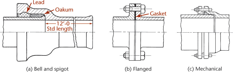
As soil pipe, cast iron pipe is available in sizes 2″ to 15″ inclusive, in standard lengths of 5′, and in service and extra heavy weights. Soil pipe is generally connected with bell and spigot joints, but soil pipe with threaded ends is available in sizes up to 12″.
Using cast iron pipe, designers consider both the internal pressure and the external loading, due to fill and other loadings, such as roads and tracks. Cast iron pipe is brittle, and settling can cause fracture unless the joints are sufficiently flexible. This is why flange joints are not usually used for buried pipes unless they are adequately supported.
20.3 Seamless Brass and Copper Pipe
Pipe made of brass and copper is available in approximately the same dimensions as “standard” and “extra strong” steel pipe. It is used in plumbing for supply, soil, waste drain, and vent lines. It is also particularly suitable for process work where formation of scale or oxidation in steel pipe would be troublesome. Brass pipe and copper pipe are available in straight lengths up to 12′.
Brass pipe, generally known as red brass pipe, is an alloy of approximately 85% copper and 15% zinc. Copper pipe is practically pure copper with less than 0.1% of alloying elements.
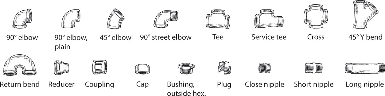
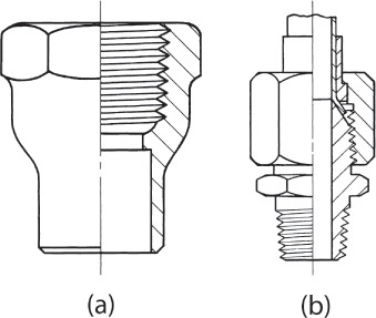
Brass pipe and copper pipe should be joined with fittings of copper-base alloy to avoid galvanic action resulting in corrosion. Where screwed joints are used, fittings similar to cast or malleable iron fittings are available (Figure 20.10).
Flanged fittings of brass and copper are of different dimensions than fittings made of ferrous material. Refer to dimensional standards published by the American National Standards Institute (ANSI/ASME B16.24) for dimensions of brass and copper fittings.
20.4 Copper Tubing
Copper tubing is often used in applications for nonferrous construction in sizes below 2″. It is suitable for process work, for plumbing, and for heating systems (particularly radiant heating).
Copper tubing is made as hard temper and as soft tubing. Hard temper tubing is much stiffer than soft tubing and is used when rigidity is desired. Soft tubing is easy to bend and is used where bending during assembly is required. Neither hard nor soft temper tubing has the rigidity of iron or steel pipe and must be supported at frequent intervals. Where multiple runs of parallel tubes are used over distances of 20′ or more, parallel runs of soft tubing are laid in a trough to provide continuous support.
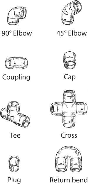
Copper tubing joints are usually made with flared joints (Figure 20.11a), or solder joints (Figure 20.11b). There are several types of flared joints, but the basic design of making a metal-to-metal joint is common to all. Fittings, such as tees, elbows, and couplings, are available for flared joints.
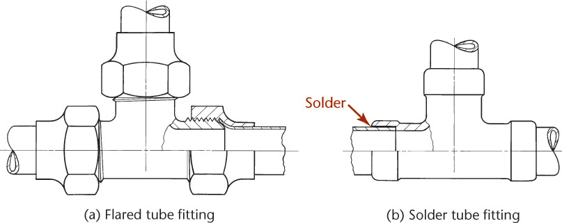
Solder joints are also known as capillary joints because the annular space between the tube and the fitting is so small that the molten solder is drawn into the space by capillary action. The solder may be introduced through a hole in the fitting (Figure 20.12) or through the outer end of the annular space. Fittings can be purchased with a factory-assembled ring of solder in the fitting. Solder joints may be made with soft solder (usually 50/50 or 60/40 tin and lead) or with silver solder. Silver solder has a higher melting point than soft solder, makes a stronger joint, and is suitable for higher operating temperatures.
Copper pipe or tubing has an upper operating temperature limit of 406 °F. If solder fittings are used, the upper temperature limit depends on the softening point of the solder rather than the temperature limit of the base material.
Copper tubing can be connected to threaded pipe or fittings using adapters. Adapters are available with either male or female pipe threads and with either flared or solder connections for the tubing. Two types are shown in Figure 20.13.
Copper tubing is available in straight lengths up to 20′ or in coils of 60′ for soft temper material. Hard temper material is available in straight lengths only, because it cannot be coiled. Installation costs for coiled material are lower, because fewer joints are needed. Copper tubing is available in both O.D. and nominal sizes.
20.5 Plastic and Specialty Pipes
Pipe and tubing of other material, such as aluminum and stainless steel, are also available. A wide variety of plastic pipe, both rigid and flexible, is used in construction. Plastic pipe is lightweight, corrosion proof, resistant to many chemicals, and has a smooth inner surface which offers low flow resistance.
PVC (polyvinyl chloride) pipe and fittings are available in Schedule 40 and extra heavy Schedule 80. Schedule 80 is used where higher working pressures are present and may be threaded. Schedule 40 should not be threaded, and is normally assembled with slip fittings and solvent. The maximum temperature rating for PVC is 140 °F (110 °C).
CPVC (chlorinated polyvinyl chloride) pipe is similar to PVC and has a higher maximum temperature rating, 180 °F (132 °C). Both PVC and CPVC pipe are commonly available in sizes ranging from 1/2″ to 4″ inside diameter (I.D.).
Black polyethylene flexible pipe, approved by the National Sanitation Foundation for use with drinking water, has a rated working pressure of 100 psi when not exposed to direct sunlight. It is available in sizes from 1/2″ to 2″ I.D. Black polyethylene pipe should not be used on hot-water lines or exposed to temperatures greater than 100 °F (88 °C). It is often used for underground lawn sprinkler systems.
HDPE (high-density polyethylene) is available in sizes from 1/2″ to 63″ in a variety of wall thicknesses and shapes.
The applications of these materials vary according to their physical properties and temperature–pressure limitations. Regardless of the material used in a piping system, the procedure followed in the design of the system and the creation of the necessary drawings remains basically the same.
20.6 Pipe Fittings
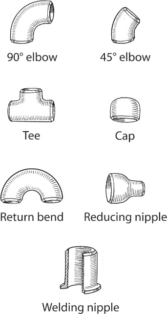
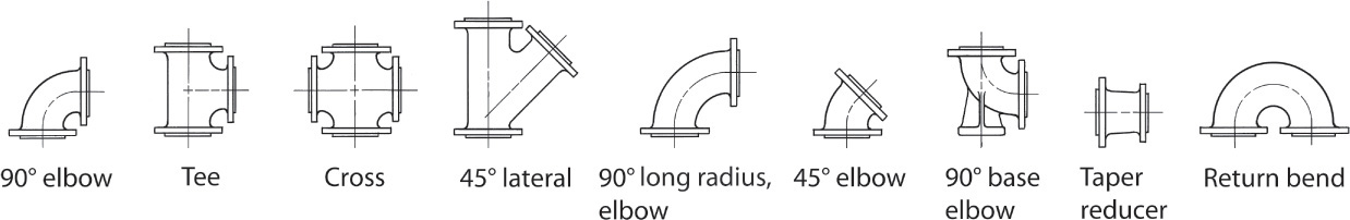
Pipe fittings are used to join lengths of pipe, to provide changes of direction, to provide branch connections at different angles, or to effect a change in size. They are made of cast iron, malleable iron, cast or forged steel, nonferrous alloys, and other materials for special applications. Pipe fittings are available in different weights and should be matched to the pipe they are used with. Ferrous fittings are made for threaded, welded, or flanged joints. Nonferrous fittings are made for threaded, solder, flared, or flanged joints. The common types of fittings for threaded joints were shown in Figure 20.10. Common fittings for solder joints were shown in Figure 20.12. Fittings for welded joints are shown in Figure 20.14, and for flanged joints in Figure 20.15.
Where both or all ends of a fitting are the same nominal size, the fitting is designated by the nominal size and the description—for example, a 2″ screwed tee. Where two or more ends of a fitting are not the same nominal size, the fitting is designated as a reducing fitting, the dimensions of the run precede those of the branches, and the dimension of the larger opening precedes that of the smaller opening—for example, a 2″ × 1-1/2″ × 1″ screwed reducing tee. See Figure 20.16 for typical designations.

The threads of screwed fittings conform to the pipe thread with which they are to be used, either male or female.
Dimensions of 125 lb cast iron screwed fittings, 250 lb cast iron screwed fittings, 125 lb cast iron flanged fittings, and 250 lb cast iron flanged fittings are shown in Appendices 46–47 and 49–50.
20.7 Pipe Joints
The joints between pipes, fittings, and valves may be screwed, flanged, welded, or, for nonferrous metallic materials, soldered. Plastic pipes may be screwed together or fastened with slip joints and solvent or with compression fittings.
The American National Standard pipe threads were illustrated in Figures 13.27–13.29, and tabular dimensions are shown in Appendix 42. The threads of the American Petroleum Institute (API) differ somewhat from the American National Standard pipe threads. Refer to the API Standards for these differences.
Threaded joints can be made up tightly by simply screwing the cleaned threads together. However, it is common practice to use pipe compound, as it lubricates the threads and enables them to be screwed together more tightly. It also serves to seal irregularities, providing a tighter joint. Pipe compound is applied to the male thread only, to avoid forcing it into the pipe and to prevent contamination or obstruction.
Flanged Joints
Flanged joints are made by bolting two flanges together with a resilient gasket between the flange faces. Flanges may be attached using a screwed joint or by welding, lapping the pipe, or being cast integrally with the pipe, fitting, or appliance.
The faces of the flanges between which the gasket is placed have different standard facings, such as flat face, 1/16″ raised face, 1/4″ raised face, male and female, tongue and groove, and ring joints. Flat face and 1/16″ raised face are standard for cast iron flanges in the 125 lb and 250 lb classes, respectively. The other types of facing are standard for steel flanges.
The number and size of the bolts joining these flanges vary with the size and the working pressure of the joint. Bolting for Class 125 cast iron and Class 250 cast iron flanges are shown in Appendices 46 and 49, respectively.
For dimensions of the various flange facings and for flange and bolting dimensions of the various sizes and pressure standards of steel flanges, refer to the American National Standard for Steel Pipe Flanges and Flanged Fittings (ANSI/ASME B16.5), which is too extensive to be included here. Some special types of flanged joints are shown in Figure 20.17.

Welded Joints
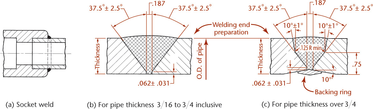
Piping construction using welding joints is in almost universal use today, particularly for higher pressure and temperature conditions. Such joints may either be socket welded or butt welded (Figure 20.18). Socket welded joints are limited to use in small sizes. The contours of the butt welded joints shown in Figure 20.18a and c are those shown in ANSI/ASME B16.25.
20.8 Valves
Valves are used to stop or regulate the flow of fluids in a pipeline. The more common types are gate valves, globe valves, and check valves. Other types, such as pressure-reducing valves and safety valves, are used to maintain a desired lower pressure on the downstream side of the valve or to prevent undesirable overpressure, respectively.
Globe Valves
Globe valves have approximately spherical bodies with the seating surface at either a right or an acute angle to the centerline of the pipe (Figure 20.19a). In a globe valve, the flowing fluid makes abrupt turns in the body resulting in higher pressure loss than in a gate valve.

Globe valves are commonly used for close regulation of flow and are less subject to cutting action in throttling service than gate valves.
Inside screw and outside screw and yoke (OS & Y) type valves are also available. Angle valves and needle valves are special designs of the general class of globe valves.
Check Valves
Check valves are used to limit fluid flow to only one direction. Swing check valves use a disk that may be hinged to swing partially out of the stream (Figure 20.19b). Lift check values use a disk that is guided so that it rises vertically from its seat.
Gate Valves
Gate valves have full-size straightway openings that offer small resistance to the flow of fluid. The gate, or disk, may rise on the stem (inside screw type) (Figure 20.19c), or the gate may rise with the stem, which in turn rises out of the body (rising stem, or outside screw and yoke type). Inside screw type valves are used in the smaller sizes and lower pressures.
Seating may be on nonparallel seats, in which case the disk is solid and wedge shaped. There is also a type of gate valve that uses parallel seats. In this type, two disks are hung loosely on the stem and are free of the seats until an adjusting wedge reaches a lug at the closed position of the valve, when further movement of the stem causes the wedge to spread the disks and form a tight joint on the parallel seats. These valves are used only on low-pressure and low-temperature services.
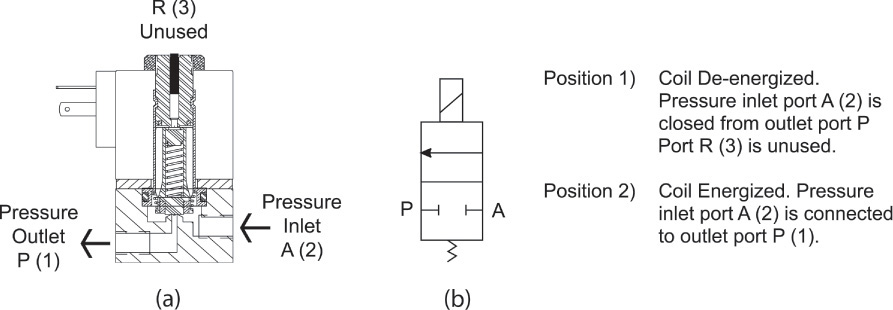
Solenoid-Actuated Valves
A thermostatically controlled heating system is an example of process control. When you set your home thermostat to a particular value, the heating system is typically controlled using solenoid actuated valves to try to meet the set temperature value. Solenoid valves are electromechanical devices often used to regulate the flow of liquid or gas. Drawings for process control often combine electronic and piping elements to show how the process is controlled. Figure 20.20a shows a cross-sectional view of a two-way, two-position, normally closed solenoid valve. Figure 20.20b shows a schematic diagram for a two-way, two-position, normally closed solenoid flow control valve.
20.9 American National Standard Code for Pressure Piping
The American National Standards Institute has adopted an American National Standard Code for Pressure Piping (ANSI/ASME B31.1). This compilation of recommended practices and minimum safety standards covers various types of piping, such as power piping, industrial gas and air piping, oil refinery piping, oil transportation piping, refrigerating piping, chemical industry process piping, and gas transmission and distribution piping.
CAD at Work: Piping Drawing for a Field Instrument
MSE Technology Applications, Inc. (MSE) designed a field instrument to expedite the process of sorting drums containing volatile organic compounds (VOCs). The previous sorting process used a gas chromatograph/mass spectrometer (GC/MS) which was time consuming and relatively expensive. Drums were required to pass two independent field measurements before they could be transported. Figure A is a schematic diagram showing the valves, filters, piping and other features for the instrumentation.
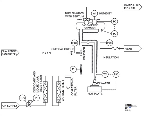
From each drum a headspace gas sample was drawn and analyzed first by a field-ready flame ionization detector (FID) VOC meter. A second field instrument, a photo ionization detector (PID) VOC meter equipped with a 10.6-eV lamp analyzed the headspace gas a second time. If the sum of the two VOC measurements were less than 500 ppmv, the waste was designated less than 500 ppmv flammable VOCs and therefore allowed to be shipped. Tests of the device showed the portable field instruments provided a confident approach to sampling and analyzing headspace gas in drums, saving time and avoiding the costly GC/MS analysis previously used.
The actual equipment, when assembled, looked very similar to the 3D CAD model shown in Figure B.
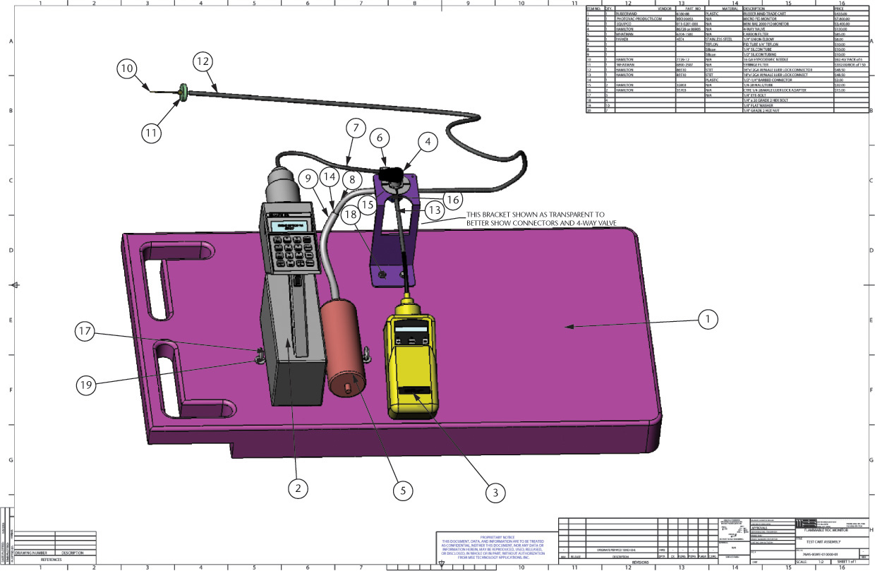
(B) Assembly Drawing and Parts List from the 3D CAD Model (Courtesy of MSE Technology Applications, Inc.)

Double-Line Piping Plan and Elevation Drawing (Courtesy of CH2M Hill.)
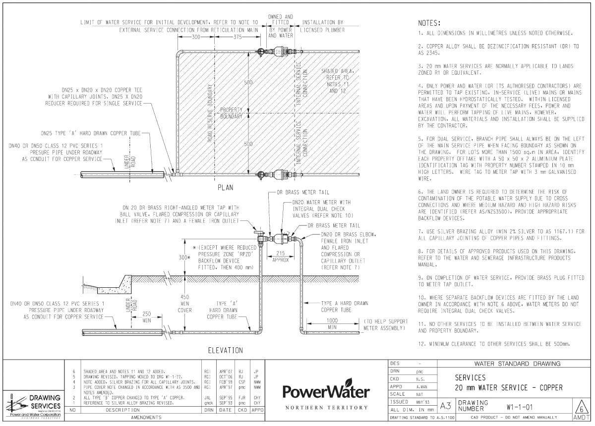
Water Service Drawing (Courtesy of Power and Water Corporation.)
Chapter Summary
• Steel and wrought iron pipes are commonly used for water, steam, oil, and gas. Steel provides the strength necessary for the high pressures commonly associated with these substances.
• Cast iron is primarily used for water, gas, and waste. Cast iron is durable for all but the highest pressures. Cast iron pipe typically uses threaded fittings.
• Copper tubing is typically used for water and compressed air. Copper tubing can be connected with solder joints or with compression fittings.
• Plastic pipe and fittings are lightweight, corrosion resistant, and have a smooth inner surface. They are often used as a substitute for metallic pipe.
• Single-line drawings and simplified symbols are commonly used to represent pipes and fittings on a pipe drawing. Piping drawings are usually not drawn to scale.
• Valves control the flow of material through a pipe.
• A library of computer piping symbols can speed the creation and modification of CAD piping drawings.
Review Questions
1. Which pipe material would be used for the highest pressures?
2. Which types of fittings are commonly used with cast iron pipe? With copper tubing?
3. Which fitting would join two pipes at 90° or 45°?
4. Which fitting would join two pipes at 180°?
5. Which fitting would join four pipes together at one joint?
6. Which fitting would connect two pipes of different diameter?
7. What is the purpose of a valve?
8. How is flow direction indicated on a piping drawing?
9. Why is a library of piping symbols important when drawing with CAD?
10. Draw and label five single-line piping symbols.
Chapter Exercises
Exercise 20.1 Make a double-line drawing, similar to Figure 20.2a and Figure 20.8, showing the following fittings: a union, a 45° Y bend, an eccentric reducer, a globe valve, a tee, a stopcock, and a 45° ell. Use 1/2″ and 1″ wrought steel pipe and 125 lb cast iron screwed fittings.
Exercise 20.2 Make a single-line drawing, similar to Figure 20.2b, showing the following fittings: a 45° ell, a union, a 45° Y bend, an eccentric reducer, a tee, a reducer, a gate valve, a plug, a cap, and a cross.

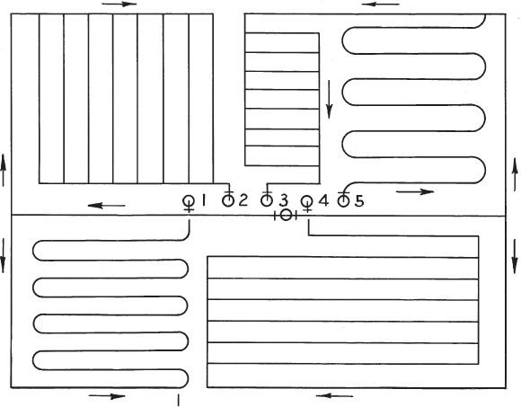
Exercise 20.3 Make a single-line drawing of the system of pipe coils and grids shown above. Show, by their respective standard symbols, the elbows and tees that must be used to connect pipes meeting at right angles if welding is not used to make the joints.
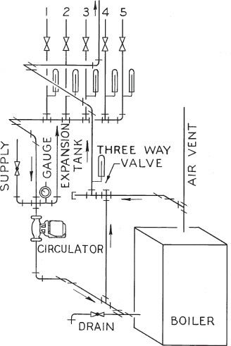
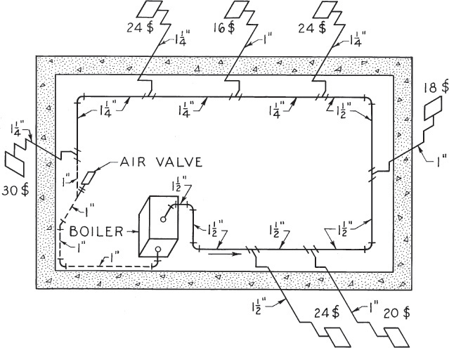
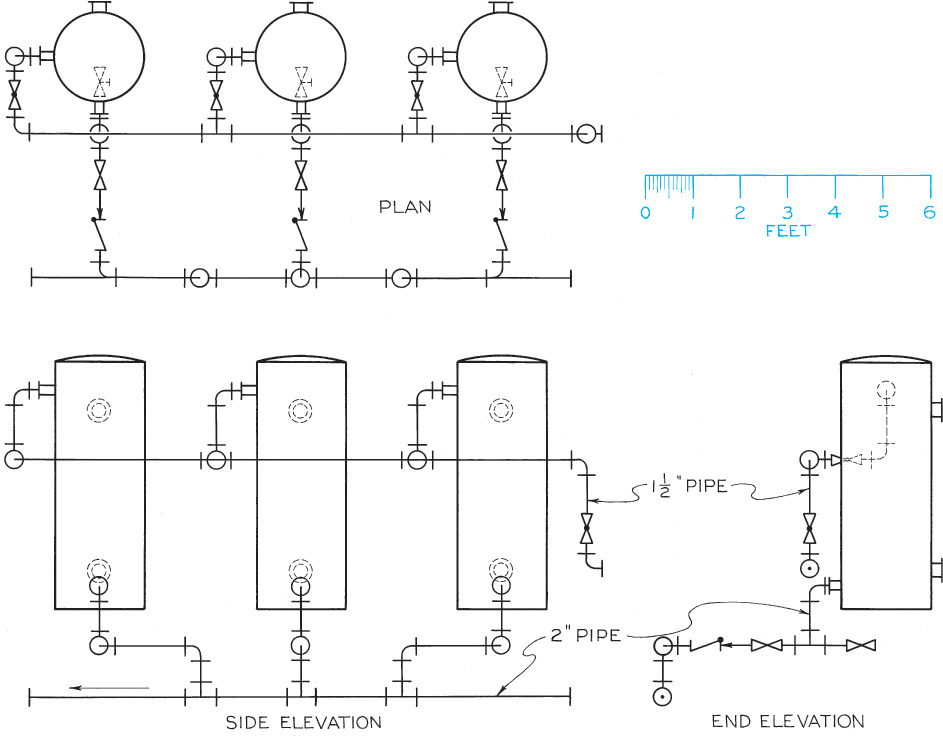
Exercise 20.4 Make an oblique projection, similar to that shown above, of the one-pipe steam heating system shown. Show the pipes by single lines, the fittings by their standard symbols, and the boiler and radiators as parallelepipeds.
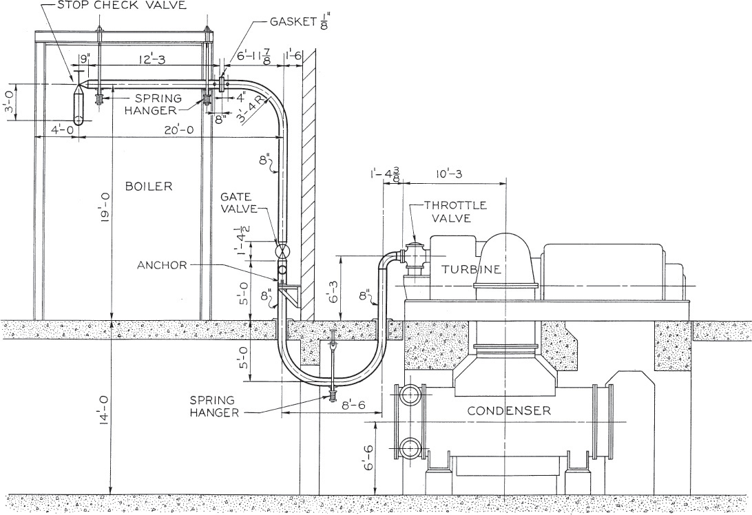
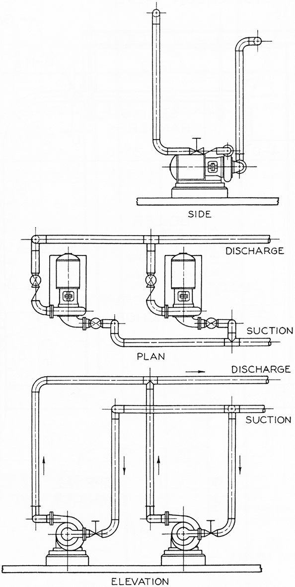
Exercise 20.5 Make a single-line isometric drawing of the piping layout shown. Use a scale of 3/4″ = 1′−0. (Make the drawing similar to the isometric layout shown in Exercise 20.6.)
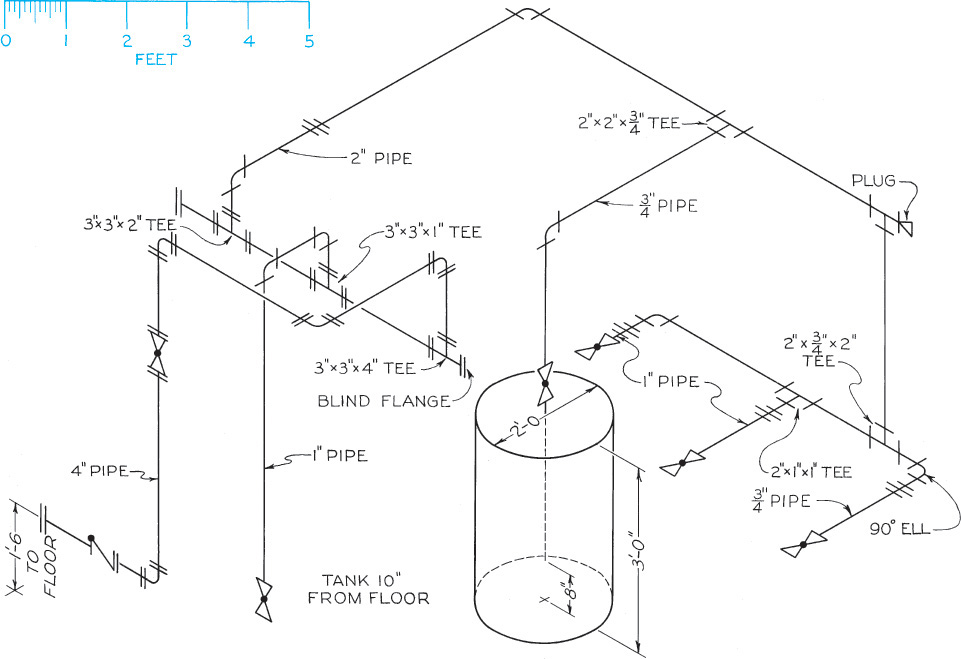
Exercise 20.6 Make a single-line multiview drawing of the piping layout shown above. Use a scale of 1″ = 1′−0. (This drawing should be similar to the piping layout in Exercise 20.5.)
Exercise 20.7 Make a double-line multiview drawing of the piping layout in Exercise 20.5 to a scale of your own selection. (This drawing should be similar to the two-line piping drawing in Figure 20.2a, but you will create front, top, and side views.)
Exercise 20.8 Make a double-line multiview drawing of the piping layout in Exercise 20.6 to a scale of your own selection. Use Schedule 80 wrought steel pipe throughout, with Class 250 cast iron flanged fittings where pipe is larger than 2″ and Class 250 cast iron screwed fittings where pipe is 2″ and smaller. (This drawing should be similar to the two-line piping drawing in Figure 20.2a, but you will create front, top, and side views.)