
- Deploying a multi-tiered web application in AWS with Terraform
- Setting project variables in variables definition files
- Organizing code with nested modules
- Using modules from the Terraform Registry
- Passing data between modules using input variables and output values
Highly available, scalable web hosting has been a complex and expensive proposition until relatively recently. It wasn’t until AWS released its Elastic Compute Cloud (EC2) service in 2006 that things started changing for the better. EC2 was the first pay-as-you-go service that enabled customers to provision to nearly infinite capacity on demand. As great as EC2 was, a significant tooling gap existed that could not be met with CloudFormation or existing configuration management tools. Terraform was designed to fill the tooling gap, and we are now going to look at how Terraform solves this problem. In this chapter, we deploy a highly available and scalable multi-tiered web application in AWS.
Before we begin, what is meant by a multi-tiered application? Multi-tier simply refers to a software system that is divided into logical layers, like a cake (see figure 4.1). A three-tiered design is popular because it imposes a clear boundary between the frontend and backend. The frontend is what people see and is called the UI or presentation layer. The backend is what people don’t see and is made up of two parts: the application layer (typically a REST API) and the persistent storage or data access layer (such as a database).
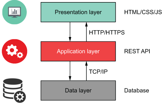
Figure 4.1 Typical multi-tiered web application
In this chapter, we’ll deploy a three-tiered web application for a social media site geared toward pet owners. A preview of the deployed application is shown in figure 4.2.
Note If you are interested in comparable serverless or containerized deployments, stay tuned, because we cover them in chapters 5, 7, and 8.

Figure 4.2 Preview of the deployed web application
4.1 Architecture
From an architectural point of view, we’re going to put some EC2 instances in an autoscaling group and then put that behind a load balancer (see figure 4.3). The load balancer will be public-facing, meaning it can be accessed by anyone. In contrast, both the instances and database will be on private subnets with firewall rules dictated by security groups.
Note If you have used AWS, this should be a familiar architecture pattern. If not, don’t worry; it won’t stop you from completing the chapter.

Figure 4.3 Architecture diagram for the multi-tiered web application
Note We aren’t going to configure Secure Sockets Layer (SSL) / Transport Layer Security (TLS) on the load balancer since doing so requires validating a domain name, but know that it is possible to do by using Terraform resources for Amazon Certificate Manager (ACM) and Route53.
Since this is a non-trivial deployment, there are many ways to go about implementation, but I suggest splitting things into smaller components that are easier to reason about. For this scenario, we will split the project into three major components:
-
Networking—All networking-related infrastructure, including the VPC, subnets, and security groups
-
Autoscaling—Load balancer, EC2 autoscaling group, and launch template resources
These three major components are illustrated in figure 4.4.

Figure 4.4 Infrastructure split into three major components
In Terraform, the components into which resources are organized using this approach are called modules. Before we go any further, let’s formally introduce modules.
4.2 Terraform modules
Modules are self-contained packages of code that allow you to create reusable components by grouping related resources together. You don’t have to know how a module works to be able to use it; you just have to know how to set inputs and outputs. Modules are useful tools for promoting software abstraction and code reuse.
4.2.1 Module syntax
When I think about modules, the analogy of building with toy blocks always comes to mind. Blocks are simple elements, yet complexity can emerge from the way they are joined. If resources and data sources are the individual building blocks of Terraform, then modules are prefabricated groupings of many such blocks. Modules can be dropped into place with little effort; see figure 4.5.

Figure 4.5 Using a module in Terraform is like using a prefabricated building block component.
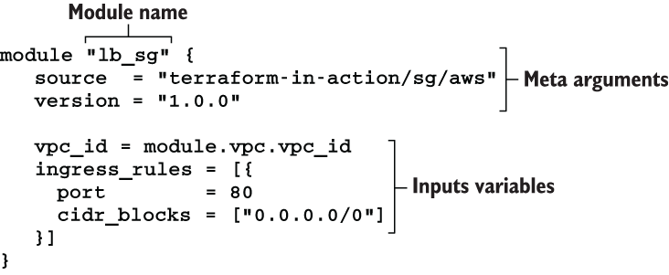
The syntax for module declarations is shown in figure 4.6. They resemble resource declarations because they have meta arguments, inputs, variables, and a name.
4.2.2 What is the root module?
Every workspace has a root module; it’s the directory where you run terraform apply. Under the root module, you may have one or more child modules to help you organize and reuse configuration. Modules can be sourced either locally (meaning they are embedded within the root module) or remotely (meaning they are downloaded from a remote location as part of terraform init). In this scenario, we will use a combination of locally and remotely sourced modules.
As a reminder, we will have three components: networking, database, and autoscaling. Each component will be represented by a module in Terraform. Figure 4.7 shows the overall module structure for the scenario.

Figure 4.7 Overall module structure with nested child modules
Some child modules have their own child modules (for example, the networking and autoscaling modules). This children-within-children module pattern is called nested modules.
4.2.3 Standard module structure
HashiCorp strongly recommends that every module follow certain code conventions known as the standard module structure (www.terraform.io/docs/modules/index.html #standard-module-structure). At a minimum, this means having three Terraform configuration files per module:
NOTE versions.tf, providers.tf, and README.md are considered required files in the root module. We will discuss this more in chapter 6.
Figure 4.8 details the overall module structure, taking into consideration additional files required as part of the standard module structure. In the next few sections, we write the configuration code for the root and child modules before deploying to AWS.

Figure 4.8 Detailed module structure
4.3 Root module
The root module is the top-level module. It’s where user-supplied input variables are configured and where Terraform commands such as terraform init and terraform apply are run. In our root module, there will be three input variables and two output values. The three input variables are namespace, ssh_keypair, and region, and the two output values are db_password and lb_dns_name; see figure 4.9.
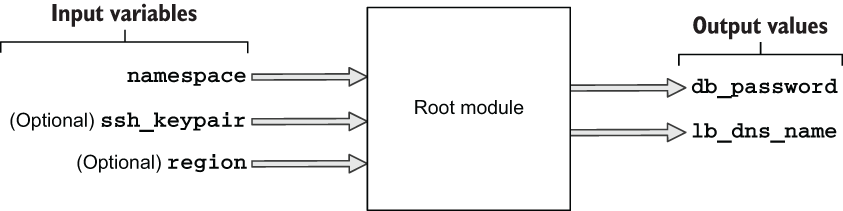
Figure 4.9 Input variables and output values for the root module
A user of the root module only needs to set the namespace variable to deploy the project since the other two variables are marked as optional. The output values they’ll receive contain the provisioned load balancer’s DNS name (lb_dns_name) and the database password (db_password). The load balancer DNS name is important because it’s how the user will navigate to the website from a web browser.
Our root module consists of six files. Here’s what they are and what they are for:
In the next section, we go through the code that’s in these files.
4.3.1 Code
Let’s start with variables.tf. If you haven’t already done so, create a new empty directory for your code to live in; in this directory, create a variables.tf file.
variable "namespace" {
  description = "The project namespace to use for unique resource naming"
  type        = string
}

variable "ssh_keypair" {
  description = "SSH keypair to use for EC2 instance"
  default     = null                                       ❶
  type        = string
}

variable "region" {
  description = "AWS region"
  default     = "us-west-2"
  type        = string
}
❶ Null is useful for optional variables that don’t have a meaningful default value.
We set variables by using a variables definition file. The variables definition file allows you to parameterize configuration code without having to hardcode default values. It uses the same basic syntax as Terraform configuration but consists only of variable names and assignments. Create a new file called terraform.tfvars, and insert the code from listing 4.2. This sets the namespace and region variables in variables.tf.
Note We won’t set ssh_keypair because it requires having a generated SSH keypair. Refer to chapter 9 for an example of how to do this.
namespace = "my-cool-project"
region    = "us-west-2"
The region variable configures the AWS provider. We can reference this variable in the provider declaration. Do this by creating a new providers.tf file and copying into it the following code.
aws" {
  region  = var.region
}
TIP You can also set the profile attribute in the AWS provider declaration, if you are not using the default profile or environment variables to configure credentials.
The namespace variable is a project identifier. Some module authors eschew namespace in favor of two variables: for example, project_name and environment. Regardless of whether you choose one or two variables for your project identifier, all that matters is that your project identifier is unique and descriptive, such as tia-chapter4-dev.
We’ll pass namespace into each of the three child modules. Although we have not yet fleshed out what the child modules do, we can stub them with the information we do know. Create a main.tf file with the code from the next listing.
module "autoscaling" {
  source      = "./modules/autoscaling"          ❶
  namespace   = var.namespace                    ❷
}

module "database" {
  source    = "./modules/database"               ❶
  namespace = var.namespace                      ❷
}

module "networking" {
  source    = "./modules/networking"             ❶
  namespace = var.namespace                      ❷
}
❶ Nested child modules are sourced from a local modules directory.
❷ Each module uses var.namespace for resource naming.
Now that we have stubbed out the module declarations in main.tf, we will stub out the output values in a similar fashion. Create an outputs.tf file with the following code.
ut "db_password" {
"tbd"
}
output "lb_dns_name" {
  value = "tbd"
}
The last thing we need to do is lock in the provider and Terraform versions. Normally, I would recommend waiting until after running terraform init to do this step so you simply note the provider versions that are downloaded and use those; but we will version-lock now since I’ve done this step ahead of time. Create versions.tf with the code from the next listing.
terraform {
  required_version = ">= 0.15"
  required_providers {
    aws = {
      source  = "hashicorp/aws"
      version = "~> 3.28"
    }
    random = {
      source  = "hashicorp/random"
      version = "~> 3.0"
    }
    cloudinit = {
      source  = "hashicorp/cloudinit"
      version = "~> 2.1"
    }
  }
}
4.4 Networking module
The networking module is the first of three child modules we’ll look at. This module is responsible for provisioning all networking-related components of the web app, including Virtual Private Cloud (VPC), subnets, the internet gateway, and security groups. Overall inputs and outputs are shown in figure 4.10.

Figure 4.10 Overall inputs and outputs of the networking module
From a black box perspective, you can simply treat modules as functions with side effects (i.e. nonpure functions). We already know what the module's inputs and outputs are, but what are the side effects? Side effects are just the resources provisioned as a result of terraform apply (see figure 4.11).
Note Some of the resources provisioned by the networking module are not covered under the AWS free tier.

Figure 4.11 Managed resources provisioned by the networking module

Figure 4.12 Dependency diagram for the networking module
Create a new directory with the path ./modules/networking. In this directory, create three files: variables.tf, main.tf, and outputs.tf. We’ll start with variables.tf: copy the following code into it.
variable "namespace" {
    type = string
}
Before I throw the main code at you, I want to explain how it is structured. Generally, resources declared at the top of the module have the fewest dependencies, while resources declared at the bottom have the most dependencies. Resources are declared so that they feed into each other, one after another (this is also sometimes called resource chaining). Refer to figure 4.12 for a visual representation.
Note Some people like to declare security groups in the module where they will be used instead of in a separate networking module. It’s entirely a matter of preference; do what makes sense to you.
The next listing has the code for main.tf; copy it into your file. Don’t worry too much about understanding all of the code; just pay attention to how everything connects.
data "aws_availability_zones" "available" {}

module "vpc" {                                                             ❶
  source                           = "terraform-aws-modules/vpc/aws"
  version                          = "2.64.0"
  name                             = "${var.namespace}-vpc"
  cidr                             = "10.0.0.0/16"
  azs                              = data.aws_availability_zones.available
                                                            ➥ .names
  private_subnets                  = ["10.0.1.0/24", "10.0.2.0/24",
                                                            ➥ "10.0.3.0/24"]
  public_subnets                   = ["10.0.101.0/24", "10.0.102.0/24",
                                                            ➥ "10.0.103.0/24"]
  database_subnets                 = ["10.0.21.0/24", "10.0.22.0/24",
                                                            ➥ "10.0.23.0/24"]

  create_database_subnet_group     = true
  enable_nat_gateway               = true
  single_nat_gateway               = true
}

module "lb_sg" {
terraform-in-action/sg/aws"
  vpc_id = module.vpc.vpc_id
  ingress_rules = [{
    port        = 80
    cidr_blocks = ["0.0.0.0/0"]
  }]
}

module "websvr_sg" {
  source = "terraform-in-action/sg/aws"                                    ❷
  vpc_id = module.vpc.vpc_id
  ingress_rules = [
    {
      port            = 8080
      security_groups = [module.lb_sg.security_group.id]
    },
    {
      port        = 22                                                     ❸
      cidr_blocks = ["10.0.0.0/16"]                                        ❸
    }
  ]
}

module "db_sg" {
  source = "terraform-in-action/sg/aws"
  vpc_id = module.vpc.vpc_id
  ingress_rules     = [{
    port            = 3306
    security_groups = [module.websvr_sg.security_group.id]
  }]
}
❶ AWS VPC module published in the Terraform Registry
❷ Security group module published by me
❸ Allows SSH for a potential bastion host
It should be evident that the module is mostly made up of other modules. This pattern is known as software componentization: the practice of breaking large, complex code into smaller subsystems. For example, instead of writing the code for deploying a VPC ourselves, we are using a VPC module maintained by the AWS team. Meanwhile, the security group module is maintained by me. Both modules can be found on the public Terraform Registry, which we talk more about in chapter 6.
Note Since I don’t own the VPC module, I have version-locked it to ensure compatibility when you run the code. In this book, I do not version-lock my own modules because I always want you to download the latest version, in case I have to patch something.
Finally, the code for outputs.tf is shown in listing 4.9. Notice that the vpc output passes a reference to the entire output of the VPC module. This allows us to be succinct in the output code, especially when passing data through multiple layers of nested modules. Also notice that the sg output is made up of a new object containing the IDs of the security groups. This pattern is useful for grouping related attributes from different resources in a single output value.
Tip Grouping related attributes into a single output value helps with code organization.
output "vpc" {
  value = module.vpc                                      ❶
}

output "sg" {
  value = {                                               ❷
    lb     = module.lb_sg.security_group.id               ❷
    db     = module.db_sg.security_group.id               ❷
    websvr = module.websvr_sg.security_group.id           ❷
  }                                                       ❷
}
❶ Passes a reference to the entire vpc module as an output
❷ Constructs a new object containing the ID for each of the three security groups
4.5 Database module
The database module does exactly what you would expect: it provisions a database. The inputs and outputs are shown in figure 4.13.
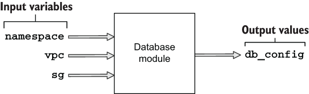
Figure 4.13 Inputs and outputs of the database module
This module creates only one managed resource, so the side effect diagram is simple compared to that of the networking module (see figure 4.14). We didn’t write this one first because the database module has an implicit dependency on the networking module, and it requires references to the VPC and database security groups.

Figure 4.14 Managed resources provisioned by the database module
Figure 4.15 shows the dependency diagram. It’s concise, as only two resources are being created, and one of them is local-only.
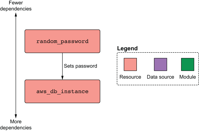
Figure 4.15 Dependency diagram for the database module
4.5.1 Passing data from the networking module
The database module requires references to VPC and database security group ID. Both of these are declared as outputs of the networking module. But how do we get this data into the database module? By “bubbling up” from the networking module into the root module and then “trickling down” into the database module; see figure 4.16.

Figure 4.16 Data flow as the database’s security group ID makes its way from the networking module into the database module
TIP Because passing data between modules is tedious and hurts readability, you should avoid doing so as much as possible. Organize your code such that resources that share a lot of data are closer together or, better yet, part of the same module.
The root module isn’t doing a lot except declaring component modules and allowing them to pass data between themselves. You should know that data passing is a two-way street, meaning two modules can depend on each other, as long as a cyclical dependency isn’t formed; see figure 4.17. I don’t use interdependent modules anywhere in this book because I think it’s a bad design pattern.
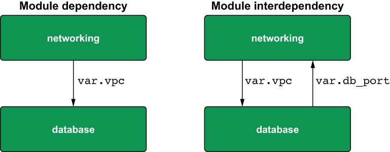
Figure 4.17 Dependent vs. interdependent modules
Tip Avoid having interdependent modules—they make things confusing!
Let’s get down to business. Update the database module declaration in the root module to include a reference to the networking module outputs (see listing 4.10). This takes care of bubbling the networking module's outputs up to the root level and then trickling them down as input variables in the database module.
Listing 4.10 main.tf in the root module
module "autoscaling" {
  source      = "./modules/autoscaling"
  namespace   = var.namespace
}

module "database" {
  source    = "./modules/database"
  namespace = var.namespace

  vpc = module.networking.vpc           ❶
  sg  = module.networking.sg            ❶
}

module "networking" {
  source    = "./modules/networking"
  namespace = var.namespace
}
❶ Data bubbles up from the networking module and trickles down into the database module.
Next, we have to create the database module. Create a ./modules/database directory, and create three files in it: variables.tf, main.tf, and outputs.tf. The variables.tf file contains the input variables for namespace, vpc, and sg.
variable "namespace" {
  type = string
}

variable "vpc" {
  type = any           ❶
}

variable "sg" {
  type = any           ❶
}
❶ A type constraint of “any” type means Terraform will skip type checking.
In this code, we specify the type of vpc and sg as any. This means we allow any kind of data structure to be passed in, which is convenient for times when you don’t care about strict typing.
Warning While it may be tempting to overuse the any type, doing so is a lazy coding habit that will get you into trouble more often than not. Only use any when passing data between modules, never for configuring the input variables on the root module.
4.5.2 Generating a random password
Now that we have declared our input variables, we can reference them in the configuration code. The following listing shows the code for main.tf. In addition to the database, we also generate a random password for the database with the help of our old friend, the Random provider.
resource "random_password" "password" {                           ❶
  length           = 16
  special          = true
  override_special = "_%@/'""
}

resource "aws_db_instance" "database" {
  allocated_storage      = 10
  engine                 = "mysql"
  engine_version         = "8.0"
  instance_class         = "db.t2.micro"
  identifier             = "${var.namespace}-db-instance"
  name                   = "pets"
  username               = "admin"
  password               = random_password.password.result
  db_subnet_group_name   = var.vpc.database_subnet_group          ❷
  vpc_security_group_ids = [var.sg.db]                            ❷
  skip_final_snapshot    = true
}
❶ Uses the random provider to create a 16-character password
❷ These values came from the networking module.
Next, construct an output value consisting of the database configuration required by the application to connect to the database (listing 4.13). This is done similarly to what we did with the sg output of the networking module. In this situation, instead of aggregating data from multiple resources into one, we use this object to bubble up just the minimum amount of data that the autoscaling module needs to function. This is in accordance with the principle of least privilege.
output "db_config" {
  value = {
    user     = aws_db_instance.database.username          ❶
    password = aws_db_instance.database.password          ❶
    database = aws_db_instance.database.name              ❶
    hostname = aws_db_instance.database.address           ❶
    port     = aws_db_instance.database.port              ❶
  }
}
❶ All the data in db_config comes from select output of the aws_db_instance resource.
Tip To reduce security risk, never grant more access to data than is needed for legitimate purposes.
Changing back to the root module, let’s add some plumbing: we can make the database password available to the CLI user by adding an output value in outputs.tf. Doing so makes the database password appear in the terminal when terraform apply is run.
Listing 4.14 outputs.tf in the root module
output "db_password" {
  value = module.database.db_config.password
}

output "lb_dns_name" {
  value = "tbd"
}
4.6 Autoscaling module
Luckily, I have saved the most complex module for last. This module provisions the autoscaling group, load balancer, Identity and Access Management (IAM) instance role, and everything else the web server needs to run. The inputs and outputs for the module are shown in figure 4.18. Figure 4.19 illustrates the resources being deployed by this module.

Figure 4.18 Inputs and outputs of the autoscaling module
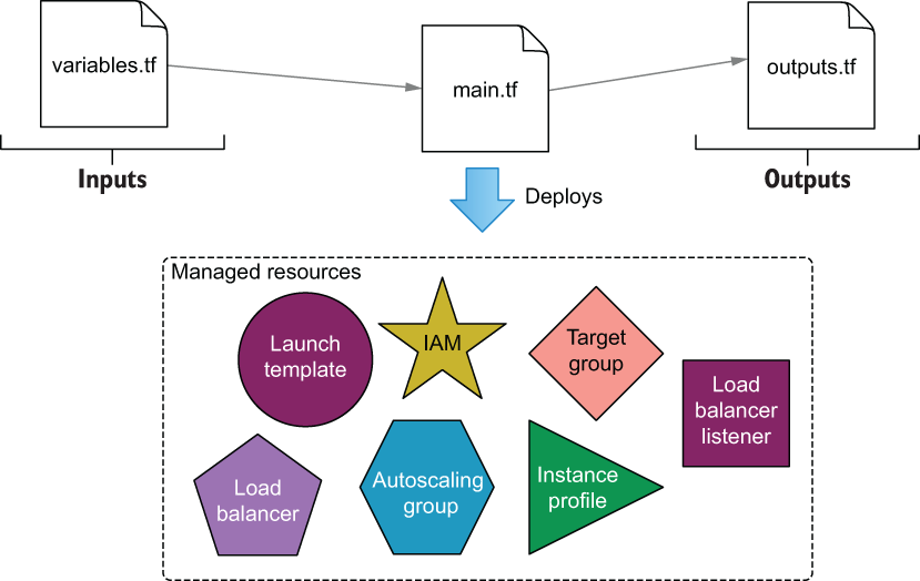
Figure 4.19 Managed resources provisioned by the autoscaling module
As we did in the networking module, we’ll use helper child modules to provision resources that would otherwise take many more lines of code. Specifically, we’ll do this for the IAM instance profile and load balancer.
4.6.1 Trickling down data
The three input variables of the autoscaling module are vpc, sg, and db_config. vpc and sg come from the networking module, while db_config comes from the database module. Figure 4.20 shows how data bubbles up from the networking module and trickles down into the application load balancer (ALB) module.
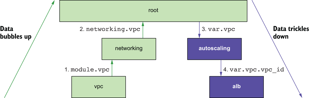
Figure 4.20 Data flow as the vpc ID makes its way from the VPC module to the ALB module
Similarly, db_config bubbles up from the database module and trickles down into the autoscaling module, as shown in figure 4.21. The web application uses this configuration to connect to the database at runtime.
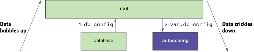
Figure 4.21 Data flow as db_config makes its way from the database module to the autoscaling module
The first thing we need to do is update main.tf in the root module to trickle data down into the autoscaling module.
Listing 4.15 main.tf in the root module
module "autoscaling" {
  source      = "./modules/autoscaling"
  namespace   = var.namespace
  ssh_keypair = var.ssh_keypair                   ❶
                                                  ❶
  vpc       = module.networking.vpc               ❶
  sg        = module.networking.sg                ❶
  db_config = module.database.db_config           ❶
}

module "database" {
  source    = "./modules/database"
  namespace = var.namespace

  vpc = module.networking.vpc
  sg  = module.networking.sg
}

module "networking" {
  source    = "./modules/networking"
  namespace = var.namespace
}
❶ input arguments for the autoscaling module, set by other module’s outputs
As before, the module’s input variables are declared in variables.tf. Create a ./modules/autoscaling directory, and in it create variables.tf. The code for variables.tf is shown next.
variable "namespace" {
  type = string
}

variable "ssh_keypair" {
  type = string
}

variable "vpc" {
  type = any
}

variable "sg" {
  type = any
}

variable "db_config" {
  type = object(                  ❶
    {                             ❶
      user     = string           ❶
      password = string           ❶
      database = string           ❶
      hostname = string           ❶
      port     = string           ❶
    }                             ❶
  )                               ❶
}
❶ Enforces a strict type schema for the db_config object. The value set for this variable must implement the same type schema.
4.6.2 Templating a cloudinit_config
We are going to use a cloudinit_config data source to create the user data for our launch template. Again, the launch template is just a blueprint for the autoscaling group, as it bundles together user data, the AMI ID, and various other metadata. Meanwhile, the autoscaling group has a dependency on the load balancer because it needs to register itself as a target listener. The dependency diagram for the autoscaling module is shown in figure 4.22.

Figure 4.22 Dependency diagram for the autoscaling module
Following is the code for main.tf. Create this file, and copy in the code.
module "iam_instance_profile" {
  source  = "terraform-in-action/iip/aws"
  actions = ["logs:*", "rds:*"]                                            ❶
}

data "cloudinit_config" "config" {
  gzip          = true
  base64_encode = true
  part {
    content_type = "text/cloud-config"
    content      = templatefile("${path.module}/cloud_config.yaml",
var.db_config)                                                             ❷
  }
}

data "aws_ami" "ubuntu" {
  most_recent = true
  filter {
    name   = "name"
    values = ["ubuntu/images/hvm-ssd/ubuntu-bionic-18.04-amd64-server-*"]
  }
  owners = ["099720109477"]
}

resource "aws_launch_template" "webserver" {
  name_prefix   = var.namespace
  image_id      = data.aws_ami.ubuntu.id
  instance_type = "t2.micro"
  user_data     = data.cloudinit_config.config.rendered
  key_name      = var.ssh_keypair
  iam_instance_profile {
    name = module.iam_instance_profile.name
  }
  vpc_security_group_ids = [var.sg.websvr]
}

resource "aws_autoscaling_group" "webserver" {
  name                = "${var.namespace}-asg"
  min_size            = 1
  max_size            = 3
  vpc_zone_identifier = var.vpc.private_subnets
  target_group_arns   = module.alb.target_group_arns
  launch_template {
    id      = aws_launch_template.webserver.id
    version = aws_launch_template.webserver.latest_version
  }
}

module "alb" {
  source             = "terraform-aws-modules/alb/aws"
  version            = "~> 5.0"
  name               = var.namespace
  load_balancer_type = "application"
  vpc_id             = var.vpc.vpc_id
  subnets            = var.vpc.public_subnets
  security_groups    = [var.sg.lb]

  http_tcp_listeners = [
    {
      port               = 80,                                             ❸
      protocol           = "HTTP"
      target_group_index = 0
    }
  ]

  target_groups = [
    { name_prefix      = "websvr",
      backend_protocol = "HTTP",
      backend_port     = 8080
      target_type      = "instance"
    }
  ]
}
❶ The permissions are too open for a production deployment but good enough for dev.
❷ Content for the cloud init configuration comes from a template file.
❸ The load balancer listens on port 80, which is mapped to 8080 on the instance.
Warning Exposing port 80 over HTTP for a publicly facing load balancer is unacceptable security for production-level applications. Always use port 443 over HTTPS with an SSL/TLS certificate!
The cloud init configuration is templated using the templatefile function, which we previously saw in chapter 3. This function accepts two arguments: a path and a variable object. Our template’s file path is ${path.module}/cloud_config.yaml, which is a relative module path. This result of this function is passed into the cloudinit_config data source and then used to configure the aws_launch _template resource. The code for cloud_config.yaml is shown in listing 4.18.
TIP Template files can use any extension, not just .txt or .tpl (which many people use). I recommend choosing the extension that most clearly indicates the contents of the template file.
Listing 4.18 cloud_config.yaml
#cloud-config
write_files:
  -   path: /etc/server.conf
      owner: root:root
      permissions: "0644"
      content: |
        {
          "user":  "${user}",
          "password": "${password}",
          "database": "${database}",
          "netloc": "${hostname}:${port}"
        }
runcmd:
curl -sL https://api.github.com/repos/terraform-in-action/vanilla-webserver-
       ➥ src/releases/latest | jq -r ".assets[].browser_download_url" |
       ➥ wget -qi -
  - unzip deployment.zip
  - ./deployment/server
packages:
  - jq
  - wget
  - unzip
Warning It is important that you copy this file exactly as is, or the web server will fail to start.
This is a fairly simple cloud init file. All it does is install some packages, create a configuration file (/etc/server.conf), fetch application code (deployment.zip) and start the server.
Finally, the output of the module is lb_dns_name. This output is bubbled up to the root module and simply makes it easier to find the DNS name after deploying.
output "lb_dns_name" {
  value = module.alb.this_lb_dns_name
}
We also have to update the root module to include a refence to this output.
Listing 4.20 outputs.tf in the root module
output "db_password" {
  value = module.database.db_config.password
}

output "lb_dns_name" {
  value = module.autoscaling.lb_dns_name
}
4.7 Deploying the web application
We’ve created a lot of files, which is not unusual with Terraform, especially when separating code into modules. For reference, the current directory structure is as follows:
$ tree
.
├── main.tf
├── modules
│   ├── autoscaling
│   │    ├── cloud_config.yaml
│   │    ├── main.tf
│   │    ├── outputs.tf
│   │    └── variables.tf
│   ├── database
│   │    ├── main.tf
│   │    ├── outputs.tf
│   │    └── variables.tf
│   └── networking
│   │    ├── main.tf
│   │    ├── outputs.tf
│   │    └── variables.tf
├── outputs.tf
├── providers.tf
├── terraform.tfvars
├── variables.tf
└── versions.tf

4 directories, 16 files
At this point, we’re ready to deploy the web application into AWS. Change into the root module directory, and run terraform init followed by terraform apply -auto-approve. After waiting ~10-15 minutes (it takes a while for VPC and EC2 resources to be created), the tail of your output will be something like this:
module.autoscaling.aws_autoscaling_group.webserver: Still creating...
[10s elapsed]
module.autoscaling.aws_autoscaling_group.webserver: Still creating...
[20s elapsed]
module.autoscaling.aws_autoscaling_group.webserver: Still creating...
[30s elapsed]
module.autoscaling.aws_autoscaling_group.webserver: Still creating...
[40s elapsed]
module.autoscaling.aws_autoscaling_group.webserver: Creation complete after
41s [id=my-cool-project-asg]

Apply complete! Resources: 40 added, 0 changed, 0 destroyed.

Outputs:

db_password = "oeZDaIkrM7om6xDy"                                           ❶
lb_dns_name = "my-cool-project-793358543.us-west-2.elb.amazonaws.com"      ❶
❶ Your db_password and lb_dns_name will be different from mine.
Now copy the value of lb_dns_name into your web browser of choice to navigate to the website.
Note If you get a 502 “bad gateway” error, wait a few more seconds before trying again, as the web server hasn’t finished initializing yet. If the error persists, your cloud init file is most likely malformed.
Figure 4.23 shows the final website. You can click the + button to add pictures of your cats or other animals to the database, and the animals you add will be viewable by anyone who visits the website.

Figure 4.23 Deployed web app with no pets added yet
When you’re done, don’t forget to take down the stack to avoiding paying for infrastructure you don’t need (again, this will take ~10-15 minutes). Do this with terraform destroy -auto-approve. The tail of your destroy run will be as follows:
module.networking.module.vpc.aws_internet_gateway.this[0]:
➥ Destruction complete after 11s
module.networking.module.vpc.aws_vpc.this[0]:
➥ Destroying... [id=vpc-0cb1e3df87f1f65c8]
module.networking.module.vpc.aws_vpc.this[0]: Destruction complete after 0s

Destroy complete! Resources: 40 destroyed.
4.8 Fireside chat
In this chapter, we designed and deployed a Terraform configuration for a multi-tiered web application in AWS. We broke out individual components into separate modules, which resulted in several layers of nested modules. Nested modules are a good design for complex Terraform projects, as they promote software abstraction and code reuse, although passing data can become tedious. In the next chapter, we investigate an alternative to nested modules: flat modules. A generalized way to structure nested module hierarchies is shown in figure 4.24.
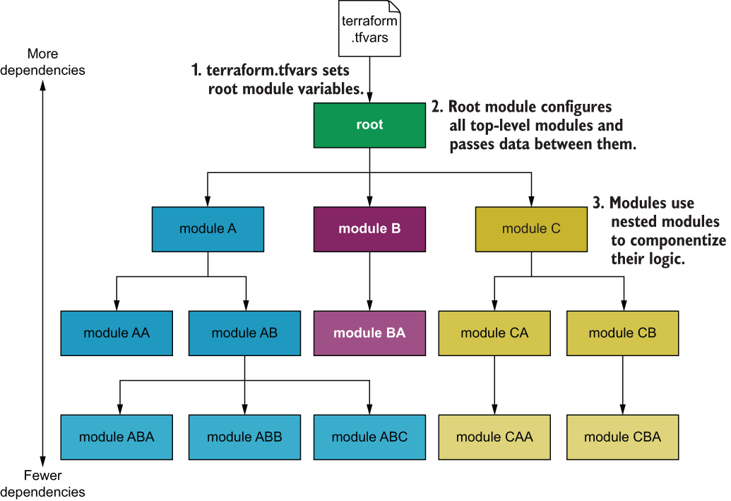
Figure 4.24 Generalized nested module hierarchy
Summary
-
Complex projects, such as multi-tiered web applications in AWS, are easy to design and deploy with the help of Terraform modules.
-
The root module is the main entry point for your project. You configure variables at the root level by using a variables definition file (terraform.tfvars). These variables are then trickled down as necessary into child modules.
-
Nested modules organize code into child modules. Child modules can be nested within other child modules without limit. Generally, you don’t want your module hierarchy to be more than three or four levels deep, because it makes it harder to understand.
-
Many people have published modules in the public Terraform Registry. You can save a lot of time by using these open source modules instead of writing comparable code yourself; all it takes is learning how to use the module interface.
-
Data is passed between modules using bubble-up and trickle-down techniques. Since this can result in a lot of boilerplate, it’s a good idea to optimize your code so that minimal data needs to be passed between modules.