
Chapter 6. Connections
Connections are specialized figures that implement the Connection interface and draw a line between two locations on the canvas, typically “connecting” two figures. You could create your own implementation of the Connection interface, but most developers use the PolylineConnection class provided by Draw2D. Since many diagrams use connections to indicate direction, connections have a beginning, called the source, and an end, called the target. Both the source and the target must have their own anchor, which is responsible for calculating the location where the connection starts and ends respectively. Typically, an anchor is associated with an owner figure, but anchors can be fixed to a point on the canvas instead.
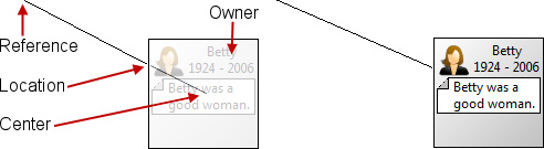
In the GenealogyView we use a PolylineConnection to connect the MarriageFigure and the PersonFigure. A ChopboxAnchor is used to associate one end of the connection with the PersonFigure; thus in this case the ChopboxAnchor’s owner is an instance of PersonFigure (see Figure 6–1). When the connection is drawn, the anchor is passed the reference location and asked to calculate the location for its end of the connection. The ChopboxAnchor returns a location that is the intersection of the line formed by the reference point and the center point of the ChopboxAnchor’s owner, and the edge of the ChopboxAnchor’s owner’s bounding box (see Section 6.1.1 on page 70).
Figure 6–1. Anchor components.
6.1 Common Anchors
In addition to the ChopboxAnchor mentioned above, Draw2D provides a number of common anchors. Each type of anchor is appropriate for a different geometric situation; a ChopboxAnchor is appropriate for a rectangular figure, whereas an EllipseAnchor is appropriate for an elliptical figure. Each anchor has an owner figure with the exception of XYAnchor, which is used to position a connection to a fixed location on the canvas. The screenshots and code below are taken from the BasicAnchors class (see Section 2.6 on page 20).
6.1.1 ChopboxAnchor
This anchor attaches the connection end point to the figure at the point where the connection intersects with the rectangular bounds of the figure when pointing toward the center of the bounds of the figure (see Figure 6–2).
Figure 6–2. Chopbox anchor examples.
![]()
Connection conn = new PolylineConnection();
conn.setSourceAnchor(new XYAnchor(new Point(10, 10)));
conn.setTargetAnchor(new ChopboxAnchor(rectangleFigure));
root.add(conn);
6.1.2 EllipseAnchor
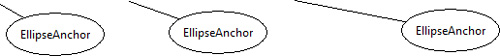
This anchor attaches the connection end point to the figure at the point where the connection intersects the largest ellipse that fits into the bounds of the figure when pointing toward the center of the bounds of the figure (see Figure 6–3).
Figure 6–3. Ellipse anchor examples.
Connection conn = new PolylineConnection();
conn.setSourceAnchor(new XYAnchor(new Point(150, 10)));
conn.setTargetAnchor(new EllipseAnchor(ellipse));
root.add(conn);
6.1.3 LabelAnchor
This anchor attaches the connection end point to the left center edge of a Label (see Figure 6–4).
Figure 6–4. Label anchor examples.
![]()
Connection conn = new PolylineConnection();
conn.setSourceAnchor(new XYAnchor(new Point(10, 110)));
conn.setTargetAnchor(new LabelAnchor(label));
root.add(conn);
6.1.4 XYAnchor
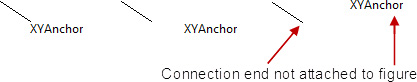
This anchor attaches the connection end point to a fixed point on the canvas (see Figure 6–5).
Figure 6–5. XY anchor examples.
Connection conn = new PolylineConnection();
conn.setSourceAnchor(new XYAnchor(new Point(150, 110)));
conn.setTargetAnchor(new XYAnchor(new Point(180, 130)));
root.add(conn);
6.2 Custom Anchors
The ChopboxAnchor is a good choice for connecting to the edge of a rectangular figure, but what if you want to connect to the center, or connect to the edge of a non-rectangular figure? In these cases, you may want to create your own subclass of AbstractConnectionAnchor.
6.2.1 CenterAnchor
Here we implement a very simplistic anchor that attaches the connection end point to the center of the owner’s bounding box (see Figure 6–6). You can easily modify this anchor to attach the connection end point to various fixed locations on the owner’s bounding box, such as the top right corner, by replacing the getCenter() call with a call to getTopRight().
Figure 6–6. Center anchor examples.
![]()
import org.eclipse.draw2d.*;
import org.eclipse.draw2d.geometry.*;
public final class CenterAnchor extends AbstractConnectionAnchor {
public CenterAnchor(IFigure owner) {
super(owner);
}
public Point getLocation(Point reference) {
return getOwner().getBounds().getCenter();
}
}
6.2.2 MarriageAnchor
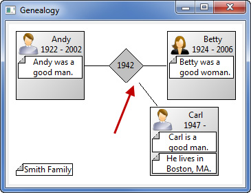
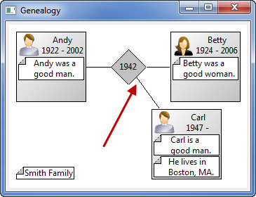
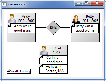
The ChopboxAnchor is perfect for anchoring a connection to the edge of a PersonFigure but not so good for anchoring a connection to the edge of a MarriageFigure (see Figure 6–7). Ideally, we would like the connection to terminate along the edge of the MarriageFigure rather than on the MarriageFigure’s bounding box. This becomes very apparent when one of the PersonFigures is moved off center.
Figure 6–7. Genealogy view showing problem with chopbox anchor.
To fix this, we create a new MarriageAnchor object subclassing AbstractConnectionAnchor similar to the CenterAnchor described above. To implement the MarriageAnchor’s getLocation(...) method, we must calculate and return the intersection of the line segment from the reference location to the figure’s center with the edge of the figure (see Figure 6–8).
Figure 6–8. Diagram showing marriage anchor intersection calculation.

To simplify our calculations, we consider the center of the MarriageFigure to be 0,0 and use screen coordinates where the x-axis increases from left to right and the y-axis increases from top to bottom. Given the reference point Ax,Ay, we know that
x / y = Ax / Ay
and given the Radius of the diamond, we know that
x + y = Radius
With these two equations we can solve for x and y in terms of the reference point Ax,Ay and the Radius of the diamond.
x = Radius * Ax / (Ax + Ay)
y = Radius * Ay / (Ax + Ay)
These two equations allow us to locate the intersection along one of the four sides of the diamond. By taking the absolute value of Ax and Ay and adjusting based upon which quadrant contains the reference point, we can implement the MarriageAnchor’s getLocation(...) method as shown below. We must also catch the edge case where Ax + Ay is zero.
import static c.q.g.figures.MarriageFigure.RADIUS;
public class MarriageAnchor extends AbstractConnectionAnchor {
public MarriageAnchor(IFigure owner) {
super(owner);
}
public Point getLocation(Point reference) {
Point origin = getOwner().getBounds().getCenter();
int Ax = Math.abs(reference.x - origin.x);
int Ay = Math.abs(reference.y - origin.y);
int divisor = Ax + Ay;
if (divisor == 0)
return origin;
int x = (RADIUS * Ax) / divisor;
int y = (RADIUS * Ay) / divisor;
if (reference.x < origin.x)
x = -x;
if (reference.y < origin.y)
y = -y;
return new Point(origin.x + x, origin.y + y);
}
}
For this new class to compile, we add the radius as a constant in the MarriageFigure.
public static final int RADIUS = 26;
Now we can use the new anchor in the GenealogyView. Start by adding two new methods in MarriageFigure that use the new MarriageAnchor.
public PolylineConnection addParent(IFigure figure) {
PolylineConnection connection = new PolylineConnection();
connection.setSourceAnchor(new ChopboxAnchor(figure));
connection.setTargetAnchor(new MarriageAnchor(this));
return connection;
}
public PolylineConnection addChild(IFigure figure) {
PolylineConnection connection = new PolylineConnection();
connection.setSourceAnchor(new MarriageAnchor(this));
connection.setTargetAnchor(new ChopboxAnchor(figure));
return connection;
}
Next, modify the existing GenealogyView createDiagram(...) method to use these two new methods and remove the existing GenealogyView connect(...) method.
private Canvas createDiagram(Composite parent) {
... existing code ...
MarriageFigure marriage = new MarriageFigure(1942);
root.add(marriage, new Rectangle(new Point(145, 35),
marriage.getPreferredSize()));
// Add lines connecting the figures
root.add(marriage.addParent(andy));
root.add(marriage.addParent(betty));
root.add(marriage.addChild(carl));
... existing code ...
}
Once this change is in place, the connection to the MarriageFigure anchors along the figure’s edge rather than along the figure’s bounding box (see Figure 6–9).
Figure 6–9. Genealogy view using marriage anchor.
6.3 Decorations
Each end of a PolylineConnection may have a decoration associated with it, such as an arrowhead, a diamond, or other figure that implements the RotatableDecoration interface. Since the angle of a connection is dependent on the arbitrary location of the figures it connects, these decorations may be rotated in any direction, which is why these figures are called “rotatable” decorations.
6.3.1 Default Decorations
The two concrete instances of RotatableDecoration provided by Draw2D are PolylineDecoration and PolygonDecoration. By default, using these classes adds a small arrowhead to the source or target of a connection (see Figure 6–10). The screenshots and code below are taken from the BasicDecorations class (see Section 2.6 on page 20).
Figure 6–10. Small arrowheads used for default decorations.
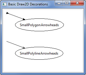
private void addSmallPolygonArrowheads(IFigure root) {
PolylineConnection conn = newFigureAndConnection(root,
"SmallPolygonArrowheads", 10, 10);
// Set the source decoration
PolygonDecoration decoration = new PolygonDecoration();
decoration.setTemplate(PolygonDecoration.INVERTED_TRIANGLE_TIP);
conn.setSourceDecoration(decoration);
// Set the target decoration
conn.setTargetDecoration(new PolygonDecoration());
}
private void addSmallPolylineArrowhead(IFigure root) {
PolylineConnection conn = newFigureAndConnection(root,
"SmallPolylineArrowheads", 10, 110);
// Set the target decoration
conn.setTargetDecoration(new PolylineDecoration());
}
6.3.2 Custom Decorations
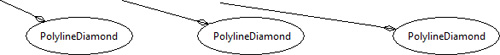
If arrowheads are not what you want, you can provide PointList to either PolylineDecoration or PolygonDecoration to render either a sequence of lines or a polygon at the connection end point (see Figure 6–11). The points you provide are relative to the origin, (0,0), which is the end of the connection, and use screen coordinates where the x-axis increases from left to right and the y-axis increases from top to bottom. The connection extends along the negative x-axis to the origin, so any points in the negative x-axis quadrants, such as (-1,1) and (-1,-1), will appear next to or on the connection line itself (see Figure 6–12 and Figure 6–13).
Figure 6–11. Detail showing connecton with a custom decoration.
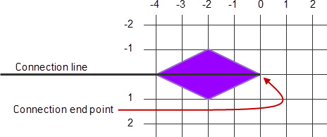
Figure 6–12. Connection line with a polygon diamond decoration.
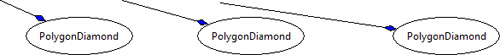
Figure 6–13. Connection line with a polyline diamond decoration.
PolylineConnection conn = newFigureAndConnection(
root, "PolygonDiamond", 230, 10);
PolygonDecoration decoration = new PolygonDecoration();
decoration.setBackgroundColor(ColorConstants.blue);
PointList points = new PointList();
points.addPoint(0, 0);
points.addPoint(-1, 1);
points.addPoint(-2, 0);
points.addPoint(-1, -1);
points.addPoint(0, 0);
decoration.setTemplate(points);
conn.setTargetDecoration(decoration);
PolylineConnection conn = newFigureAndConnection(
root, "PolylineDiamond", 230, 110);
PolylineDecoration decoration = new PolylineDecoration();
PointList points = new PointList();
points.addPoint(0, 0);
points.addPoint(-1, 1);
points.addPoint(-2, 0);
points.addPoint(-1, -1);
points.addPoint(0, 0);
decoration.setTemplate(points);
conn.setTargetDecoration(decoration);
For our GenealogyView, we want arrowheads slightly larger than the default arrowheads pointing from parent to marriage and from marriage to child. In addition, the arrowheads from parent to marriage should be dark gray and the arrowheads from marriage to child should be white. To accomplish this, add a new private static field to MarriageFigure and modify the addParent(...) and addChild(...) methods as shown below.
private static final PointList ARROWHEAD = new PointList(
new int[] { 0, 0, -2, 2, -2, 0, -2, -2, 0, 0 });
public PolylineConnection addParent(IFigure figure) {
PolylineConnection connection = new PolylineConnection();
connection.setSourceAnchor(new ChopboxAnchor(figure));
connection.setTargetAnchor(new MarriageAnchor(this));
PolygonDecoration decoration = new PolygonDecoration();
decoration.setTemplate(ARROWHEAD);
decoration.setBackgroundColor(ColorConstants.darkGray);
connection.setTargetDecoration(decoration);
return connection;
}
public PolylineConnection addChild(IFigure figure) {
PolylineConnection connection = new PolylineConnection();
connection.setSourceAnchor(new MarriageAnchor(this));
connection.setTargetAnchor(new ChopboxAnchor(figure));
PolygonDecoration decoration = new PolygonDecoration();
decoration.setTemplate(ARROWHEAD);
decoration.setBackgroundColor(ColorConstants.white);
connection.setTargetDecoration(decoration);
return connection;
}
Tip
Rather than constructing a PointList and repeatedly calling the addPoint(...) method, you can initialize the PointList by passing an array of integers as shown above. When instantiated with this constructor, every pair of integers in the array is taken as a point in the PointList.
Once these changes are made, the GenealogyView displays arrowheads at the end of its connections (see Figure 6–14).
Figure 6–14. Genealogy view showing arrowheads on each connection.
6.4 Routing Connections
Each connection has a connection router associated with it for determining the route the connection takes from the source anchor to the target anchor. Up to this point, all our connections have been using the default connection router, which connects source anchor with target anchor in a straight line. Draw2D provides a number of different connection router classes. The screenshots and code below are taken from the BasicRouters class (see Section 2.6 on page 20).
6.4.1 BendpointConnectionRouter
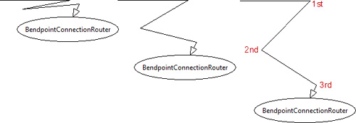
The BendpointConnectionRouter routes connections using a specified list of bendpoints (see Figure 6–15). Each bendpoint specifies a location on the canvas that can be an absolute canvas location, relative to the end points of the connection or some other developer-defined calculation. The figure and associated code below show a connection with three bendpoints. The first bendpoint is a fixed location on the canvas and does not change location as the figure is dragged around the canvas (see Section 6.4.1.2 on page 82). The second bendpoint is relative to both the first and third bendpoints, and the third bendpoint is relative to the ellipse (see Section 6.4.1.3 on page 82).
Figure 6–15. Bendpoint connection router examples.
PolylineConnection connection = newFigureAndConnection(...);
BendpointConnectionRouter router = new BendpointConnectionRouter();
AbsoluteBendpoint bp1 = new AbsoluteBendpoint(350, 10);
RelativeBendpoint bp2 = new RelativeBendpoint(connection);
bp2.setRelativeDimensions(new Dimension(-50, 20),
new Dimension(10, -40));
RelativeBendpoint bp3 = new RelativeBendpoint(connection);
bp3.setRelativeDimensions(new Dimension(0, 0),
new Dimension(20, -45));
bp3.setWeight(1);
router.setConstraint(connection,
Arrays.asList(new Bendpoint[] { bp1, bp2, bp3 }));
connection.setConnectionRouter(router);
6.4.1.1 Bendpoint Interface
The interface is used by BendpointConnectionRouter to query each bendpoint for its location. Draw2D provides two concrete bendpoint classes (see Section 6.4.1.2 and Section 6.4.1.3 below), and if they do not meet your needs, you can create your own bendpoint behavior by implementing this interface.
6.4.1.2 AbsoluteBendpoint
An AbsoluteBendpoint always returns a fixed location on the canvas. In our example above, the first bendpoint is an AbsoluteBendpoint instantiated with the coordinates 350, 10 and will always return that location.
AbsoluteBendpoint bp1 = new AbsoluteBendpoint(350, 10);
6.4.1.3 RelativeBendpoint
A RelativeBendpoint returns a location relative to the starting and ending points of the connection. Given an offset from the connection’s starting point, an offset from the connection’s ending point, and a weight, the bendpoint calculates a weighted location between the two offset locations.
More specifically, the bendpoint location (point B in Figure 6–16) is calculated by applying weights to points A and C.
Figure 6–16. Relative bendpoint calculation detail.
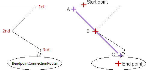
Bx = Ax * (1 – weight) + Cx * weight
By = Ay * (1 – weight) + Cy * weight
Locations A and C are determined by applying the offsets to the connection starting location and connection ending location respectively.
Ax = start point X + first offset X
Ay = start point Y + first offset Y
Cx = end point X + second offset X
Cy = end point Y + second offset Y
In our example code, the second bendpoint is defined as shown below:
RelativeBendpoint bp2 = new RelativeBendpoint(connection);
bp2.setRelativeDimensions(new Dimension(-50, 20),
new Dimension(10, -40));
In the code shown above, the first offset is -50, 20 and the second offset is 10, -40; therefore
Ax = start point X – 50
Ay = start point Y + 20
Cx = end point X + 10
Cy = end point Y – 40
A RelativeBendpoint weight ranges from 0 to 1 and shifts the bendpoint location closer to the connection start point (when 0 < weight < 0.5) or closer to the connection end point (when 0.5 < weight < 1). When the weight = 0, the bendpoint location is relative to the connection start point, and the connection end point is ignored. When the weight = 1, the bendpoint location is relative to the connection end point, and the connection start point is ignored. By default, the RelativeBendpoint weight is 0.5, so in this example
Weight = 0.5
thus
Bx = Ax/2 + Cx/2
By = Ay/2 + Cx/2
In our example code, the third bendpoint is defined as shown below:
RelativeBendpoint bp3 = new RelativeBendpoint(connection);
bp3.setRelativeDimensions(new Dimension(0, 0),
new Dimension(20, -45));
bp3.setWeight(1);
In this case the weight equals 1; thus the bendpoint location is offset from the connection end points and both the connection start point and the first offset are ignored.
Bx = end point X + 20
By = end point Y - 45
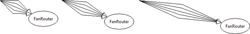
6.4.2 FanRouter
The FanRouter is useful for multiple connections between the same two anchors. When the FanRouter detects a connection that has the same starting anchor and ending anchor as a connection that already exists, it adds a bendpoint so that connections do not overlap (see Figure 6–17). It can be used in conjunction with other routers using the FanRouter’s setNextRouter(...) method as shown in the code below.
Figure 6–17. Fan router examples.
Ellipse ellipse = newFigure(container, "FanRouter", 60, 110);
PolylineConnection connection;
FanRouter router = new FanRouter();
router.setNextRouter(ConnectionRouter.NULL);
connection = newConnection(container, 10, 110, ellipse);
connection.setConnectionRouter(router);
ConnectionAnchor sourceAnchor = connection.getSourceAnchor();
ConnectionAnchor targetAnchor = connection.getTargetAnchor();
connection = newConnection(container, sourceAnchor, targetAnchor);
connection.setConnectionRouter(router);
connection = newConnection(container, sourceAnchor, targetAnchor);
connection.setConnectionRouter(router);
connection = newConnection(container, sourceAnchor, targetAnchor);
connection.setConnectionRouter(router);
connection = newConnection(container, sourceAnchor, targetAnchor);
connection.setConnectionRouter(router);
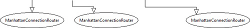
6.4.3 ManhattanConnectionRouter
The ManhattanConnectionRouter provides connections with an orthogonal route between the connection’s source and target anchors (see Figure 6–18).
Figure 6–18. Manhattan connection router examples.
PolylineConnection connection = newFigureAndConnection(...);
connection.setConnectionRouter(new ManhattanConnectionRouter());
6.4.4 NullConnectionRouter
If you do not specify one of the router types for a connection, then a NullConnectionRouter is used to route the connection from source anchor to target anchor in a straight line (see Figure 6–19). A single instance of this class is accessible via ConnectionRouter.NULL.
Figure 6–19. Null connection router examples.
![]()
PolylineConnection connection = newFigureAndConnection(...);
connection.setConnectionRouter(ConnectionRouter.NULL);
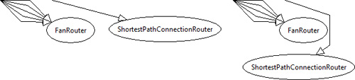
6.4.5 ShortestPathConnectionRouter
The ShortestPathConnectionRouter routes multiple connections around all of the figures in a container. As the various figures in a container are moved around, this router dynamically reroutes its connections so they do not intersect any figures in that container at any time (see Figure 6–20). This is the connection router we use in our GenealogyView example (see Section 7.1.2 on page 93).
The one big difference between this router and the previously mentioned routers is that the connections it manages must not be in the same container or “layer” (see Section 7.1 on page 91) as the figures it is observing. If a managed connection is in the same container, then as soon as the router adjusts any connection, it will think there is another change and try to adjust the connections again, in an infinite loop.
Figure 6–20. Shortest path connection router examples.
In the code below, an extra “layer” is added to contain the connection as discussed above. Normally this is not necessary in GEF-based diagrams because all connections are automatically added to a separate connection layer.
Ellipse ellipse = newFigure(container,
"ShortestPathConnectionRouter", 60, 210);
IFigure layer = new Figure() {
public boolean containsPoint(int x, int y) {
// Return false so mouse clicks flow to the next layer
return false;
}
};
container.getParent().add(layer);
PolylineConnection connection = newConnection(
layer, 100, 110, ellipse);
connection.setConnectionRouter(
new ShortestPathConnectionRouter(container));
6.5 Connection Labels
Connections can contain child figures, typically labels, to provide additional information about the connection. Typically, the connection layout is DelegatingLayout (see Section 5.3.2 on page 58) and the constraints are instances of BendpointLocator, ConnectionEndpointLocator, ConnectionLocator, and MidpointLocator.
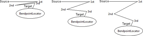
6.5.1 BendpointLocator
The BendpointLocator has no relation to the bendpoint class used as routing constraints; only the names are similar. BendpointLocator places a figure relative to a specific bend in the connection (see Figure 6–21). Each BendpointLocator has
• An index specifying next to which bendpoint the figure should be positioned
• A relative position indicating on which side of the bend (north, east, south, west, northeast, etc.) the figure should be positioned
• A gap indicating how close the figure should be positioned to the bend
Figure 6–21. Bendpoint locator examples.
connection.setLayoutManager(new DelegatingLayout());
Label label;
BendpointLocator locator;
label = new Label("source");
locator = new BendpointLocator(connection, 0);
locator.setRelativePosition(PositionConstants.WEST);
locator.setGap(5);
connection.add(label, locator);
label = new Label("1st");
locator = new BendpointLocator(connection, 1);
locator.setRelativePosition(PositionConstants.EAST);
locator.setGap(5);
connection.add(label, locator);
label = new Label("2nd");
locator = new BendpointLocator(connection, 2);
locator.setRelativePosition(PositionConstants.WEST);
locator.setGap(5);
connection.add(label, locator);
label = new Label("3rd");
locator = new BendpointLocator(connection, 3);
locator.setRelativePosition(PositionConstants.EAST);
locator.setGap(5);
connection.add(label, locator);
label = new Label("target");
locator = new BendpointLocator(connection, 4);
locator.setRelativePosition(PositionConstants.NORTH_WEST);
locator.setGap(5);
connection.add(label, locator);
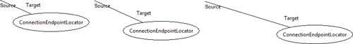
6.5.2 ConnectionEndpointLocator
ConnectionEndpointLocator positions figures relative to the source location or target location of a connection (see Figure 6–22). Additionally, you can specify “uDistance” and “vDistance.” uDistance is the distance between the connection’s owner and the figure being positioned, and vDistance is the distance between the connection and the figure being positioned. uDistance and vDistance default to 14 and 4 respectively.
Figure 6–22. Connection end point locator examples.
PolylineConnection connection = newFigureAndConnection(...);
connection.setLayoutManager(new DelegatingLayout());
Label label;
ConnectionEndpointLocator locator;
label = new Label("source");
locator = new ConnectionEndpointLocator(connection, false);
locator.setUDistance(2);
locator.setVDistance(5);
connection.add(label, locator);
label = new Label("target");
locator = new ConnectionEndpointLocator(connection, true);
connection.add(label, locator);
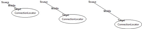
6.5.3 ConnectionLocator
ConnectionLocator positions figures at the source end, in the middle, or at the target end of a connection (see Figure 6–23).
Figure 6–23. Connection locator examples.
PolylineConnection connection = newFigureAndConnection(...);
connection.setLayoutManager(new DelegatingLayout());
Label label;
label = new Label("source");
connection.add(label,
new ConnectionLocator(connection, ConnectionLocator.SOURCE));
label = new Label("middle");
connection.add(label,
new ConnectionLocator(connection, ConnectionLocator.MIDDLE));
label = new Label("target");
connection.add(label,
new ConnectionLocator(connection, ConnectionLocator.TARGET));
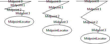
6.5.4 MidpointLocator
MidpointLocator positions figures at the midpoint of a specified segment within a connection (see Figure 6–24). Given a connection with n points from source to target, you must specify an integer between 0 and n – 1 indicating on which segment the figure is to be positioned.
Figure 6–24. Midpoint locator examples.
PolylineConnection connection = newFigureAndConnection(...);
connection.setLayoutManager(new DelegatingLayout());
for (int i = 0; i < 4; i++) {
Label label = new Label("midpoint " + i);
connection.add(label, new MidpointLocator(connection, i));
}
6.6 Summary
Draw2D provides a connection API that allows the user to connect figures to each other in a natural way. Connections have many configurable attributes such as their anchors, decorations, and routing algorithms.
References
Chapter source (see Section 2.6 on page 20).
GEF and Draw2D Plug-in Developer Guide, Eclipse Documentation (see http://help.eclipse.org/).
Hudson, Randy, Building Applications with Eclipse’s Graphical Editing Framework, EclipseCon 2004 presentation (see www.eclipsecon.org/2004/presentations.htm).
Moore, Bill, David Dean, Anna Gerber, Gunnar Wagenknecht, and Philippe Vanderheyden, Eclipse Development Using the Graphical Editing Framework and the Eclipse Modeling Framework. IBM Redbooks, February 2004.