
Chapter 2. A Simple Draw2D Example
Before covering the Draw2D infrastructure (see Chapter 3 on page 21) and each area of building a Draw2D diagram in depth, it is useful to create a simple example on which discussion can be based. This chapter takes a step-by-step approach to creating a simple Draw2D diagram representing the relationship between two people and their offspring. To start, we take an unsophisticated “brute force” approach, which we will refactor and refine in later chapters as we introduce more concepts. This process provides valuable firsthand experience using the Draw2D API.
2.1 Draw2D Installation
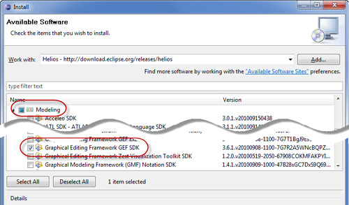
Select the Help > Install New Software... menu to install the GEF framework into Eclipse. When the Install wizard opens, select the Eclipse release update site (e.g., Indigo - http://download.eclipse.org/releases/indigo). Once the wizard refreshes, expand the Modeling category and select Graphical Editing Framework GEF SDK (see Figure 2–1). Alternatively, if you would like to install a different version of GEF, enter the GEF specific update site (http://download.eclipse.org/tools/gef/updates/releases) in the Install wizard and select the GEF features you wish to install. After you click Finish and restart Eclipse, the GEF framework installation is complete.
2.2 Draw2D Project
The full Eclipse RCP framework is not needed to use the Draw2D framework, so if you are creating a simple Java application, you can create a simple Java project in Eclipse and modify its build path to include the following Eclipse JAR files:
• ECLIPSE_HOME/plugins/org.eclipse.swt_3.7.X.vXXXX.jar
• ECLIPSE_HOME/plugins/org.eclipse.swt.win32.win32.x86_3.7.X.vXXXX.jar
• ECLIPSE_HOME/plugins/org.eclipse.draw2d_3.7.X.vXXXX.jar
Alternatively, if you are creating a diagram as part of a larger Eclipse RCP application, then create a Plug-in project with the following plug-in dependencies (see Chapter 2 in the Eclipse Plug-ins book for more about Plug-in projects):
• org.eclipse.ui
• org.eclipse.core.runtime
• org.eclipse.draw2d
Since the second half of this book describes techniques that require the Eclipse RCP framework, we use a Plug-in project rather than a simple Java project for all of the samples in this book.
2.3 Draw2D Application
Since the full Eclipse RCP framework is not needed to use the Draw2D framework, we create a simple Java class containing a main(...) method.
package com.qualityeclipse.genealogy.view;
import org.eclipse.draw2d.*;
import org.eclipse.draw2d.geometry.*;
import org.eclipse.swt.SWT;
import org.eclipse.swt.layout.GridData;
import org.eclipse.swt.layout.GridLayout;
import org.eclipse.swt.widgets.Canvas;
import org.eclipse.swt.widgets.Composite;
import org.eclipse.swt.widgets.Display;
import org.eclipse.swt.widgets.Shell;
public class GenealogyView
{
public static void main(String[] args) {
new GenealogyView().run();
}
}
Tip
All of this source can be downloaded from www.qualityeclipse.com.
The main(...) method calls a run() method to initialize the shell, create the diagram, and show the shell. The run() method is not interesting with respect to Draw2D and is included here only for completeness. For more information on SWT and shells, please see the Eclipse Plug-ins book.
private void run() {
Shell shell = new Shell(new Display());
shell.setSize(365, 280);
shell.setText("Genealogy");
shell.setLayout(new GridLayout());
Canvas canvas = createDiagram(shell);
canvas.setLayoutData(new GridData(GridData.FILL_BOTH));
Display display = shell.getDisplay();
shell.open();
while (!shell.isDisposed()) {
while (!display.readAndDispatch()) {
display.sleep();
}
}
}
The run() method calls the createDiagram(...) method to create and populate the diagram. This method creates a root figure to contain all of the other figures in the diagram (see Chapter 4 on page 27 for more about figures). A simple layout manager (see Chapter 5 on page 55 for more about lay out managers) is used to statically lay out the figures that are added later in this section. Finally, the last bit of code creates a Canvas on which the diagram is displayed and a LightweightSystem used to display the diagram (see Section 3.1 on page 21 for more about LightweightSystem).
private Canvas createDiagram(Composite parent) {
// Create a root figure and simple layout to contain
// all other figures
Figure root = new Figure();
root.setFont(parent.getFont());
XYLayout layout = new XYLayout();
root.setLayoutManager(layout);
// Create a canvas to display the root figure
Canvas canvas = new Canvas(parent, SWT.DOUBLE_BUFFERED);
canvas.setBackground(ColorConstants.white);
LightweightSystem lws = new LightweightSystem(canvas);
lws.setContents(root);
return canvas;
}
Tip
Always set the font for the root figure
root.setFont(parent.getFont());
so that each Label’s preferred size will be correctly calculated.
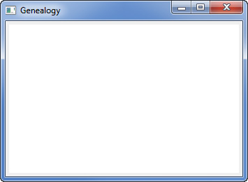
If you run the main(...) method, an empty window will appear (see Figure 2–2).
Figure 2–2. Empty Genealogy window.
Next, we want to add figures to the diagram representing a man, a woman, and their one child. Add the following to the createDiagram(...) method so that these figures are created and displayed.
private Canvas createDiagram(Composite parent) {
... existing code here ...
// Add the father "Andy"
IFigure andy = createPersonFigure("Andy");
root.add(andy);
layout.setConstraint(andy,
new Rectangle(new Point(10, 10), andy.getPreferredSize()));
// Add the mother "Betty"
IFigure betty = createPersonFigure("Betty");
root.add(betty);
layout.setConstraint(betty,
new Rectangle(new Point(230, 10), betty.getPreferredSize()));
// Add the son "Carl"
IFigure carl = createPersonFigure("Carl");
root.add(carl);
layout.setConstraint(carl,
new Rectangle(new Point(120, 120), carl.getPreferredSize()));
... existing code here ...
}
Tip
Rather than adding the figure and then separately setting the layout constraint:
root.add(andy);
layout.setConstraint(andy,
new Rectangle(new Point(10, 10),
andy.getPreferredSize()));
combine this into a single statement using the IFigure.add(child, constraint) method:
root.add(andy,
new Rectangle(new Point(10, 10),
andy.getPreferredSize()));
Refactor the createDiagram(...) method above to use this more compact form, and inline the layout as we do not need to refer to it.
root.setLayoutManager(new XYLayout());
The createDiagram(...) method now calls a new createPersonFigure(...) method to do the work of instantiating and initializing the figure representing a person. This person figure contains a nested Label figure to display the person’s name (see Section 4.3.2 on page 35 for more on nested figures).
private IFigure createPersonFigure(String name) {
RectangleFigure rectangleFigure = new RectangleFigure();
rectangleFigure.setBackgroundColor(ColorConstants.lightGray);
rectangleFigure.setLayoutManager(new ToolbarLayout());
rectangleFigure.setPreferredSize(100, 100);
rectangleFigure.add(new Label(name));
return rectangleFigure;
}
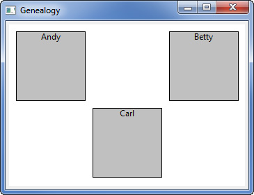
Now, when the main(...) method is run, the following window appears (see Figure 2–3).
Figure 2–3. Genealogy window with three people.
Next, add more code to the createDiagram(...) method to create a “marriage” figure representing the relationship among the three people. This additional code calls a new createMarriageFigure(...) method to instantiate and initialize the marriage figure. This marriage figure is displayed using a PolygonShape (see Section 4.2 on page 29 for more about shapes) in the form of a diamond.
private Canvas createDiagram(Composite parent) {
... existing figure creation for people here ...
IFigure marriage = createMarriageFigure();
root.add(marriage,
new Rectangle(new Point(145, 35),
marriage.getPreferredSize()));
... prior code here ...
}
private IFigure createMarriageFigure() {
Rectangle r = new Rectangle(0, 0, 50, 50);
PolygonShape polygonShape = new PolygonShape();
polygonShape.setStart(r.getTop());
polygonShape.addPoint(r.getTop());
polygonShape.addPoint(r.getLeft());
polygonShape.addPoint(r.getBottom());
polygonShape.addPoint(r.getRight());
polygonShape.addPoint(r.getTop());
polygonShape.setEnd(r.getTop());
polygonShape.setFill(true);
polygonShape.setBackgroundColor(ColorConstants.lightGray);
polygonShape.setPreferredSize(r.getSize());
return polygonShape;
}
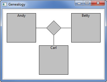
Now the marriage figure is displayed when the main(...) method is run (see Figure 2–4).
Figure 2–4. Genealogy window showing marriage figure.

Finally, connect each of the people to the marriage (see Figure 2–5), showing their relationship to one another by modifying the createDiagram(...) method again. This is accomplished by calling a connect(...) method to create the line connecting the center of one figure to the center of another (see Chapter 6 on page 69 for more about connections).
private Canvas createDiagram(Composite parent) {
... existing figure creation for marriage here ...
root.add(connect(andy, marriage));
root.add(connect(betty, marriage));
root.add(connect(carl, marriage));
... prior code here ...
}
private Connection connect(IFigure figure1, IFigure figure2) {
PolylineConnection connection = new PolylineConnection();
connection.setSourceAnchor(new ChopboxAnchor(figure1));
connection.setTargetAnchor(new ChopboxAnchor(figure2));
return connection;
}
Figure 2–5. Genealogy window showing connections.
2.4 Draw2D View
The above example diagram can also be displayed in a view that is part of an Eclipse RCP application (see Chapter 7 in the Eclipse Plug-ins book for more about views). Start by adding the following extension to the plugin.xml:
<extension point="org.eclipse.ui.views">
<category
id="com.qualityeclipse.gef"
name="GEF Book">
</category>
<view
category="com.qualityeclipse.gef"
class="com.qualityeclipse.genealogy.view.GenealogyView"
id="com.qualityeclipse.genealogy.view"
name="Genealogy"
restorable="true">
</view>
</extension>
Now modify the GenealogyView class to be a subclass of org.eclipse.ui.part.ViewPart, and add the following methods:
package com.qualityeclipse.genealogy.view;
... existing imports ...
import org.eclipse.ui.part.ViewPart;
public class GenealogyView extends ViewPart
{
public void createPartControl(Composite parent) {
createDiagram(parent);
}
public void setFocus() {
}
... existing methods ...
}
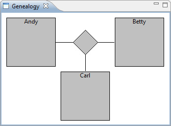
When you launch the runtime workbench and open the Genealogy view, you’ll see something like this (see Figure 2–6).
Figure 2–6. The Genealogy view.
Tip
When developing a Draw2D view with figures that don’t have dependencies on the Eclipse RCP framework, add a main(...) method to your ViewPart as shown in Section 2.3 on page 9 so that you can quickly test your diagram in a shell rather than launching the entire Eclipse RCP application.
2.5 Draw2D Events
We would like the user to be able to drag the figures around the diagram. To accomplish this, we create a new Draw2D event listener to process mouse events, move figures, and update the diagram. Start by creating a new FigureMover class that implements the Draw2D MouseListener and MouseMotionListener interfaces. Add a constructor that hooks the listener to the specified figure and a concrete method that does nothing for each method specified in the interfaces.
package com.qualityeclipse.genealogy.listener;
import org.eclipse.draw2d.*;
import org.eclipse.draw2d.geometry.*;
public class FigureMover
implements MouseListener, MouseMotionListener
{
private final IFigure figure;
public FigureMover(IFigure figure) {
this.figure = figure;
figure.addMouseListener(this);
figure.addMouseMotionListener(this);
}
... stub methods here ...
}
When the user presses the mouse button, we need to record the location where the mouse down occurred by adding a field and implementing the mousePressed(...) method. In addition, this method must mark the event as “consumed” so that the Draw2D event dispatcher will send all mouse events to this listener’s figure until the mouse button is released.
private Point location;
public void mousePressed(MouseEvent event) {
location = event.getLocation();
event.consume();
}
As the user moves the mouse around with the mouse button held down, we need to move the figure in the same direction and distance. The mouseDragged(...) method calculates the distance moved, moves the figure, and marks the event as consumed. To move the figure, we must update both the figure’s bounding box and the layout information. Both the figure’s original location and new location must be marked as “dirty” so that the update manager will redraw the diagram appropriately. The getBounds() method returns the actual rectangle object used by the figure to remember its bounds, so we cannot modify that object. Instead, we call getCopy() before calling translate(...) to prevent any undesired side effects.
public void mouseDragged(MouseEvent event) {
if (location == null)
return;
Point newLocation = event.getLocation();
if (newLocation == null)
return;
Dimension offset = newLocation.getDifference(location);
if (offset.width == 0 && offset.height == 0)
return;
location = newLocation;
UpdateManager updateMgr = figure.getUpdateManager();
LayoutManager layoutMgr = figure.getParent().getLayoutManager();
Rectangle bounds = figure.getBounds();
updateMgr.addDirtyRegion(figure.getParent(), bounds);
bounds = bounds.getCopy().translate(offset.width, offset.height);
layoutMgr.setConstraint(figure, bounds);
figure.translate(offset.width, offset.height);
updateMgr.addDirtyRegion(figure.getParent(), bounds);
event.consume();
}
Tip
To prevent undesired side effects, call getCopy(), then modify the copy rather than modifying the original rectangle.
When the mouse button is released, we clear the cached location and mark the event as consumed.
public void mouseReleased(MouseEvent event) {
if (location == null)
return;
location = null;
event.consume();
}
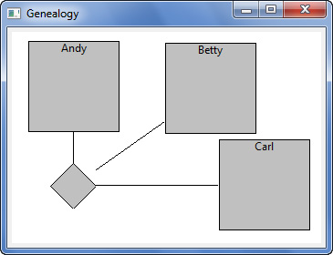
Finally, modify the GenealogyView class to import the FigureMover class and hook the listeners to each person figure and the marriage figure by modifying the createPerson(...) and createMarriage() methods. Once these steps are complete, the figures can be dragged around the window (see Figure 2–7). For more information on how the framework determines where figures are for the mouse events, see Chapter 7 on page 91.
private RectangleFigure createPersonFigure(String name) {
... existing code here ...
new FigureMover(rectangleFigure);
return rectangleFigure;
}
private PolygonShape createMarriageFigure() {
... existing code here ...
new FigureMover(polygonShape);
return polygonShape;
}
Figure 2–7. Genealogy view showing dragging of figures.
Implementing listeners such as these is useful when providing user interaction with pure Draw2D diagrams, but much of this functionality, such as dragging figures around a diagram, is already provided by the higher-level GEF framework.
2.6 Book Samples
Source code for each chapter can be downloaded and compiled into Eclipse for the reader to review, run, and modify. Go to www.qualityeclipse.com and click Book Samples, or go directly to the Quality Eclipse update site www.qualityeclipse.com/update to download the QualityEclipse Book Samples view into Eclipse. Once the samples are installed, open the view by selecting Eclipse > QualityEclipse Book Samples.
The view can be used to download the content for each chapter and compare the workspace content to the content in each chapter.
2.7 Summary
This chapter quickly brought the reader through a simple Draw2D example which includes a few figures that can be dragged and dropped on the canvas. The following chapters will walk through Draw2D content in more detail. All source code covered in this book can be downloaded from www.qualityeclipse.com.
References
Chapter source (see Section 2.6 on page 20).
Clayberg, Eric, and Dan Rubel, Eclipse Plug-ins, Third Edition. Addison-Wesley, Boston, 2009.
GEF and Draw2D Plug-in Developer Guide, Eclipse Documentation (see http://help.eclipse.org/).
Lee, Daniel, Display a UML Diagram using Draw2D, August 2005 (see www.eclipse.org/articles).