
Mirrors
A. Fernández-García*; F. Sutter†; J. Fernández-Reche*; E. Lüpfert† * CIEMAT-PSA, Almería, Spain
† German Aerospace Center (DLR), Cologne, Germany
Abstract
One of the main principles of concentrated solar power (CSP) technologies is based on large mirror or reflector surfaces, which reflect the incoming radiation onto a focus. The largest component of a CSP system is the mirror. Therefore, the feasibility of these technologies strongly depends on the reflector material used to obtain a suitable mirror. A very relevant issue is to find a cost-effective mirror with appropriate optical and geometrical properties, which is able to resist the environmental stress. The key optical property in a solar mirror is the solar specular reflectance. The quality of the concentrated solar flux profile on the focus is directly related to the accuracy achieved by the mirror to conform the desired concentrator geometry. Accelerated conditions are used in climate chambers when predicting a mirror's durability, to save time and costs. These results are combined with outdoor tests results to obtain realistic acceleration factors. In addition, the cleaning method must be optimized to reduce the operation and maintenance (O&M) costs.
Keywords
Solar mirror; Reflectance; Shape; Durability; Cleaning
3.1 Introduction
The solar mirror (also called solar reflector) is the first key component in the energy conversion process; any solar radiation that is not reflected by it in the direction of the receiver implies a loss of system efficiency. In addition, this component represents a crucial aspect in the construction and further operation of a concentrated solar power (CSP) plant because it involves a significantly large surface area (e.g., the reflective surface in a parabolic-trough collector (PTC) plant is 0.58–1.02 ha per MWe produced [1]). As a consequence, the feasibility strongly depends on the material and manufacturing process used to achieve a suitable solar concentrator. A concentrator is defined as a reflector with the proper shape.
In general, concentrators for CSP applications must meet the following set of requirements:
• Appropriate optical properties: reflectors must have high specular reflectance in the whole solar radiation spectrum.
• Suitable concentrator geometry: the concentrator shape should be as similar to the ideal geometry as possible, to ensure the highest possible amount of the solar radiation is reflected onto the absorber.
• Cost-effective reflector material: although some years ago the reflectors represented ~21% of solar field material cost [2], recently this share has been reduced to 10%–20%. Consequently, mirror panels have become a competitive component in the market, with a cost of 11–15€/m2, depending on thickness and shape.
• Reflector material able to resist the environmental conditions (temperature, radiation, wind load, dust, rain, corrosive atmospheres, etc.), as well as the mirror cleaning procedures, along its lifetime.
• Minimized maintenance required to avoid or remove the soiling deposited on the reflector surfaces by an optimized cleaning strategy.
The materials roadmap published by the European Commission specified that solar reflectors for CSP must comply with several requirements regarding their optical performance, durability, cost, sustainability, etc. The target performance for silvered reflectors in the following decade (2020–30) is set at 95%–96%, considering a reference starting point of 94% in 2010 [3]. It is also projected that the reflector performance will be maintained at appropriate levels during its lifetime, which is expected to be 10–30 years under the relevant outdoor environments [4] or even more than 30 years [5].
This chapter includes a description of solar mirrors for concentrating solar applications, their fundamentals, types, specifications, measurement and assessment of performance parameters, and future trends expected in the coming years.
3.2 Fundamentals of concentrating optics and processes in solar mirrors
Reflector materials for concentrating solar systems must be highly specular in the whole solar spectrum. Also, the accuracy of the reflector shape to conform the desired concentrator geometry must be good enough to assure the quality of the concentrated solar flux profile on the focus. In order to define these concepts clearly, basic definitions related to mirror optics are included.
3.2.1 Interaction between radiation and mirror
When radiation interacts with matter (in this case, specifically a mirror), the following phenomena may occur: a part of the radiation can be reflected, a part can be absorbed, and, in the case of transparent materials, a part can be transmitted. The material properties associated with these behaviors are the absorptance, α, the reflectance, ρ, and the transmittance, τ, respectively (see Fig. 3.1).

These dimensionless parameters (ranging from 0 to 1) depend on the wavelength, λ, and the direction, θi, of the incident radiation, the surface temperature, Ts, and the material properties. In the case of ρ, it also depends on the direction of the reflected radiation, θr. According to the first law of thermodynamics [6], the relationship among these is stated by Eq. (3.1):
For an opaque body (with no radiation transmitted through it), the transmittance is considered to be zero. According to the National Bureau of Standards, the ending -ivity involves an intensive property, i.e., an intrinsic material property, e.g., resistivity, thermal conductivity, etc. The ending -ance refers to extensive properties of materials, e.g., strength or electrical conductance. As a consequence, when talking about optical properties of materials used in solar applications (reflectance, transmittance, and absorptance) the ending -ance must be used, because such materials can be degraded by the thermal processes, soiling, mechanical damage, corrosion, etc., which affect the intrinsic properties of such materials [7]. In particular, this chapter focuses on the reflectance parameter, as this quantifies the performance and quality of a mirror.
3.2.2 Reflectance definitions
The reflectance is a parameter used for quantifying the ability of bodies, materials, or surfaces to reflect the radiation reaching them. According to the standard EN ISO 9488 [8], reflectance is defined as the ratio of the radiant flux reflected from a surface, Φr, to that of the incident radiation flux, Φi (see Eq. 3.2).
The reflectance is written with the influencing parameters (λ, θi, θr, and Ts) in brackets, ρ(λ, θi, θr, Ts). ρ also depends on the light polarization (polarization can be neglected only at near-normal incidence). Sunlight is not polarized; thus, for solar concentrating applications, the unpolarized reflectance is considered, given by the average value of s and p polarized reflectance values [6]. In the following, polarization will be omitted, and “reflectance” refers to “unpolarized reflectance.”
Solar radiation follows the laws of reflection [9]. According to the first law of reflection, the incident beam, the reflected beam, and the surface normal at the point of incidence are in the same plane. The second law of reflection states that the reflected beam is at the same angle away from the surface normal, θr, as the incident beam, θi (see Fig. 3.1). Thus θi=θr=θ.
Different types of reflectance can be defined respecting the direction of the reflection (specular, diffuse, or hemispherical reflectance) or to λ (spectral or solar-weighted reflectance). The subsections above include the definitions of these parameters. Nomenclature used is according to standards set in Refs. [7,8].
While the amount of reflected radiation is a property of materials, its angular distribution is related with the microscopic flatness or roughness surface of the material. The following reflectance cases can be defined, depending on the direction of the reflection.
3.2.2.1 Specular reflectance
The specular reflectance is defined as the ratio of the energy flux reflected by a surface in the specular direction to the radiation incident on it [7]. It describes the case of reflection on a perfectly flat or planar surface (i.e., with roughness much less than the radiation wavelength, for instance, highly polished), where parallel incident beams are reflected as parallel beams, according to the laws of reflection [10] (see Fig. 3.2 left).

Although this is the ideal case, reflection at real surfaces is always mixed with a certain amount of scattering [11,12]. For highly specular surfaces, this scattering is close to the specular direction. The specular reflectance is written as ρ(λ, θi, θr, φ, Ts) (where θr can be omitted) and depends on the acceptance angle, φ, which is the angle associated to the detector aperture of the measurement instrument. In this text, φ means the half acceptance angle. This parameter is also defined as the angle between the specular direction and the direction of the admissible dispersion on the surface for the specific application [7].
Strictly speaking, the ideal specular reflectance is related to φ=0, whereas the measurement at any small offset φ is more appropriately termed near specular reflectance [10]. To simplify, near specular reflectance is typically known as specular reflectance. If a specular surface element irradiated by an incident beam is viewed, the element appears brighter from the specular viewing direction—that is, the mirror-like effect is produced.
In solar thermal concentrating applications, only the solar radiation reflected by the concentrator in the specular direction with a certain φ reaches the receiver and is converted in thermal energy. As a consequence, the specular reflectance is the representative parameter of a solar reflector.
3.2.2.2 Diffuse reflectance
When a set of parallel beams impacts on a body with a rough or microscopically structured surface of a size equal or greater than the λ of the incident radiation, each individual beam meets a different surface slope and the law of reflection takes effect for a different θr to the surface normal at the contact point (see Fig. 3.3).

As a result, the radiation is diffusely scattered in all directions in the plane of incidence (see Fig. 3.2 center). If a diffuse surface element irradiated by an incident beam is viewed, the element appears equally bright from all viewing directions. The amount of diffuse scattering depends on the level of roughness or microscopic surface structuring. The ideal diffuse reflector is a Lambertian surface, where an equal amount of radiation is scattered in each direction of the hemisphere. The goal in reflector materials for concentrating solar applications is that the surface structure is flat enough to minimize the scattering. Real surfaces are not only specular or diffuse, but generally have an intermediate behavior, as indicated in Fig. 3.2 right.
3.2.2.3 Hemispherical reflectance
The hemispherical reflectance is the ratio of the energy flux reflected by a surface within the complete hemisphere over that surface to the radiation incident on it [7]. Therefore, it comprises the total amount of reflected intensity (both specular and diffuse reflection) over the entire hemisphere. The hemispherical reflectance is written as ρ(λ, θi, h, Ts). In the hemispherical reflectance the angle θr is substituted by “h,” which means hemispherical.
3.2.2.4 Specularity
The term specularity describes the beam spread caused by scattering and is defined as the ratio between specular and hemispherical reflectance. A surface with perfect specularity produces no scattering. In that case, specular and hemispherical reflectance values are the same and the specularity is equal to the unit.
3.2.2.5 Spectral reflectance
The spectral reflectance is the reflectance measured at a given Ts and λ, within a small wavelength interval, Δλ, centered at λ [7]. Spectral reflectance is typically named monochromatic reflectance and may be specular, diffuse, or hemispherical. This parameter is indicated with the subscript “λ” after the ρ symbol. Consequently, ρλ(λ, θi, θr, φ, Ts) is the spectral specular reflectance and ρλ(λ, θi, h, Ts) is the spectral hemispherical reflectance. A graph representing the specular reflectance over a λ range is called a reflectance spectrum.
3.2.2.6 Solar reflectance
The solar (also called solar-weighted) reflectance is a weighted average of the spectral reflectance over the solar λ range, with a standard solar spectral irradiance distribution as the weighting function. To express that a value is the solar-weighted reflectance, a subscript “s” is included after the ρ symbol. Accordingly, ρs([λa, λb], θi, θr, φ, Ts) is the solar specular reflectance and ρs([λa, λb], θi, h, Ts) is the solar hemispherical reflectance. In this nomenclature, λa and λb are the lower and upper limits of the λ range for the evaluation. According to the standards ASTM E903-82 [13] and ISO 9050 [14], solar weighting is calculated as in Eq. (3.3):

where Gb(λ) is the direct solar irradiance. It is recommended to use the direct solar irradiance spectrum ASTM G173-03 [15] for direct irradiance and the appropriate Air Mass (i.e., for Europe and United States it is AM 1.5) [7]. If another solar irradiance spectrum is used, it must be indicated when expressing the solar reflectance to avoid confusion in the interpretation of the results. Fig. 3.4 shows both a typical hemispherical reflectance spectrum of a silvered second-surface mirror and the solar irradiance spectrum from ASTM G173-03 [15], plotted in the same λ range.

Concerning the proper wavelength range, the following recommendations are included in Ref. [10]:
• The λ range of the solar spectral irradiance provided in Ref. [15] is λ=[280, 4000] nm. However, as the near-infrared range has low impact, it is practically appropriate to evaluate the range λ=[280, 2500] nm, using standard laboratory equipment.
• Some instruments require the use of an extra ultraviolet (UV)-lamp to measure from 280 nm. Therefore, the starting range of the measurement can be changed to 300 nm. This is allowed since the UV tail has low impact on the final average value.
• The wavelength interval of the measurement shall be the maximum of 5 nm.
According to Ref. [7], unless otherwise specified, Ts taken into consideration is the ambient temperature (25°C). Consequently, in the rest of this work, Ts is omitted from the nomenclature except when it is different from 25°C.
3.2.3 Geometry definitions
The shape of the reflector determines the ability of the mirror to geometrically focus the incoming sunrays towards the receiver of the concentrating solar system. The ideal shape for focusing parallel light is achieved with parabolic sections. So-called point-focus systems typically require two-axis curving, while linear-focus systems work with one-axis curving (cylindrical, trough-like). Depending on the concentrator system layout, the curvature is not necessarily specified as a parabola. Special mirror shapes with complex geometry are used for systems with secondary reflectors.
The entire mirror shape is described at each location of the reflecting area by its position and orientation, in mathematical terms usually by the normal vector representing a small piece of reflector area. The surface normal vector of a reflector can be used to calculate the reflection according to Snell's law, which describes the direction of the reflected ray in the same angle from the normal vector in a plane determined by the ray and the normal vector. Deviation of the reflector shape (also defined as “local” slope deviation) provokes a deviation of the reflected ray by twice the slope deviation angle of the respective mirror area element.
For this reason, parameters to evaluate the mirror shape quality or measure deviations in actual, ideal, or design surface are the best statistics to evaluate the shape quality of solar reflectors. This slope deviation can be evaluated locally over the complete reflector surface (sdx) and statistically to determine the mean value (SDxmean), the standard deviation (SDxstd), and the mostly used root mean square (SDxrms, or just SDx) of local slope deviation values (Eqs. 3.4–3.7), describing these parameters with their components in x direction of the collector coordinate system, and SDy, etc., respectively, for the y direction:


While mean values indicate the average of the angle deviation in the orientation of the reflection surface, standard deviation is a measurement of the dispersion of these deviations, and root mean square gives the total deviation of the reflecting surface combining both influences [16].
In general, local slope deviation values can be approximated with the normal distribution. However, contiguous points of the reflecting surface are highly correlated. That means, from a geometrical point of view, that the mirror surface is a continuous 3D curve so that height and thus slope deviations are continuous too.
For line-focusing systems, the performance is mainly determined by slope deviation in curved direction (SDx), while for point-focusing systems (heliostats and parabolic dishes), both x and y direction are of equal relevance.
The performance is often evaluated in terms of the quality of the concentrated beams in the focal region. Some other parameters can be defined to take into account the receiver position and size [17]. The intercept factor (see Section 5.2) is defined by the fraction of rays hitting the receiver in relation to all reflected rays, thus valuating the size of the receiver. The standard focus deviation or simply focus deviation, FD, is the root mean square of the calculated deviation of reflected rays from its design target, accordingly taking into account the effect of distance between mirror and receiver better than the slope deviation parameters. Such parameters, which are directly derived from those defined here, are often best suited for mirror evaluation for specific standard geometries, in particular for parabolic-trough mirror panels (see Chapter 5 (Section 5.2.1.1)).
In line-focusing systems, FDx is the transversal focus deviation parameter, quantifying the width of the resulting focus distribution. Ray-tracing analyses on measurement data from parabolic-trough mirrors of different manufacturing qualities have shown that the focus deviation FDx and the energy efficiency (measured as intercept factor) of a PTC are closely related to each other. Fig. 3.5 shows this relation for a “degraded sun” of 5.7 mrad. The “degraded sun” takes into account typical additional optical errors of the concentrating collector and thus gives a realistic estimate of the expected intercept factor of a collector equipped with these mirrors. The graph includes mirrors of different manufacturers and bending technologies and thus also different patterns of shape characteristics. All mirrors are RP3 type, which is a parabolic-trough mirror with the dimensions 1700×1641×4 mm3 and 1700×1501×4 mm3 for inner and outer mirror, respectively, and a focal length of 1710 mm.

The graph with the arbitrary fit line shows the consistency of the mirror quality parameter FDx with the intercept factor and thus overall optical efficiency of a PTC equipped with these mirrors of different manufacturing processes. For combining the intercept factor values of inner and outer mirror panels, the weighting of the mirror aperture area for RP3 panels of 56% and 44%, respectively, is taken into account. The specification of the standard FD can replace previously used standard slope deviations and definitions related to laser-beam intercept factors on the receiver size without the direct need to change measurement procedures but with much higher significance as a quality parameter for a key element of CSP technology. The minimum specification of RP3 mirror panels (f=1710 mm) should fulfill FDx of below 12 mm. FDx values of below 10 mm are considered good and values below 8 mm very good. The current state of the art for the FD in mirror production is below 8 mm, with relevant impact on the solar field performance. A surface area of at least 98% of the mirror aperture area should be evaluated [18].
Geometrical measurements of mirror panels also include outer dimensions, and accuracy of location and angle of the mirror mounting elements (ceramic pads).
3.3 Materials and configurations
Concentrating solar collectors require the use of reflecting surfaces with highly specular reflectance in the solar spectrum. Reflective metals typically used in solar reflectors are silver and aluminum, due to their reflective properties in the spectral range of sunlight on earth. Fig. 3.6 shows the hemispherical reflectance spectra of these two pure metals [19] and the direct solar irradiance spectrum from [15].

As Fig. 3.6 shows, silver reflectance is considerably higher than aluminum in some wavelength ranges. Aluminum has an absorption band around 800 nm, which is the main reason to have a higher solar-weighted reflectance when the whole solar spectrum is considered (see Section 3.2.2). The solar hemispherical reflectance of silver surfaces may reach in vacuum max. 0.98, while for aluminium the maximum is 0.92. In technical mirrors, even when using extremely thin (<0.1 mm) low-iron glass as front cover, the reflectance is at least 1% less [75].
It is worth mentioning an important detail concerning the comparison of these two reflectance spectra. Although the silver spectrum is higher than the aluminum one in almost all the wavelength range, in the UV range the contrary behavior is observed. Therefore, in applications where UV radiation is needed (e.g., water treatment), aluminum reflectors may be advantageous [20].
Solar reflector configurations are usually highly shining metals or metal coatings on suitable substrates such as glass, polymers, or metals. With opaque substrates, the reflective layer must always be front-surfaced, for example, polished aluminum. In this case, the reflector is known as a “first-surface” or “front-surface” reflector. If a transparent substrate (glass, methacrylate, polycarbonate) is used, the coating may be on the back surface, being a “second-surface” reflector. Both metals require high-quality protective coating as protection from corrosion (oxidation). Front surface mirrors require transparent top coatings while second-surface mirrors are always back-protected with coatings (varnish) or bonded to a further substrate. Mirror systems consisting of thin coatings with specific refractive index gradients have been analyzed under lab conditions, but have not become state of the art, mainly due to their undesired dependency of the incident angle. In the following subsections, these material configurations are described.
3.3.1 Second-surface mirrors
Solar mirrors are classified as second surface when the reflective layer is deposited on the back of a transparent substrate, typically glass. In this kind of reflectors, solar beams have to go through the transparent top layer before impinging on the reflective layer. Depending on the glass layer, they are categorized as follows.
3.3.1.1 Silvered thick-glass mirrors
The most widespread type of reflectors is the monolithic-glass-based one. In general, it is composed by a reflecting silver layer coated with a glass layer on the front side. Although there is no strict classification between thick and thin glass reflectors, the distinction level is considered at a glass-layer thickness of about 1 mm [21]. The glass thickness for thick-glass reflector typically is 3 or 4 mm. It is well known that glass may absorb little of the solar energy spectrum if its Fe2O3 content is low (Fe2O3 content around 0.02%) [22]. The type of glass for solar applications is called “clear white,” or low-iron glass.
The silver layer (with a typical density of between 0.8 and 1.2 g/m2 [2]) is extremely vulnerable to ambient contaminants, moisture, or salty atmospheres. Thus, although in this configuration silver is properly protected on the front side by the glass layer, the silver must be conveniently protected also on the back side. This protection is usually achieved by a copper layer and two or three protective paints, as shown in Fig. 3.7.

These mirrors are manufactured following the conventional wet chemistry process: the clean glass is sensitized with SnCl2, the Ag layer is applied by chemical reductive processes, the Cu layer is applied by chemical processes, the mirror-backing paint is applied by various techniques, and the applied paint is force cured by heating [23]. The copper layer has a significant protective role to retard tarnishing of the silver layer and provides a surface for the mirror paint to adhere to [21].
To obtain more environmentally friendly mirrors, the copper layer should be avoided (i.e., substituting it with a cation-ion based solution [21,23]) and the back paints should reduce the lead content. Currently, the lead content of back protective paints vary between 0.5% and 2.5% by weight [21] and the goal is to achieve lead-free paints, with <0.15% lead by weight [2].
In the manufacturing process of a curved thick-glass mirror, the flat glass panel is heated on precise parabolic molds in ovens to achieve the parabolic shape; the glass is then silvered on the back and covered with the back coatings (see Fig. 3.8 left). Finally, ceramic pads used for mounting the mirrors to the collector structure are attached with a special adhesive [24]. When reflectors are used for solar tower heliostats, they are manufactured flat and are cold-conformed in a process called canting (see Fig. 3.8 right). Therefore, due to the increased cost of the manufacturing process, mirrors for PTC are more expensive than those for heliostats. In both cases, recent market developments have promoted a significant cost reduction.

Concerning reflectance properties, high reflectance is obtained due to the silver intrinsic behavior (see Fig. 3.6) and small scattering can be expected because glass is a highly smooth substrate. The version of these reflectors with copper layer and paints with a high lead content has demonstrated excellent durability [24]. However, new reflectors without lead and copper as corrosion inhibitors still have to prove their durability.
The maximum tensile strength of the glass mirrors depends on their thermal treatment (annealing, hardening) in the production process. Depending on the cooling speed, the resistance to mechanical breakage and the size of the fragments may vary significantly, having an impact on breakage mechanisms with the highest wind-loads and handling safety.
3.3.1.2 Silvered thin-glass mirrors
The composition of silvered thin-glass reflectors is basically the same as the previous one. The only difference lies in the glass thickness, in this case, less than around 1 mm. To obtain the concentrator shape, reflectors are bonded to metal, composite, or glass back structures. These mirrors have been widely used in those solar thermal concentrating technologies were no standard geometry and size is preestablished, like it is the case of the Eurotrough-type PTC. Examples are found on small-sized PTCs (see Fig. 3.9 left), parabolic dishes (see Fig. 3.9 right), and secondary concentrators [25].

Reflectance is even higher than in thick-glass reflectors because the glass topside layer is smaller and, as a consequence, the optical path taken by the solar beams is shorter. The durability is similar to that in thick-glass reflectors, also depending on the copper and lead content, but silvered thin-glass reflectors are relatively lightweight in comparison to thick-glass reflectors. They are cheaper than shaped thick-glass reflectors in PTC because they are originally flat, but the cost of the back structure must be added.
3.3.1.3 Laminated silvered glass mirrors
Another type of glass reflector is the laminated silvered glass mirror which uses silver as reflector layer, protected by a glass layer both on the topside and also on the backside, like windshields in automotive application. The reflectance is as high as the thin-glass reflectors, because the topside layer typically has a thickness of 1–2 mm. The total thickness is similar to the thick-glass reflectors. In principle, excellent durability is expected because the hard glass layer is placed on both sides. The shape is given in the thermal manufacturing process. Such mirrors are on the market and in commercial use, although production cost is higher than for monolithic thick glass.
3.3.2 First-surface mirrors
Solar reflectors are called first or front surface mirrors when the reflective layer is protected on the top by a very thin transparent coating, around <5 μm thickness, to improve the durability.
3.3.2.1 Aluminum mirrors
Depending on the top coating, several types of aluminum reflectors are available. The most extended is built of a pure aluminum deposition onto a polished aluminum substrate with a protective aluminum-oxide layer in between (anodized) and some transparent coatings on the top (see Fig. 3.10). For instance, an alumina (SiO2) layer has been proven to protect against abrasion and corrosion, but its suitability is still subject to demonstration by economic considerations in order to develop this type of reflector [26]. Other types of aluminized reflectors are based on organic or anodized aluminum top coatings.

Aluminum reflectors are increasingly being used in concentrated solar applications because of their light weight, high ductility (they support high wind loads without damages), and flexibility in the design, construction, and assembly of new collectors [27]. Also, the manufacturing process is well suited for mass production because of the coil coating process. Consequently, they offer a significant cost reduction potential compared to glass mirrors.
On the other hand, in addition to the lower reflectance of the aluminum (see Fig. 3.6), the rolling marks that result from the production gives them a rougher surface than glass mirrors have, which leads to higher scattering [28]. The lower reflectance of the aluminum in comparison to silver makes them more applicable for low-temperature concentrators, such as industrial process heat or water heating systems. The lower durability of aluminum reflectors compared to glass in urban, industrialized, and polluted locations is sometimes solved by incorporating a glass cover on the aperture plane of small-sized PTCs [29] (see Fig. 3.11). In addition, manufacturers are continuously adapting the product to improve the top coatings.

3.3.2.2 Silvered polymer film mirrors
Silvered polymer film mirrors have been produced for several decades [24]. They basically use a silver reflective layer protected on the top by several polymer layers and deposited on a back substrate (sometimes also a polymer). Since the polymeric substrate limits the temperature during the deposition of silver, temperatures exceeding 60–80°C are not recommended, even though silver can bear temperatures up to 100°C with no agglomeration and therefore shows no losses in specular reflectance [30].
These materials are lightweight and flexible, thus they have the potential to be formed into any concentrator shape without limitations. The bonding process of the film to the substrate (e.g., glass, polycarbonate, methacrylate) must be performed with great care to avoid air bubbles being trapped between the film and the substrate, which could introduce deviations in the reflected beams. In addition, any surface deviation of the substrate is reproduced on the reflector. Regarding durability, manufacturers are still improving the resistance of silvered polymer film mirrors to abrasion. Some examples of developed products are included in Refs. [21,24,31,32].
3.3.3 Comparison
To summarize, Fig. 3.12 includes hemispherical reflectance spectra of all the different type of reflectors described above. As can be seen, the highest reflectance is presented by the glass based reflectors. As expected, reflectance is slightly lower in the silvered thick-glass reflector with respect to the silvered thin-glass and laminated reflectors. The silvered polymer film mirror shows a similar behavior because the reflective layer is also silver, but in the near infrared (NIR) range it has a decrease due to the absorption by the polymer top layers. Finally, the reflectance spectra of the aluminum reflectors are lower, with a valley in the visible range.
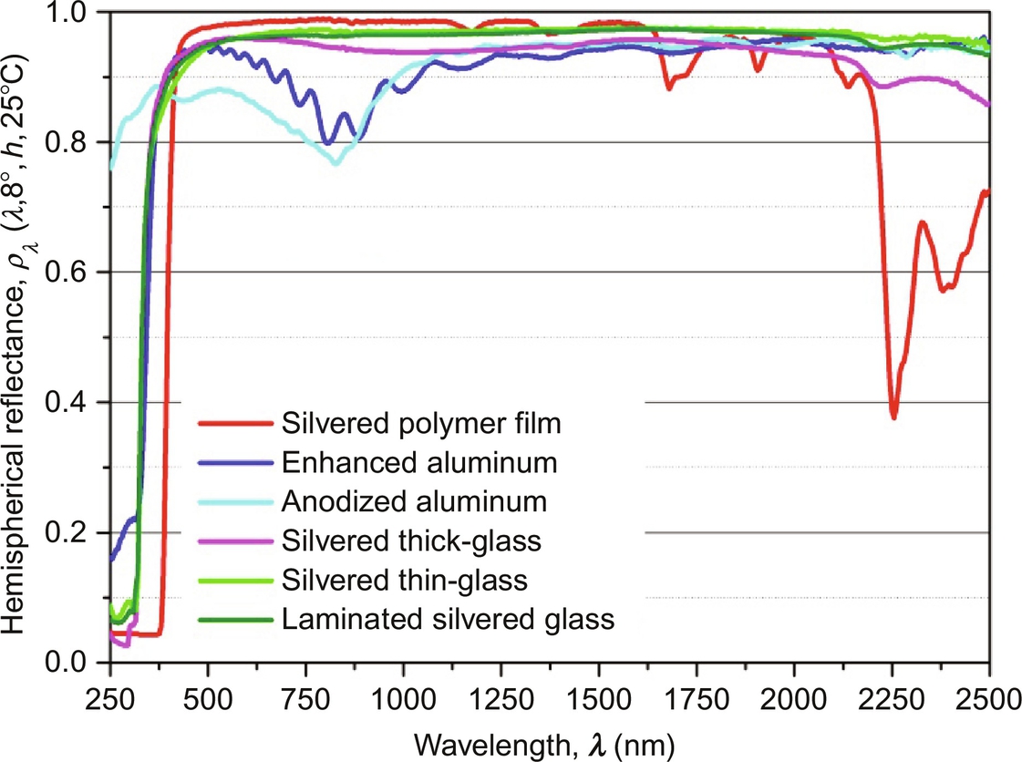
The solar hemispherical reflectance was calculated according to Eq. (3.3) and using the direct solar irradiance spectrum from the ASTM G173-03 standard [15] (see Section 3.2). According to the obtained values shown in Table 3.1, the same tendency previously described is observed. A range of reflectance values was indicated in this table to include the typical data recorded for several different mirror manufacturers.
3.4 Measurement and assessment
The solar mirror performance influences the overall efficiency of a concentrating solar system via two main mechanisms. The first one is the reflection of the incident solar radiation energy by the mirror, with a theoretical maximum of 100% reflectance (0<ρ<1). This effect depends on the optical properties of the reflector material and the spectrum of the radiation, and is included in the reflectance optical property (see Section 3.2.2). The second mechanism is the redirection of the incoming sunlight by reflecting it in the direction of the receiver. For this mechanism, an adequate (typically concave) shape of the reflecting surface is required. The quality of the shape or deviations of the mirror curvature (also slope) are responsible for the amount of rays hitting the receiver at its designated location. The effect of necessary tracking of the mirror system and support structure with the sun path are not considered at this point (see Section 5.2.2.3). The mirror surface quality at microscopic level, including reflector material flatness, surface roughness, and imperfections, may lead to scattering (also beam spread, haze, etc.) and the resulting effect is included in properly defined reflectance parameters. The mirror surface quality at macroscopic level, concerning mirror panel shape, is described with geometrical quality parameters, typically with slope deviation statistical values used to estimate the intercept factor (see Section 3.2.3). This section describes the measurement methods for evaluating both mechanisms in terms of performance at material and component level of the solar mirror, including the effects of the outdoor application.
3.4.1 Optical efficiency
To obtain the required information about the optical efficiency of a solar reflector, the solar specular reflectance must be measured, at the proper incidence and acceptance angles (see Section 3.2.2). Once the reflector is installed outdoors, two main sources cause a decrease of the initial reflectance values. The first is the soiling deposition on the reflector surface. In this case, the initial reflectance value can be restored by applying a suitable cleaning process. The second reason is the aging of the material due to the environmental stress. In this case, the degradation is permanent. Research is being performed to predict and reduce the effect of the degradation mechanisms (see Chapter 6).
The reduction in the reflectance takes place because of two physical mechanisms. The first is absorption, defined as the decrease of the reflected beam because part of the incident radiation is absorbed by the material. The absorption mechanism may be augmented by both the reflector aging along the time (see Fig. 3.13 left) and the soiling deposition on the reflector front surface (see Fig. 3.13 right).

The second reflectance decrease mechanism is the scattering. In this case, the intensity of the reflected beam can be constant, but the reflection angle is not the specular one, i.e., a scattering or beam spread occurs. This case may also be increased by both reflector degradation due to aging (see Fig. 3.14 left) and soiling deposition (see Fig. 3.14 right).

The following sections describe the methodology normally used to measure the reflectance, assess the durability, and evaluate the soiling.
3.4.1.1 Reflectance measurement
Suitable instruments to measure specular reflectance over an appropriate range of λ, θi, and φ are required to assess solar reflector materials properly. A suitable measurement protocol is required not only to provide all the information to assess this kind of materials, but also to guarantee that values given by different manufacturers and independent institutions are comparable among them.
An international group of experts has been created under the framework of the International Energy Agency (IEA) SolarPACES Task III, collaborating on the project “Development of guidelines for standards for CSP components.” The goal is to collect and prepare recommendations of procedures and protocols to be presented to the standardization organizations and further translated into national and international standards. Concerning the reflectance measurement topic, guidelines titled “Parameters and method to evaluate the solar reflectance properties of reflector materials for concentrating solar power technology” were published [10]. A new version of the document is currently under preparation.
These guidelines contain the properties of the optimum instrumentation needed to evaluate adequately all solar reflector materials for CSP applications. As this ideal instrument does not currently exist, the minimum requirements for selecting existing and future instruments to best characterize the minimum relevant reflector parameters were also specified. These ideal requirements are summarized as follows [10]:
• λ range between 280 and 2500 nm, according to the range of the solar spectrum [15], and λ intervals which allow accurate solar weighted calculations, with a maximum interval of 5 nm. In some instruments cost can be greatly reduced by avoiding the use of an extra UV-lamp and starting the measurement at 300 nm. This is allowed since the UV and NIR tails have low impact on the final average value. As a minimum requirement, the specular reflectance must be measured at several (at least three) narrow λ range appropriately spaced along the solar spectrum or at a specified range that accounts for differing λ dependent scattering properties.
• Various θi ranging from near normal (θi≤15 degree) to at least 50 degree or an innovative approach to obtain the reflectance as a function of θ. When this is not possible, the reflectance must be measured at least at near normal incidence.
• For specular reflectance, several precise and selectable acceptance apertures or an innovative approach that covers a range of φ appropriate to measure the specular reflectance as a function of φ. Specular reflectance measurements must be carried out at least from φ>0 to φ≤20 mrad.
• For hemispherical reflectance, if an integrating sphere is part of the setup, its size needs to be adequate to minimize errors. A diameter of at least 150 mm is recommended.
• Absolute measurements are taken, thus no reference mirror is necessary. If it is not possible to achieve this requirement, measurement must be done with a stable, calibrated reference mirror.
• Adjustment options for correcting beam alignment, to account for different mirror thicknesses and surface curvature.
• Measurement spot size as large as possible, with the option of reducing size in case of interest.
• All measurements included in the process of obtaining the desired result should be done at the same spot on the sample and with the same instrument.
• Noncontact measurement to avoid damaging the surface.
• Portable for field measurements, which implies high battery autonomy, battery status display, light-weight, small compact size, easy to handle, robust, and digital data storage.
• A coordinate system that is incorporated in the instrument to identify the position of defect points on a mirror and study their evolution over time would be a useful addition for monitoring quality.
• Low and stable type-B uncertainties [33].
• No influence by external stray light.
• No risk to human health or environmental hazard involved.
Although the ideal instrument accomplishing all desired requirements to measure reflectance of solar mirrors properly does not exist on the market, several items of marketed equipment are commonly employed. A brief description of these devices is given next.
Spectrophotometers
A spectrophotometer is an instrument consisting of a spectrometer for producing light of any selected λ, and a photometer for measuring the light intensity. The use of these instruments is widely extended in the industry (mainly in chemistry) to measure optical properties (transmittance, absorptance, and reflectance) of both liquids and solid materials.
Concerning the list of requirements for instrumentation presented above, the main advantage of a conventional spectrophotometer is that the reflection can be measured over the entire solar spectrum because these instruments usually utilize two light sources and a monochromator to scan the near UV, visible (vis), and NIR spectrum in desired wavelength intervals. The main disadvantages are that they are not portable and thus can only be used in laboratories. They do not offer beam adjustment, adaptation to mirror curvature, or different mirror thicknesses. Measurements are typically taken at a near normal incidence angle of θi=8–15 degrees.
Both specular and hemispherical reflectance can be measured with spectrophotometers depending on the accessory coupled. Integrating spheres are widely employed to measure hemispherical reflectance accurately. Although several accessories to measure specular reflectance with a spectrophotometer are available, most of them still have important disadvantages. The simplest method is to use the integrating sphere specular opening port (or light trap) to measure diffuse reflectance and later calculate specular reflectance by the difference between hemispherical and diffuse components. However, this method is not recommended for CSP applications because the resulting φ is too large (around 80 mrad). Another example of specular accessory is the Universal Reflectance Accessory, which measures at several θi but with unknown φ (estimated to be around 100 mrad).
The spectrophotometer commonly used is the Perkin Elmer (PE) Lambda 950 or Lambda 1050 (see Fig. 3.15) [34], or similar. The PE scanning spectrophotometers models Lambda 950 and 1050 are UV-vis-NIR double beam and double monochromator ones with two light sources: a deuterium lamp for the UV range and a halogen lamp for the vis/NIR range. The beam source has a spectral range from 175 to 3300 nm, θi=8 and about 12.0×4.5 mm2 size.

Reflectometers
Reflectometers are measurement devices that measure the intensity of the light source after reflection on a sample at a few λ or even at only one. After calibration with a known reflectance reference standard, the measured intensity is automatically transformed into a reflectance reading by correlating the measured flux intensities of the reference standard and the sample. Most reflectometers give readings of specular reflectance at near normal incidence and one or several selectable φ. In addition, there are some instruments that incorporate a small integrating sphere to measure hemispherical and diffuse reflectance thanks to a specular opening port.
The main advantage in this case is portability, which makes reflectometers useful for quality control and/or cleanliness assessment in the solar field. In this sense, the following requirements are important when choosing a suitable instrument for on-site measurements:
• size and weight that allow a single operator to use it even overhead
• easy handling and robustness
• short measuring time
• mechanism for beam adjustment and positioning easily accessible and controllable
• stable and durable calibration mirror
• capable of measuring on curved and/or second-surface mirrors
• ideally the possibility of storing the digital data in addition to a display reading
• high battery autonomy, indication of battery status, and no influence of the battery level on the readings
• stability in the typical operating environment of a CSP plant (this includes high, low, and variable ambient temperatures, relative humidity, wind, and dust)
• capable of working in strong sunlight without stray light problems
The portable reflectometer most commonly mentioned for reflectance measurements of solar reflectors is model 15R-USB manufactured by Devices and Services (D&S; see Fig. 3.16) [35], μScanTM manufactured by Schmitt Measurement Systems [36], Condor by Abengoa [37], CM-700d/600d by Konica Minolta [38], and 410 Solar by Surface Optics [39]. Also, the PFlex developed by Fraunhofer-ISE has recently been marketed by PSE [40]. Among them, the reflectometer most commonly used to measure monochromatic specular reflectance is the 15R-USB by D&S. It has a light emitting diode (LED) source of λ=[635, 685] nm, with a peak at 660 nm. A new version of the instrument is capable of measuring at λ={460, 550, 650, 720} nm. φ can be selected from φ={3.5, 7.5, 12.5, 23} mrad. First- and second-surface mirrors can be measured by modifying a screw located on the central side that controls the mirror-glass thickness. In addition, it allows measuring curved mirrors using two adjusting screws situated on its base. With these two screws, the optical measuring system is aligned and adapted to the curved surface [35].

3.4.1.2 Soiling evaluation
Reflectance of mirrors continuously suffers a decrease due to outdoor exposure to the environment in the solar field, which can provoke a significant decay in the power production of a CSP plant. The soiling rate in a CSP plant depends on the type of reflector and the plant location. The type of reflector affects the soiling rate because particle adhesion to the top surface is influenced by the material properties [41]. With respect to the location, several aspects must be considered, such as: weather (rain profile, humidity, wind speed and direction, temperature, dew formation, etc.); closeness to coasts, industrial areas, cities, roads, and zones with high pollution; fauna and flora (specially the presence of seeds); and particle (dust and sand) concentration, size, and chemical composition.
A deep review about the impact of dust accumulation on the use of solar energy (including photovoltaics, concentrating photovoltaic and CSP systems) was published in 2013 [42] and has recently been updated [43]. Several research studies about reflectance losses of solar reflectors due to dust accumulation in outdoor exposing were conducted in different locations. Table 3.2 includes a summary of some representative studies.
Table 3.2
Summary of some representative studies about soiling rates
| Site | Type of reflector | Exposing time | Year of publication | Reference |
| Five sites in United States | Silvered glass, aluminized acrylic and aluminum coated with silicone elastomer | 1 year | 1980 | [44] |
| Albuquerque (United States) | Silvered glass | 3 years | 1981 | [45] |
| Crosbyton (United States) | Eight types (silvered glass, aluminum and polymer film reflectors) | 3 years | 1981 | [46] |
| Seven sites in United States | Silvered glass and acrylic film | 1 year | 1986 | [47] |
| Negev desert (Israel), Sicily, Freiburg (Germany), Arizona (United States) and Florida (United States) | Silvered glass and aluminum | 100 days (Sicily, Freiburg and Arizona), 700 days (Negev desert), 800 days (Florida) | 2010 | [48] |
| Almeria (Spain) | Silvered glass | 9 months | 2012 | [49] |
| Almeria (Spain) | Silvered glass | 2 years | 2014 | [50] |
| Al Wagan and East Jabal Hafeet (UAE) | Silvered glass | 1.5 years | 2015 | [51] |
| Oujda (Morocco) | Silvered glass and aluminum | 3 months | 2016 | [52] |
| Agadir (Morocco) | Silvered glass and aluminum | 6 months | 2016 | [53] |

3.4.1.3 Durability assessment
Degradation of the mirror surface can be cost-intensive. NREL has measured an annual degradation rate of 0.2% (pp) in hemispherical reflectance for silvered-glass mirrors exposed in different climate conditions in the United States [54]. The examined mirrors contained high contents of lead in the protective paint layers for enhanced durability. For environmental reasons, the lead content of the prime and intermediate coat has been reduced from 20 to 2.5 wt% and 10 to 1 wt%, respectively. Furthermore, a tendency towards lead-free mirrors (<5 ppm Pb) is desirable, but the durability of these products has not yet been proven. Higher degradation rates than 0.2% (pp) are expected for newer materials with a low Pb-content. Additional losses may occur during the exposure in desert sites with high wind speeds and dust content due to glass erosion and the associated reduction in specularity caused by wind blown particles.
For example, if we assume an annual degradation rate of 0.3% (pp) in specular reflectance in a 200 MWel power plant with an annual capacity factor of 40% (like the Noor-2 plant in Morocco), the loss in reflectance equals 0.45 less efficiency per year. On average, over the lifetime of the plant (20 years), the electricity production will be reduced by around 4.5%. For a revenue of 0.14 US$/kWh, the cost of degradation can then be calculated to≈88 million US$, which could be at least partially saved by using durable reflector surfaces.
The high impact of the component durability on the revenue over the plant lifetime raise the importance of durability assessment. For this purpose, solar reflectors are tested in accelerated aging tests, at increased levels of humidity, radiation and in interaction with corrosive or erosive agents, etc. Predicting the lifetime of the material in service based on the results of accelerated tests is a complex task. Correlations between three outdoor reference sites and a specifically developed accelerated aging testing sequence have been derived for aluminum mirrors as described in Chapter 6 (accelerated aging methodology). Developing such correlations requires to monitor the degradation outdoors of exposed samples in different climatic environments as reference for the accelerated tests. The research for a proper accelerated aging testing sequence for silvered-glass mirrors is still ongoing and standardization committees (e.g., AENOR GT2) are currently working on this issue [55]. For more details, see Chapter 6 (accelerated aging methodology).
3.4.2 Geometrical quality
Several optical and non-optical methods have been adapted for measuring mirror shape described in Section 3.2.3; both aim at determining either the normal vector of the reflecting surface directly, or measuring 3D coordinates of the mirror surface and calculating normal vector afterwards. In any case, high resolution and complete coverage of the mirror area, in particular near the mirror borders, is required.
This section focuses on definitions and measurement methods on the component level (e.g., single mirror panels). Measures and methods applicable on the system level for entire concentrators are described in detail in Section 5.2.
3.4.2.1 3D measurement with photogrammetry
Close range photogrammetry methodology [56–58] builds a 3D model of a point pattern attached on the mirror surface analyzing the information of several digital images captured from a wide range of viewing positions (Fig. 3.17). The points of interest have to be highlighted by special markers. The application of these markers to the collector surface or structure means a high preparation effort. However, results of the photogrammetry consist of 3D coordinates of the point pattern. By applying geometrical methods (Delaunay triangulation, Sobel filters, etc.) to the coordinates obtained by photogrammetry, local slope vectors between adjacent points can be obtained in order to calculate SDx and SDy values.

Spatial resolution of photogrammetric measurements is limited by the point pattern density, ranging from more than 1000 points per square meter for single facet sizes (1–3 m2) to around 100 points per square meter for whole heliostats or PTC (more than 50 m2) [59].
As photogrammetry can be applied in any mirror position, it is very helpful not only to compute mirror slope deviation parameters SDx and SDy, but also to measure for example, deformations at different positions due to gravity or different loads conditions (see Fig. 3.18), or time-dependent deformations using video-photogrammetry (e.g., wind effect on mirror shape). More examples of photogrammetry are given in Sections 5.2.2.2 and 5.2.3.1.

3.4.2.2 Slope measurement with deflectometry
Deflectometry is performed with an optical measurement system for high resolution and high precision quality assurance measurements of the shape of mirror panels or larger concentrator units. It uses a non-contact optical measurement and digital image processing technique based on the deflectometric measurement principle (Fig. 3.19). This measurement technique was developed at DLR and specifically optimized for the measurement of shape deviations of concentrating solar reflector panels [60,61]. It has been adapted to industrial requirements and is applied in industrial production quality control. Regular line patterns of different resolution, phase-shift, and orientation are projected on a flat white target of sufficient dimensions; a digital camera takes images of the reflected line patterns seen in the mirror object (Fig. 3.20); and a control unit performs the image processing and evaluation for calculating the local normal vectors of the reflecting surface. Fig. 3.21 shows resulting maps of RP3 type parabolic trough mirror panels in local slope deviation of the normal vector, and in focus deviation of the reflected rays. The measurement duration has been below 10 seconds for automated inline systems.


The spatial resolution of the result depends on the camera resolution and mirror size and is typically 1–3 mm on mirror panels. Accuracy and reproducibility are around 0.1 mrad and are backed by reference measurements on transfer standards and on a water surface. Ongoing work in research aims at reducing the influence of mirror shape deformations due to the tracking angle or the assembly accuracy [62]. Applications and specific deflectometry methods for large scale concentrators applicable in the solar field are presented in Section 5.2.2.1.
3.4.2.3 Slope measurement with laser reflection scanning
The Video Scanning Hartmann Optical Test System (VSHOT) is a laser ray-trace system to characterize both point and line-focusing concentrators [63]. Such scanning approaches are rather time-consuming when high spatial resolutions are required. A computer-controlled laser scanner and digital-camera image acquisition are used to provide optical surface contour data. The incident laser beam is parallel to the optical axis of the system. The laser scans a mirror in a pattern predefined by the user/programmer. At each scanned position, the laser beam is reflected back to a target and the location is imaged using a camera. The surface slope is calculated at each scanned position using the laser output angle and return-spot location.
The laser reflection scanning method can be used in the forward configuration as described above with the incident laser beam parallel to the optical axis of the system and the target at the focal point or line. But a reverse configuration is also possible, where a point light source is placed in the focus and the camera scans the mirror in a predefined pattern.
Laser reflection scanning techniques have been adapted to measure reflector panel shape accuracy in laboratory quality control as well as in field setups [64–66], as can be seen in Fig. 3.22.

3.4.2.4 Laser radar
Recent development of commercial laser-scanner has improved very significantly their accuracy, allowing the use of those systems as an alternative to photogrammetry for shape assessment of mirrors and facets. Since laser scanners also offer 3D coordinates of the mirror surface, the procedure will be the same as photogrammetry methods, with the advantage that point density is higher with laser-scanners, allowing the measuring of more than 100,000 points per square meter. On the contrary, the reflecting surface must be painted to avoid specular laser reflection, or measurements must be done on the rear side of the mirror. Fig. 3.23 shows the measurement setup of a heliostat facet using a laser-scanner.

3.5 Future trends
The materials roadmap published by the European Commission in 2011 establishes that the materials R&D and the related product development with respect to CSP mirrors in the coming years should be focused on the following aspects:
• Apply research to further develop low-lead solutions towards “Zero Lead” mirrors with long-term corrosion protection against weathering.
• Develop advanced mirror protective coatings with antisoiling function and high abrasive resistance.
• Improve resistance of non-glass mirrors to surface degradation in different climatic conditions and under abrasion; develop improved accelerated aging tests.
• Apply research for low-iron glass with reduced transmission losses, method for recycling process, method for treatment of raw materials to reduce the iron content.
• Develop reflector materials with high-temperature stability suitable for secondary reflectors (Fresnel, central receivers).
• Develop accelerated aging testing taking into account specifications of different applications and loads (primary, secondary, climate variability, abrasion, etc.).
One of the key technological milestone stated by the IEA for 2018 in its roadmap is the development of light-weight, low-cost reflector optics [67]. According to this document, this action should be driven by CSP industry with support from research institutions.
Finally, it is worth mentioning that the strategic research agenda (2020–25) elaborated by the European Solar Thermal Electricity Association (ESTELA) also reports on the baselines for short- to long-term research for solar thermal electricity technology. Concerning reflectors, several research priorities are identified [68]:
• Develop light-weight and durable reflective surfaces.
• Enhance antisoiling properties of reflectors to reduce water consumption.
• Increase the reflectance of glass-based reflectors by increasing the transmissivity of glass.
With respect to reflectance measurement procedures, a simplified method has recently been published to evaluate mirrors with high specularity, using the state-of-the-art instrumentation [69]. This procedure is being included in the updated version of the SolarPACES Reflectance Guidelines, which will be referred to by national and international standards under development [55]. In addition, research centers and companies are currently working on the development of instruments to characterize properly the optical efficiency of solar mirrors by measuring solar-weighted specular reflectance, satisfying all the requirements previously established in Section 3.4.1 [70–74].
A detailed description of future trends a concerning geometrical assessment is included in Chapter 5.