
5Designing the POLCA System for Your Situation
Once you are convinced that the prerequisites for POLCA are in place at your company—or at least that they will be sufficiently addressed prior to the POLCA launch—you can proceed with designing the system. This chapter will cover the major points that will help you design and customize the details of the POLCA system for your particular situation.
There are several details and possible special situations to consider, so this chapter is divided into the following major topics to help you navigate through all the issues:
Creating a POLCA Implementation Team and designating a POLCA Champion.
Determining all the POLCA loops.
Laying out the POLCA Chains.
Deciding on details related to the POLCA cards.
Adding the finishing touches with some final details.
Each of these topics will be covered in one of the following sections in this chapter.
Create an Implementation Team and Designate a POLCA Champion
POLCA implementation needs to be carried out by a cross-functional team composed of manufacturing managers, planners, schedulers, selected operators from the cells involved, material handlers, and other shop floor personnel who would be influenced by the implementation. We also recommend including someone from Human Resources: the importance of this will become clear from chapters that follow. So, the first step in implementation is for management to put in place a POLCA Implementation Team. As part of this, at the outset, management should designate one of the team members as the POLCA Champion. This person should attend POLCA training sessions, do the background reading, and learn enough about POLCA in order to serve as the in-house expert on the system. Thus, the POLCA Champion can be the central point of contact to whom questions regarding the design or operation of the POLCA system can be directed. The POLCA Champion also serves as the liaison between the Implementation Team and upper management.
During the implementation, management should not expect the POLCA Champion to take on these tasks in addition to his or her regular duties. Depending on the size and complexity of the proposed implementation, management should reassign some of this person’s duties. Based on successful implementations we can state that, typically, POLCA Champions have had 50% or more of their existing workload reassigned so they can devote sufficient time to the POLCA implementation.
Begin by Determining All the POLCA Loops
The first step in designing your POLCA system is to decide on the set of POLCA loops. This can be done using the procedures described in this section, which will cover these points in following subsections:
How to identify all the POLCA loops if you want to implement POLCA throughout your shop floor.
An important note about not including stocking points in the POLCA loops.
The process for determining the loops if you will implement POLCA in only a subset of your shop floor.
Deciding on whether to put in single or multiple loops for a given area.
Based on the goals that you laid out during the Pre-POLCA Assessment (Chapter 4), decide first whether you want to implement POLCA throughout your shop floor, or if you want to begin with a test implementation as a proof of concept for a limited portion of your operation. Reviewing the case studies in Part III of this book will help you with this decision. In general, smaller companies have decided to launch POLCA at one time throughout their shop floor, while larger companies have started with a limited area as a test case. Examples of smaller companies that launched POLCA throughout their shop floor are BOSCH Hinges (Chapter 12), Szklo (Chapter 14), and Preter (Chapter 15); a larger company that started with a partial implementation and then extended it to the rest of the factory is Alexandria Industries (Chapter 10). A different factor to be considered is provided by the example of Patheon (Chapter 11)—although this is a large company, due to the interlocking of routings throughout their factory they decided that it would not be easy to demarcate a subset for a POLCA trial, and so they launched POLCA all at once for the whole plant.
Even if you intend to implement POLCA only in a portion of your shop floor, you should still read the section that follows as there are several situations that you should learn about which apply in both cases.
Implementing POLCA throughout Your Shop Floor
If you intend to launch POLCA throughout your operations, then the POLCA loops are determined using this procedure. The starting point is the process by which jobs are released to the shop floor. (As a reminder, we defined what we mean by “job” in Chapter 4.) Smaller manufacturing companies usually have a person typically called a planner or scheduler that releases jobs. In larger companies, there may be a group of people, and in a similar way they may be called the planning or scheduling group. We will refer to this person or group of people as the Planning Cell. (For now, we will assume that the main function of the Planning Cell is to review the set of jobs that should be released on a given day, and for each such job, checking that the needed material is in stock, and then preparing the work order and shop packet for the job. Later in this chapter we will consider the situation where the Planning Cell may be involved in some more tasks too.) If you have more than one planning team that can release jobs, then you will have multiple planning cells, and you can repeat the logic here for each of the planning cells. This could be the case, for example, when a company has two teams of planners, each one serving a particular subset of the company’s customers.
We will continue our description for the case where there is one Planning Cell; let’s call it PC1. You should actually start your POLCA loops at the Planning Cell; this was mentioned briefly in Chapter 2, and we will provide more reasons behind this recommendation later in this chapter. Therefore, you will need a POLCA loop from PC1 to each cell to which PC1 could release a job as the first step in the routing. Asking the Planning Cell team about this will identify this first set of loops. There are some additional considerations with regard to the starting point in a job’s routing; these will be discussed in the section “Lay Out the POLCA Chains” later in this chapter.
You have now identified the first set of POLCA loops from PC1 to some destination cells. Next, take each cell on the shop floor in turn, and for that cell ask the Planning Cell team: When jobs are completed by this cell, what other cells might those jobs go to next? For example, if jobs from Cell A can potentially go to Cell D, G, and K, then you need to plan for three POLCA loops: A/D, A/G and A/K. You perform the same analysis for every cell, and this generates the complete set of POLCA loops.
If you are in doubt whether jobs flow between certain cells, analyze some historical data on routings of jobs, for instance over the last six months. But don’t worry about getting it perfect because it is easy to add POLCA loops later! In fact, as job characteristics change or new products are added, you will need to modify your POLCA loops from time to time anyway. So, take a first stab at the set of POLCA loops and get started.
To assist you with documenting your POLCA loops, we now return to the convention for drawing the POLCA loops that was introduced in Chapter 2. This convention facilitates unambiguous interpretation of POLCA system diagrams. This will be important during the process of designing your POLCA loops, as well as for documenting the final loops for your employees. The convention is that standard POLCA diagrams must follow three rules:
The circulation direction of POLCA loops is always clockwise.
The part of the loop that represents jobs going along with cards from the origin cell to the destination cell has arrows on it.
The part of the loop that is the route for returning cards does not have arrows on it.
Figure 5.1 shows why this convention is needed. Although in Figure 2.3 in Chapter 2 we displayed the A/B POLCA cards, which helped to indicate that this was an A/B loop, in a more complex diagram of the shop floor with many loops you may not want to crowd the diagram with cards. So then, if you see a loop connecting two cells, such as the first loop on the left side of Figure 5.1, it is not clear if this is an HT/MC loop or an MC/HT loop. Also, if you put arrows on both sides of the loop to indicate circulating POLCA cards as in the second loop in Figure 5.1, this representation would be identical for an HT/MC loop and an MC/HT loop, so once again it is ambiguous. On the other hand, the two loops on the right side of Figure 5.1 show how this convention would clearly distinguish between the two situations. Also note that if you are reviewing a complex shop floor diagram with many POLCA loops, and you see a part of a loop without arrows on it, the convention tells you clearly that this is a path for returning cards, and further, even without the arrows on this part of the loop the direction of flow of the cards is clear because it is always clockwise.

Figure 5.1Illustration of the convention for clarifying the direction of POLCA loops.
The depiction of the actual POLCA loops on a shop floor diagram is an important way of conveying the flow of POLCA cards to the personnel involved. However, for situations involving a large number of POLCA loops on a complex shop floor layout, there is an alternative that keeps the diagram less crowded, and that is to use arrows linking each originating cell with its downstream cells. This approach is used in the descriptions of some of the case studies in Part III of this book; for examples, see Figures 10.6 and 11.1.
We now remind you of the term POLCA Chain introduced at the end of Chapter 2. This refers to the sequence of POLCA loops that a job will encounter as it goes through its complete routing, using the metaphor that the POLCA loops are like interlocking links on a chain as shown in Figure 2.9.
As part of determining the POLCA loops, you need to identify cells that are possible ending points for a POLCA Chain. Note that some cells may be in the situation that they are the final steps in some jobs’ routings, but they are intermediate steps for other jobs. For example, a machining cell may be the last step for parts that are being shipped out as spares to customers, but it may also deliver parts to an assembly area in the factory. There are some important considerations for cells that serve as the end point of any POLCA Chain: these are discussed in a following section.
It isn’t necessary that the POLCA loops only go between cells. You can also include standalone resources. For example, if you have an oven, or a specialized machine, and jobs need to go from various cells to that resource and back, you can include that resource in the POLCA loops as well, just as you would a cell. This situation was shown in the MMC company example in Chapter 2, and in the POLCA Chain of a job at MMC in Figure 2.9.
There is also no problem if jobs go back and forth between two cells (or standalone resources). Using the situation illustrated in Figure 5.1, say a job starts at the Machining Cell (MC) then needs to go to Heat Treatment (HT) for some stress relief, and then returns to MC for additional machining operations. Then you will have an MC/HT loop with MC/HT cards as well as an HT/MC loop with HT/MC cards, and the normal POLCA rules will work just fine for jobs going in either direction. Figure 5.2 shows how you can clearly indicate both loops in your POLCA diagrams. (Note: if your routings can result in a cycle, you need to be careful; this is discussed in detail in Chapter 6.)

Figure 5.2It is possible to have loops going between cells in both directions. The figure illustrates how both the loops can be clearly shown in a diagram.
If jobs leave your shop floor to go to subcontractors, you can also incorporate this in your POLCA loops. For example, let’s say some jobs need to go off-site for a plating operation and then they return to your factory for finishing operations. This situation can be easily managed within the POLCA system, and is discussed later in this chapter.
Do Not Include Stocking Points in the POLCA Loops
In the process of identifying the POLCA loops, you must bear in mind a critical rule: Do not include any stocking points in the POLCA loops! If jobs sit in staging areas as they are waiting to be moved or to be processed at the next cell, this would be considered work-in-process (WIP) and is okay. However, areas where parts sit in buffers as some kind of intermediate stock or finished goods stock must not be included in POLCA loops. Consider a company that manufactures shafts and has a cell that prepares stainless steel bar stock for later operations. Let’s call it the Turn and Cut (TC) Cell. TC consists of machines that straighten long bars, then turn their outside surfaces to four different diameters, and next cut the bars into seven different lengths, and finally mill and chamfer the faces of the cut parts. This results in 28 different cut parts. These 28 parts are made ahead of time and stocked in a buffer. When an order is received that uses some quantity of one of these parts, that quantity is picked from the stocking point and proceeds for additional machining operations. This is an example of a buffer of semi-finished goods that has been put in place to reduce the lead time for customer orders. You must not instrument a POLCA loop to go into or out of this type buffer, nor into a finished goods buffer.
Working through an example will help to see the reason for this rule. For the shafts company above, let’s call the buffer SFS, for semi-finished shafts. If you (incorrectly) put in place a POLCA loop from TC to SFS, consider what will happen to jobs that are placed in SFS if those particular parts wait for several weeks before they are needed for an order. All those jobs will carry TC/SFS POLCA cards that will not be returned to TC. Meanwhile, TC has capacity and could work on jobs to make other parts that might be needed in SFS. But the lack of TC/SFS POLCA cards will shut TC down and it won’t work on those jobs. This is obviously not the right course of action, since TC has the capacity to do those jobs that are needed. Hence the correct approach is to not have a POLCA loop from TC to SFS.
This example once again serves to highlight a key difference between POLCA and Kanban, discussed in earlier chapters. Kanban is an inventory signal, and it could be one of the methods used to manage stock in a buffer such as the one above. However, POLCA is a capacity signal, and it would be a mistake to attempt to use POLCA to manage inventory. As discussed in earlier chapters, this is one of the reasons that Kanban is not the right approach for HMLVC environments, while POLCA is effective in these situations.
Note that you can still use POLCA when you have semi-finished or finished goods stocking points in your operations, but you need to be aware of how to use POLCA along with your MRP system to manage these stocks. Essentially, the MRP system—possibly guided by your planners—will create work orders to either use or replenish these stocked items. More specifically, to use a stocked item, the work order will start with the first cell that this stocked item must go to, with the stocked item being part of the material to be picked for the work order, while to replenish a stocked item, the work order will end at the stocking buffer. Then these work orders will simply flow through the POLCA system like any other job. (See the discussion surrounding the definition of a “job” in Chapter 4.) The key point to note here is that the POLCA Chain for the material going into the stocking point is terminated, and a new POLCA Chain is started when the material is picked, so we do not have a POLCA Chain that goes through this buffer. Later sections discuss in more detail about the starting and ending points for POLCA Chains, so those sections will also clarify how these work orders would operate.
Implementing POLCA in a Subset of Your Shop Floor
In the case where you have decided to start with a trial of POLCA in a portion of your operation, you need to decide which cells should be included in this initial implementation. To arrive at this decision, there are two main factors to consider:
The chosen subset of your operations should include products and processes that are experiencing significant issues described in Chapter 4—such as late deliveries, frequent rescheduling, numerous hot jobs, and other issues listed in that chapter—for which POLCA is a potential solution. The aim is that after implementing POLCA it should be clear if it helped alleviate these problems and make significant improvements in the key metrics for these products and processes.
The subset must be relatively self-contained in the sense that interactions with other job flows need to be limited in the following way. If a particular cell will be the downstream cell in any POLCA loop, then ideally, all jobs arriving at that cell need to be included in the POLCA system; in other words, all arriving jobs need to be carrying POLCA cards. The reason for this is as follows. A POLCA card being sent back to an upstream cell signals that there is available capacity in the downstream cell. If some jobs are on POLCA and others are not, then the Decision Time rules are no longer clear at the downstream cell. When a job that is not on POLCA arrives at this cell, when should it be started? If you start such a job based on some other rule like “first-come first served,” or based on its Authorization Date, then it would use capacity without using a POLCA card and hence invalidate the capacity signals for the POLCA system and could cause bottlenecks. Thus, the test of the POLCA system for your subset would not be fair in these circumstances.
So, during the process of choosing the subset, you should go through the logic of each cell visited by jobs that might be in the subset, and ask the same question as for the previous case: When jobs are completed by this cell, what other cells might those jobs go to next? For each of those destination cells, you have two choices: either the cell will be included in the subset using POLCA, or you can terminate the POLCA operation prior to this cell. For any cell that you decide to include in POLCA, you will then go through the same procedure, until you have identified all the cells that will be included and the boundaries of the POLCA loops.
An example will help to see how to use the process and that it is quite intuitive. Let’s revisit the MMC factory described in Chapter 2 and shown again here in Figure 5.3. Let’s say the cells at MMC are working well within themselves, but the teams are complaining that there is a mismatch in the schedules and workload through the Heat Treat (HT) operation, with high variability in the lead times through HT, and as a result, a lot of expediting and rescheduling of jobs through this area of the shop floor. The company’s preliminary analysis of various factors (as described in Chapter 4) indicates that POLCA might be a good solution for the company as a whole, but first they would like to try it out in a limited way for this portion of the operation.

Figure 5.3Initial idea about the portion of the factory for the POLCA trial at MMC.
Upon further investigation, they find that the Welding Cell before HT and the Large Milled Parts Cell following HT are the most impacted by the expediting and rescheduling. Let’s denote these two cells by WE and LMP respectively. So MMC begins by considering a limited POLCA implementation involving only these cells; the POLCA loops they are considering are WE/HT and HT/LMP, see Figure 5.3. (If this seems too small of an implementation, note that Alexandria Industries started with just such a small implementation and immediately experienced substantial results which convinced them to go with a broader implementation, as described in Chapter 10.)
The next step is for the company to go through the “self-contained” tests explained above. Since HT will be a downstream cell, all jobs arriving at HT need to carry POLCA cards. For this example, let’s assume that all the possible job flows at MMC are represented by the arrows connecting the boxes in Figure 5.3. From the figure, you see that the Rotational Parts Cell (RP) also sends jobs to HT. This implies that for a successful trial of POLCA, the company must include RP in the subset for the trial. Next, note that LMP will also be a downstream cell. However, since it only receives jobs from HT, and these will be on POLCA, there is no problem. This concludes the logic for verifying that the subset will be self-contained, and the result of this logic is that MMC should, at the minimum, include cells RP, WE, HT and LMP in the subset for their trial POLCA implementation. At this point the implementation team at MMC notices that since RP receives jobs from the Planning Cell (PL) it might help to smooth out RP’s operation if they also include a POLCA loop from PL to RP. While this is not required by the logical tests above, it makes sense to boost the potential for success in the trial, and having smoother flow through RP will only help. This points out that some common-sense brainstorming should also be used to accompany the decision on the subset to be chosen. As a result of all this reasoning, the final subset for the trial is shown in Figure 5.4. Also, to be clear, when jobs leave the boundary of the trial area, they will go back to flowing according to the existing system that is in use at the company.

Figure 5.4Final decision about the boundary for the POLCA trial at MMC.
In looking at Figure 5.4, you may be concerned about one aspect, which is that jobs from HT also go to the Finish Machining Cell (FM), which will not be included in POLCA. Perhaps you are already asking the question, “HT will have jobs going to LMP which is on POLCA, and to FM which is not on POLCA, so won’t this be a problem?” The key to the answer here is that for a downstream cell, the logic given above is to check that all arriving jobs need to be on POLCA. But that test is not needed for departing jobs! A later section on “Determining the Ending Points for Your POLCA Chains” will explain how this will work fine for HT. Similarly, PC will be dealing with jobs that are on POLCA and going to RP, as well as jobs not on POLCA and going to the Small Milled Parts cell. Again, note that these are departing jobs, and so for the same reason as for HT, this is not a problem.
On a related note, from Figure 5.4 you see that the POLCA Chains that come from RP to HT will actually start at the Planning Cell, and this process has already been discussed earlier in this chapter. However, the POLCA Chain for jobs going from WE to HT will actually start at WE. So, this is a new situation: a POLCA Chain starting part-way through the shop floor. A later section on “Decide on the Starting Points for Your POLCA Chains” will also explain how to do this properly.
Should You Put in Single or Multiple Loops for a Given Area?
A company that manufactured large electrical control systems puzzled over a situation that serves as a good example for this topic. The company fabricated large sheet metal cabinets in one area, and then these cabinets went to several assembly cells in other areas where the cabinets were stuffed with electrical and mechanical equipment. The cabinet area had four fabrication/assembly lines that could put together the cabinets, and then these cabinets were delivered to seven assembly cells. The question was whether to dedicate each cabinet line to serving one or more assembly cells, or to have the cabinet area available to serve any of the assembly cells according to need. The first case would require POLCA loops from each of the lines to the associated assembly cells, as shown in Option 1 in Figure 5.5, while the second case would include the whole cabinets area as one originating cell in the loops (Option 2).

Figure 5.5Two options for loops from the Cabinet Area to the Assembly Cells.
The decision on which way to go is similar to the one encountered in creating cells. Dedicating the lines is beneficial when you can take advantage of similarities in the downstream operations’ needs in order to make the upstream operations more effective, but the demand across each of these upstream dedicated lines needs to be fairly even and steady. For the company that we are discussing, it turned out that there was substantial variability in the mix of products being ordered and thus it was better to have the whole cabinet area available to make cabinets for any of the assembly cells. This provided more flexibility and so Option 2 was chosen by the company.
We have now completed the discussion of items related to POLCA loops. After you have decided on all the potential POLCA loops in your system, you need to determine how these loops will interconnect to form POLCA Chains for the routing of various jobs. This is covered in the next section.
Lay Out the POLCA Chains
The main items that you need to consider in designing your POLCA Chains are the following:
The starting and ending points for all the POLCA Chains, including some considerations when implementing POLCA only in a subset of your shop floor.
How to properly include the lead time for the Planning Cell.
The procedure for incorporating subcontracting into the POLCA system if your routings include such outside operations.
Deciding whether you will go with the standard POLCA described in Chapter 2, or an even simpler version, Release-and-Flow POLCA (explained below). To help with this decision, we identify situations where standard POLCA is recommended.
We begin by discussing the starting point for the POLCA chains.
Starting Point for the POLCA Chains
As mentioned earlier, if you intend to implement POLCA throughout the shop floor, the first loop in a given POLCA Chain should be from the Planning Cell to the first cell on the shop floor for that chain. Using the MMC factory as an example, from Figure 5.4 we see that the first shop floor cell for some jobs is the Rotational Parts Cell (RP). So, the first loop for those jobs will be from the Planning Cell (PL) to RP, as also shown in Figure 5.4. It is important to understand the reason for starting the POLCA Chain at the Planning Cell, and not at the first shop floor cell. Let’s use the RP Cell as an example. This cell has a certain capacity, and a major aim of POLCA is to hold off on sending jobs to cells that are overloaded. Suppose it has been determined that there should be four POLCA cards in the PL/RP loop. (The process for calculating the number of cards is explained later in this chapter.) The Planning Cell, being part of the POLCA system, will also need to follow the Decision Time logic. So once PL has released four jobs to RP, and if no POLCA cards have been returned by RP, this indicates to PL that RP is backlogged. Releasing more jobs to RP would not be a good idea, for all the reasons discussed earlier in this book. Hence the POLCA rules kick in at this time, and PL will hold off on releasing another job until a PL/RP card comes back.
In this example, we are assuming that as part of its work in releasing jobs a Planning Cell also sends signals to material handling people to deliver the appropriate raw material to the first cell. Using the previous example, PL will deliver the shop packet with a PL/RP POLCA card to the RP cell, while also arranging for the material to be delivered to this cell. Alternatives to this arrangement are: (i) as part of its job, a Planning Cell team also delivers the material along with the POLCA card to the first cell; and (ii) instead, part of the first cell’s job is to retrieve the necessary material for the job, in which case when the job is Authorized, the team should get the material, instead of waiting for it to arrive. You can use one of these methods, or a similar method appropriate for your company, for the operation at the first downstream cell from a Planning Cell.
Having the POLCA Chains start from a Planning Cell to various possible initial cells has another beneficial side-effect. It provides an effective feedback mechanism to the very people who are responsible for planning the work in the shop. If the personnel in a Planning Cell find that they are often waiting on a particular type of card, this indicates the need to add capacity at that downstream cell or to consider if jobs can be diverted to a different cell. Conversely, if there always seem to be enough cards of a particular type, then either a card can be removed from that loop (which helps to tighten the WIP control in that direction) or they can rethink how to use the capacity in that downstream cell.
As mentioned, larger companies may have multiple planning cells that are responsible for different areas of the shop floor, or for different segments of the business. In that case, each of those planning cells can be the starting point for the relevant routings. Figure 5.6 shows a company with three planning cells—MPPL, SMPL and LFPL—each of which is the starting point for some POLCA Chains.

Figure 5.6Illustration of starting points for POLCA Chains in a company with multiple planning cells.
Including the Lead Time for the Planning Cell
Because the first step in a job’s routing is now a Planning Cell, you also need to include the lead time for this cell in the POLCA system design. Specifically, this will affect the calculations of both the Authorization Dates and (as will be discussed later) the number of cards in the relevant loops. We will show how to determine the lead time for a Planning Cell with a few examples. These examples also illustrate the different types of tasks that might be performed in a Planning Cell.
Suppose that each day the Planning Cell’s tasks include reviewing all the jobs that are Authorized to be released on that day, and for a given job, checking that the needed raw material and necessary components are in stock, making sure that all the paperwork is available, and preparing the work order and shop packet for the job. For instance, the work order could include the number of pieces and the routing with the full sequence of operations, and the shop packet could include detailed drawings and other instructions. Since the Planning Cell is included in a POLCA loop, it must also follow the Decision Time logic before launching work into its cell. So, the Planning Cell team will look at the next Authorized job, next check if the material is available, and then make sure that the right POLCA card is available. Only then will it start working on preparing the work order and shop packet for the job. As each job’s packet is ready, the Planning Cell will deliver the packet to the first shop floor cell. This task is performed throughout the day for jobs in the list for that day. So, some jobs get released earlier in the day, and some toward the end of the day. But typically, based on past performance, you know that all the jobs for a given day can be handled during that day. Then a Planning Cell lead time of one day would be a good choice. This number should be used to calculate the Authorization Date for when the Planning Cell should review a job for release.
In the situation where the Planning Cell just does a quick review of each order that is Authorized, with minimal paperwork and other processing involved, and this does not take much time, you could simply assume a lead time of zero. As you will see later in this chapter, there is already a safety margin used in the POLCA system when calculating the number of POLCA cards, so the small amount of time used in the Planning Cell will be contained in this margin, and the value of zero will work just fine.
In the opposite situation, let’s say there is high variability in the arrivals of orders and also there are several tasks to be done for each order. For instance, the Planning Cell may also be responsible for preparing or obtaining the NC programs needed at the machines in each job’s routing, as well as issuing orders to get the tooling prepared at each machine. In this case, the Planning Cell could sometimes be backed up with work. So now you should estimate the average time that orders wait for the Planning Cell team to process and release them. If actual data on this is not easily available, a rough estimate based on discussions with the Planning Cell team will be good enough for a starting point. Or if you prefer to have better data, then for two or three weeks during the period that you are designing your POLCA system, you could collect actual data on the time that jobs take to go through the Planning Cell. Even if you have to collect this data manually, you only need to do it for a short period to get the initial lead time estimate. After that, the POLCA system will help you to refine the numbers through performance feedback to the Planning Cell, as explained above.
The decision on lead time for the Planning Cell will then be used in determining the number of cards in each of the POLCA loops originating at the Planning Cell. This calculation is explained later in this chapter.
Starting Points for POLCA Chains When Implementing in a Subset of Your Shop Floor
If you have decided to begin with installing POLCA in only a subset of your factory, there are two possibilities for the starting points of the POLCA Chains:
The first shop floor cell in a job’s routing is included in POLCA. For such a job, the POLCA Chain will start at the Planning Cell and go to the first cell, as explained previously. (An instance of this was the PL/RP loop in the MMC example above.) Note that some jobs will be on the POLCA system and others will not, so the Planning Cell will be dealing with jobs that are both on POLCA and not on POLCA. But this okay, because the rule stated earlier was for downstream cells, and the Planning Cell is an upstream cell in this loop. Specifically, your lead time calculation for the Planning Cell is based on current operations where they are doing the work to process all the jobs. The only change will be that for jobs that are on POLCA the Planning Cell will need to follow the Decision Time rules to release and move the jobs to the first cell on the shop floor, while for jobs that are not on POLCA, they can just release them in the same way as they are already doing today.
The POLCA Chain starts part-way into a job’s routing. This is the case when the boundary of your POLCA trial is such that some jobs will start at cells that are not on POLCA, and then encounter a POLCA loop at an intermediate routing step. This is the case in Figure 5.4 where you see that the POLCA Chain for some jobs can start at the Welding Cell, in other words, part-way into the routing of a job. In this situation, it is important to train the teams in cells that will be the first step in a POLCA Chain. Based on the logic described previously, a downstream cell in a POLCA loop must have all jobs on POLCA, so the normal Decision Time rules will apply for the team at this cell. However, the first cell in a POLCA Chain is an upstream cell. It could be that this first cell includes jobs that are not on POLCA. To illustrate this, let’s extend the MMC example so that the Welding Cell also deals with jobs that can go directly to Packing, which is not included in the boundary of the POLCA trial (see the “Additional routing” in Figure 5.7). This means that there are jobs being processed in the Welding Cell which do not require POLCA cards. The team in the Welding Cell therefore needs to be aware of the fact that if jobs are going to Heat Treat, then it must use the Decision Time rules for those jobs. We can state this more generally as follows. If an upstream cell in a POLCA loop processes jobs that are going to downstream cells that are not on POLCA, the team should be trained to know that jobs going to cells on POLCA can only be launched using the Decision Time rules, while other jobs can be launched based on Authorization Dates (without requiring a POLCA card). Also, such a cell will need to have a bulletin board for POLCA cards, even though the cell does process some jobs that are not on POLCA. So, for the example in Figure 5.7, with the loop from the Welding Cell (WE) to Heat Treat (HT), the Welding Cell will need to have a board where it keeps the WE/HT cards, even though some jobs in WE are not included in POLCA Chains.

Figure 5.7Additional routing from Welding to Packing.
If only part of your factory is on POLCA, then you also have to consider the interface between POLCA and non-POLCA cells at the end of a POLCA Chain. In other words, a job’s routing may go through a POLCA Chain but there may be additional routing steps at the end that involve non-POLCA cells. Next, we discuss the general issue of ending points for POLCA Chains as well as this situation.
Ending Points for the POLCA Chains
In designing your POLCA system, management of the last step in a job’s routing also needs some thought. In manufacturing, the three most common ways for a job to finish its routing are:
The job ends up at a shipping dock, waiting to be shipped out;
It is placed in stock in a warehouse or other stocking point in the factory;
It is immediately incorporated into an assembly or into a fabrication such as a weldment, so it loses its identity and becomes a part of this bigger object.
You may think there are other possibilities, but they will typically fit into one of these three categories. For example, if parts needed for assembly arrive at a stocking point near the assembly area where they are stored, and are later picked when it is time for them to go into an assembly, this is an instance of category (2) above. Note that, for this reason, in category (3) we used the qualifier “immediately” to differentiate it from this situation. As another example, consider a long aluminum extrusion that gets cut into 10 shorter pieces. These pieces will now have new part numbers and will be put into a stocking area as these new parts. Once again, this can be seen as an instance of category (2).
We will use these three categories to illustrate the thinking needed for the last steps in a job’s routing in POLCA, because this impacts the decision on the last link in a POLCA Chain. If you have a situation that is truly different, you can use the logic below as a model to help you decide on the right approach for your situation. For the first set of descriptions below we will assume that you have decided to implement POLCA throughout your shop floor. Later, we will consider the situation where POLCA is implemented in a portion of your shop floor. Here are the proper ways to end a POLCA Chain for each of the three categories above.
The job will be shipped out when it is completed. Suppose the last three steps in a job’s routing are: Assembly and Test Cell (AT); Packing Cell (PK); and Shipping Dock (SD). AT and PK are capacity constrained. However, when a job gets to SD, it is simply placed in a staging area until it is loaded onto the appropriate transport. Depending on whether the job got completed early and/or whether the relevant transport arrives as planned, the job will sit here for a variable amount of time; it takes up space, but no machine or labor capacity is involved. Thus, it makes sense to have a POLCA loop from AT to PK, but not from PK to SD. Hence the last link in this job’s POLCA Chain will be the AT/PK loop. If this is not clear, an example will help. If you (incorrectly) put in a POLCA loop from PK to SD, consider what will happen if some trucks are delayed, but the jobs destined for those trucks have arrived in SD. Those jobs will all have PK/SD POLCA cards that will not be returned to PK. Meanwhile, PK has capacity and could work on jobs that need to go on other trucks that are expected to arrive on time. But the lack of PK/SD POLCA cards will shut PK down and it won’t work on those jobs. This is obviously not the right course of action, since PK has the capacity to do those jobs and there are clear benefits to working on them! Hence the correct approach is to not have a POLCA loop from PK to SD, and to end the POLCA Chain at PK.
The job is put into a warehouse or other stocking point. Usually, jobs are dropped off at a staging area near the stocking point, and then the warehouse operators put the material into storage. Going with a similar example as before, suppose the last three steps of a job’s routing are Assembly and Test Cell (AT); Packing Cell (PK); and Warehouse (WH). In this example, we are assuming the job still needs some sort of packaging before being placed in storage, hence the need for PK. If you think it through, the situation for this job’s routing is actually no different than for the example that ended with shipping. For the same reasons as before, you don’t want POLCA cards sitting with jobs in the staging area for the warehousing, so the last link in this job’s POLCA Chain should be the AT/PK loop.
The job is immediately used in an assembly. Suppose a company makes custom gearboxes, and it has a Small Gearbox Assembly Cell (SGA). SGA receives gears from a particular Gear Cell in the company (say G4) and shafts from a Shafts Cell (say S7). The gears and shafts are customized for each gearbox order so they are not stocked; they are made to order and delivered to the assembly cell as needed. When SGA completes a job, it sends it to a Load Test Cell (LT). In this situation, we will simply use the normal POLCA rules for these cells. (Thus far, we have only discussed jobs which use material coming from just a single upstream cell. It turns out that the POLCA rules work fine even for the case where there is an assembly that uses jobs from multiple upstream cells. We will demonstrate this briefly here, and in more detail in Chapter 7.) Let’s review how the POLCA rules will work in this situation with two arriving parts going into the assembly job at SGA. G4 and S7 will follow the usual Decision Time rules to launch jobs and send them to SGA. In turn, SGA will also follow the normal Decision Time rules. However, when it gets to Step 2, since it is an assembly cell, it needs to check that all needed materials have arrived, which includes the gears and the shafts. And then of course it will need to make sure that it has an SGA/LT card, as in Step 3 of the rules. After the job is launched and then completed in SGA, the gearbox with the SGA/LT card will be sent to LT, while the G4/SGA card will be returned to G4, and the S7/SGA card will be returned to S7. So, these cells are all following the standard POLCA operating procedures, and nothing unusual needs to be done in this case, other than the fact that two cards need to be sent back upstream. Also note that the POLCA Chains for both the gears and the shafts will end at SGA, but the POLCA Chain for the gearbox will continue to LT. Now let’s remind ourselves of the benefits of POLCA in this situation where jobs are delivering parts that are expected to be used in an assembly right away. Suppose a gearbox typically requires six different custom parts being made in upstream operations. Next, if the cell SGA starts getting backed up, then without any POLCA controls you could have a number of such parts being delivered and occupying space in and around SGA. If SGA is behind its planned schedule by eight jobs, there could be 48 different parts placed in various areas near SGA. This would not only take up floor space, and possibly make movement of other materials awkward, but would also require searching and sorting of parts for the next gearbox to be assembled—not to mention the potential for damage or even loss of parts if their location is not properly noted. So POLCA helps in the usual way, by temporarily stopping the upstream operations from making these parts and thus avoiding all these bad consequences.
One more important aspect about the ending point of a POLCA Chain is the Decision Time rule for the last cell in the chain. Let’s illustrate this with the example involving the Packing Cell (PK) and Shipping Cell (SD). Since there is no POLCA loop from PK to SD, PK is the last cell in this job’s POLCA Chain, and there will be no PK/SD POLCA cards. So, when the team in PK gets to a Decision Time, it will go through Step 1 (“What’s the next job on the Authorization List?”), and Step 2 (“Has the material for this job arrived from the upstream cell?”), as usual. Then when it gets to Step 3 (“Do we have the right POLCA card for this job?”), the team will need to look at the Authorization List to find the “Next Cell” for this job in order to determine the type of POLCA card needed—at this point, the Authorization List should flag the next cell with a comment such as “No card needed.” This can be made more visible by color coding, such as the use of green highlighting to signify: “It’s okay to go without a card.” In summary, if the answer is “Yes” to Steps 1 and 2, then when the team gets to Step 3 it will immediately be allowed to launch the job into its cell. We illustrate these points with the example of the Packing Cell just described.
In this example, suppose the Packing Cell can either send jobs directly to the Shipping Dock, or else they can be sent to a Large Packing Cell (LPK) where they are combined with other large items for the same customer and put together in a bigger container. Figure 5.8 shows an Authorization List for PK. First, note that based on the date of the list (February 14), only the first three jobs are Authorized and these are highlighted in yellow to draw attention to this part of the list. Second, you see that jobs going to SD have an additional comment on the right and also, the “Next Cell” along with this comment are both highlighted in green as recommended above.

Figure 5.8Authorization List for the last cell in a POLCA Chain.
Define the Procedure for Incorporating Outside Operations into the POLCA System
If your job routings involve outside operations such as plating, or if you subcontract some specialized operations such as milling for very large parts, you can easily accommodate such routings within the POLCA system. Let’s suppose that the logistics for the outside operations are managed by a team of people at your company; we’ll call this team the Subcontracting Cell (SUBC). Typical activities conducted by this cell could include: choosing which supplier to use in the case where multiple options are available; negotiating the price and due date with the supplier; arranging transportation to and from the supplier; packaging the parts for transportation; and unpacking and inspecting the parts when they return. It may be that in your company this is the same team as the Planning Cell, in which case you can replace all references to “Subcontracting Cell” with “Planning Cell” and the procedures below will still work properly. We will further assume that there is a lot of subcontracting involved, and SUBC is capacity constrained, and you would like the POLCA system to both manage and highlight issues with SUBC’s operation just as it would with any other shop floor cell. Here’s how you should include SUBC in your POLCA system.
We will use the MMC factory again (see Figure 2.1), but now let’s say that Zinc Plating (ZP) is an outside operation. Also suppose that we are planning to implement POLCA in the whole factory, not just part of it as we did earlier in this chapter. Let’s revisit the POLCA Chain for Job A, which was explained in Chapter 2 and is shown again here in the upper half of Figure 5.9. Note that this chain is for the case when ZP was an in-house operation. Instead, now Job A needs to go from Finish Machining (FM) to SUBC, which will send the job out to ZP. Next, SUBC will receive the job when it returns from ZP, and then send it on to Grinding & Polishing (GP).

Figure 5.9POLCA Chains for Job A when operations are in-house (upper diagram) versus when an outside operation needs to be included (lower diagram).
The first change we need to make to the previous POLCA Chain is that there will be a new loop from FM to SUBC. This loop will operate with the normal POLCA rules. However, there will not be a loop from SUBC to ZP. It is reasonable to assume that your subcontractors have other customers and your company is not involved in managing the capacity at the subcontractor’s facility. So, it does not make sense to install a SUBC/ZP loop. Hence, the second change we will make is that POLCA Chain for Job A will end at SUBC. So, for this ending point, SUBC needs to follow the rules for the last cell in a POLCA Chain, as described previously.
Next, when Job A returns from ZP, SUBC needs to process the necessary paperwork or other procedures for receiving this job, and then send it on to GP. Hence, the third change is that we will start a new POLCA Chain for Job A from SUBC through to the end of the job’s routing. At this point, SUBC is acting in the same way as the Planning Cell did when it released jobs to the shop floor, so SUBC needs to follow the same POLCA procedures that we described for the Planning Cell earlier, and in particular, it will need to follow the Decision Time rules for working on jobs.
Also, you need to accommodate the lead times for these new operations in your Authorization Date calculations. The lead time for ZP will simply be the planned lead time for this subcontracting operation (including transportation time). You also need to include lead times for SUBC in both POLCA Chains. These lead times can be calculated in the same way as was suggested for the Planning Cell earlier in this chapter.
While the preceding set of processes might sound a bit involved, in fact we are following all the standard POLCA rules. All that we did was to split the POLCA Chain into two chains; but within each chain the normal POLCA rules are being used, as well as the usual ways of calculating Authorization Dates. So, there should not be any confusion with the cell teams about how to manage the flow of Job A. The fact that this job goes outside the factory is essentially transparent to the other shop floor teams; this aspect is managed by the POLCA system and the work being done by the team at SUBC.
Consider Whether You Will Use the Simpler Release-and-Flow POLCA (RF-POLCA) Version
Even though the POLCA system is simple—as seen from the overview in Chapter 2—there is an even simpler version of POLCA, which has been used by several companies. This simpler version has still produced significant results at these companies. We call it Release-and-Flow POLCA or RF-POLCA. In this version, the Authorization Date is used only at the first cell in the POLCA Chain for a job. All subsequent cells still use the rules for POLCA cards, but do not need to check Authorization Dates; jobs flow from cell to cell based on POLCA card availability only. Hence the name for this version: you release a job, and then it just flows through the system. Now we describe a few details that are important when implementing RF-POLCA.
First, note that the initial release of a job is no different than for standard POLCA. This release could be at a Planning Cell or, if you are implementing POLCA for a part of your shop floor, it might be at an intermediate cell as previously described. In either case, the standard Decision Time rules will be used for this step, so no new procedure is needed here. The main point to note is that you only need to generate an Authorization Date for this first cell. Let’s illustrate this by revisiting the Authorization Date calculation example in Chapter 4. The upper half of Figure 5.10 shows the standard calculation that was explained in Chapter 4, and the lower half shows the process for the same POLCA Chain if it will use RF-POLCA instead. The total lead time for all three cells is 14 days, so we just need to subtract this number from 18 to get the Authorization Date for Cell A, which is December 4. Of course, since the cell lead times are identical in both cases, the Authorization Date for Cell A is the same as before. However, there are no Authorization Dates for subsequent cells.

Figure 5.10Comparison of Authorization Dates in standard POLCA and RF-POLCA.
Next, we discuss the operation at all subsequent cells in the POLCA Chain for a job. An important rule here is that jobs at these cells must be processed using a strict First-Come First-Serve (FCFS) discipline. This implies that as jobs arrive at a cell, the team needs to have a way of queueing them up so it knows which job is next. This could be done physically, by lining them up at a place near the cell, or virtually, by queueing them up on a bulletin board (perhaps a portion of the POLCA Board) using shop packets or other identifiers. Whichever method is used, it should be clear which job is next in line. Let’s underscore why using a strict FCFS rule is important. Since there are no Authorization Dates being used, in the absence of such a rule, there could be a return to expediting and changing of job sequences, as supervisors or downstream cells exert their influence on this cell. There could also be the temptation for workers to cherry-pick jobs based on ease of setup or ease of processing. Since RF-POLCA has no further checks on dates once a job is released, it relies on reasonably consistent system behavior in order to achieve its due-date performance. Maintaining the strict FCFS rule helps to keep this consistency.
The next point to note is that the Decision Time rule at subsequent cells is now reduced to just two steps. The first step in the standard rule (Figure 2.6) is to look up the next job on the Authorization List; this is no longer necessary. And the second step is to check if the material for this job has arrived. In RF-POLCA the queue of jobs is based on jobs that have arrived, so this is already the case. In fact, these two steps get replaced by the single question: “What’s the next job in line?” The next question in the standard rule now becomes the second question, specifically: “Do we have the right POLCA card to launch this job?” This requires the team to check if there is a POLCA card from their cell to the next cell for this job. Since the cell is not using an Authorization List, the team needs to have a way to look up the “Next Cell” for each job: for example, this could be available on the paperwork accompanying the job, or on a computer screen if team members are logging in their time and job launches. To summarize, in RF-POLCA the Decision Time rules for the first cell in a POLCA Chain are the standard rules (Figure 2.6), while all subsequent cells follow the simplified logic shown in Figure 5.11.

Figure 5.11Simplified Decision Time flowchart for subsequent cells in RF-POLCA.
Note that since we recommend starting each POLCA Chain at the Planning Cell, only this cell will need to follow the standard rules starting with checking the Authorization List (Figure 2.6), while all shop floor cells will follow the simplified rules in Figure 5.11. So, this makes it easy to train the shop floor personnel as all the shop floor cells will be following this simplified rule.
Situations Where Standard POLCA Is Recommended
Since RF-POLCA is indeed simpler and doesn’t need the generation and lookup of all the intermediate Authorization Dates and Authorization Lists, why don’t companies just go this route? The answer is provided by reviewing the benefits of POLCA described in Chapter 3. Many of those benefits derive from the combination of the Authorization process along with the POLCA card signals. Reviewing these benefits also helps us to list the factors that should help you decide on which version of POLCA to use. Specifically, the use of standard POLCA is recommended for the following situations:
When jobs can have long POLCA Chains. If a POLCA Chain has a large number of links, there may be a lot of variability in the flow time of jobs and the initial release date may not be sufficiently reliable, which is why the re-checking of Authorization Dates at each cell is important to keep jobs on track for their due dates. For RF-POLCA to work in this case and reliably meet due dates, it would require a lot of padding in the lead time, which will add to the WIP and negate some of the benefits of POLCA. Typically, we recommend that if any of your POLCA Chains could have four or more links, RF-POLCA may not be the way to go.
If there is a lot of variability in the workload within each cell. Even with shorter routings, if there is a lot of variability from job to job, the lead time at a given cell will not be sufficiently reliable for RF-POLCA to work, or this lead time will require a lot of padding with similar consequences as above. Standard POLCA will help to deal with this situation by reordering jobs that are early or late.
When there are many intersecting POLCA Chains. If jobs arrive at a cell from multiple upstream cells and are following different POLCA Chains through this cell, then the FCFS rule for jobs might not give good enough results. If there is a lot of variability in the upstream cells, as is likely the case if you are considering POLCA, some jobs could be delayed and others could arrive earlier than expected, so it helps to keep resequencing jobs using the Authorization Date rules. This, and the preceding two points, are part of the benefit explained in Chapter 3 in the section “System Is Adaptive.”
If there are often schedule changes after jobs are released. If the start-to-finish lead time for your POLCA Chains is long, and there is a possibility that customers and/or salespeople want to make changes in the scheduled dates after jobs are released, there is no way to accommodate this in RF-POLCA, while this can be done seamlessly in standard POLCA as the new dates will just be reflected in the Authorization Dates for remaining cells in a job’s POLCA Chain.
Reviewing the case studies in Part III might also help you decide on this option. For example, Alexandria Industries (making aluminum extrusions, see Chapter 10) decided on RF-POLCA because their routings were short. Patheon (Chapter 11) is a larger company in the pharmaceutical industry, but it also went with RF-POLCA because every job has exactly five steps in its routing. On the other hand, BOSCH Hinges (custom hinges, Chapter 12) and Provan (metalworking subcontractor, Chapter 13), both small companies, chose to keep the Authorizations throughout the POLCA Chains since they have jobs with widely different routings and numbers of steps, so they implemented the standard POLCA.
You don’t need to decide right at this point if you will opt for RF-POLCA; it might be better to return to this decision after you read the remaining sections of this chapter. However, if you do eventually feel that RF-POLCA is right for your situation, you should review this chapter as well as Chapter 4 to see how that will impact some of the details described in these two chapters (such as calculating and using the Authorization Dates).
Decide on Details Related to the POLCA Cards
This section covers several design decisions that are related to the signals conveyed by the POLCA cards and how they will be communicated through the shop floor. These decisions involve the following topics:
Design of the POLCA cards.
The quantum, or amount of work to be done per card.
The process for returning cards to upstream cells.
The number of cards in each loop.
We now discuss each of these topics in detail.
Design Your POLCA Cards
As part of deciding on the set of POLCA loops, you should assign a color to each cell or standalone resource and design the corresponding POLCA card for each loop. Figure 5.12 shows an example of a POLCA card. The card should be large enough to be visible from a distance and the most important information is the names of the two cells in the loop, such as the “F4/W2” label on the example card, which should also be in a large font. Along with the label, the card background has two colors corresponding to the two cells. The left half of the card has the color of the first cell in the loop (the “Originating Cell”) and the right half has the color of the second cell (the “Destination Cell”). The colors help with visual management, allowing cell team members, planners, material handlers, and managers to identify a card from a distance. If you run out of colors, you can use cross-hatching, checkered patterns, or other creative patterns to denote a particular cell. Get your cell teams to help brainstorm these ideas so that they “own” the color or pattern allotted to their cell.
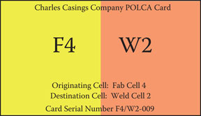
Figure 5.12Detailed design of a POLCA card.
The card also contains detailed explanations of the abbreviations for the cells in case an employee is not familiar with a particular abbreviation. As shown in Figure 5.12, it is also important to put a unique serial number on each card that helps planners keep track of the POLCA cards and—through occasional audits described in Chapter 9—to determine if a card has been misplaced or lost.
Finally, for readers who are familiar with or already using Kanban, you should note that a POLCA card does not have any part numbers, which a Kanban card always has—this results in some of the advantages of POLCA over Kanban for HMLVC products as explained in Chapter 3 and Appendix C.
Decide on the Quantum—The Amount of Work to Be Done per POLCA Card
The next step in your POLCA card design decisions is to determine how much work a POLCA card represents; in a POLCA system this quantity of work is called the quantum and the motivation for it is as follows. A POLCA card returning to an upstream cell signals available capacity at the downstream cell. The question then is, how much work should the upstream cell send to the next cell along with this POLCA card?
The tradeoff involved is that, on the one hand, if the quantum is too large it will result in infrequent and lumpy flow; no work will be sent for a while but then a large amount of work will be sent to the next cell. Both these factors—variability in arrivals of jobs, and large batches—exacerbate queuing effects and waiting times, so this is not desirable. On the other hand, if the quantum is too small, many tiny jobs will flow between the cells and this will require a lot of material handling as well as a large number of POLCA cards in the loop, making it time-consuming to manage and keep track of them. In setting the quantum, you should also take into account the ideal batch sizes you would like to run in the cells. Finally, consider how material is moved between the cells: we will illustrate this with some examples below.
The quantum should be specified in an easy-to-use unit. The simplest quantum is a job (or work order). If jobs usually don’t get too big in terms of their workload, then assigning a POLCA card to each job is the ideal situation and easy to implement because the rule is so clear: “one POLCA card = one job.” Practical examples illustrating this choice are the implementations at the pharmaceutical company Patheon (see Chapter 11) and the custom hinge manufacturer BOSCH Hinges (Chapter 12). Another option is to specify the quantum in terms of work content, such as 20 hours of machining. (An approach recently proposed is to specify the quantum in terms of an innovative concept called Capacity Clusters: this new approach is described in Appendix D.) You can also specify a quantum in pieces. Combining this option with the consideration of your material-handling method can result in a good practical solution. For example, if housings are typically placed on a pallet that is moved by a forklift truck, then the quantum could be the number of housings that will fit on a pallet. This would work well with the material handling process as each pallet could carry a POLCA card attached to it while it is being moved. For a large housing, if only four can be placed on a pallet the quantum becomes four housings, while for a small housing, if nine fit on the pallet then the quantum is nine. The rule for this example is “quantum = one pallet.” Chapter 8 explains why this type of reasoning proved helpful in deciding that “quantum = one cart” at a company making control system cabinets of varying sizes. Companies have used similar rules for other means of material handling to conform to what is typical in their operation. For instance, other rules that have been used are “quantum = one basket” and “quantum = one crate.” Figure 5.13 shows an example of this last option; notice how the POLCA cards are prominently displayed on the material handling crate, and there is space for two POLCA cards since both are needed when the job is in process in a cell.

Figure 5.13Material-handling method of using crates also works as a quantum here. In addition, the crate is being used as a holder of (up to) two POLCA cards.
When the quantum is the same as a job or work order then POLCA works as described in Chapter 2. However, if the quantum is pieces or hours, here’s how the quantum rule is used by the cell team. When a job is Authorized and the right POLCA card is available, if the workload in the job is less than or equal to the quantum, then the job is launched into the cell. If the workload exceeds the quantum, then one of two methods can be used: in the case that the job can be split, then the amount allowed by the quantum is launched into the cell along with one POLCA card. If the job cannot be split, then the team must wait for a sufficient number of POLCA cards of this type to arrive before the job can be launched at all. Let’s go over these two options with an example.
If there are seven housings in a job and the quantum is four, then in the first option, four housings can be started in the cell. The remaining three housings will need to wait for the next POLCA card of the same type to arrive. Now let’s consider the second option. Suppose we are in Cell A, the housings are going on to Cell D next, and the planners don’t want jobs to be split (this could be for quality control or lot integrity reasons). Then the Cell A team needs to have two A/D POLCA cards before it can start work on the housings. Until the two cards are available, the team will need to skip this job just like it did when it was waiting for the one card to show up, and it can work on a job destined for a different cell (any cell other than D) if that job is authorized and has a POLCA card. In particular, it is important to note the qualification in the previous sentence: if there is another authorized job for Cell D that only needs one A/D POLCA card, the team cannot launch this job! Doing this could lead to an ongoing cycle where jobs “steal” A/D cards and the job needing two cards might not get launched for a long time! As part of designing the POLCA system for your operation, you need to decide which of the two options will be used so that the rules are clear for the cell teams.
One other point to note here is with regard to the number of cards in a loop. In a following section, we will go over the calculation of this number. However, keep in mind that if you go with the second option above (that is, that the full set of POLCA cards must be present before the job can be launched), then you should ensure that each POLCA loop has enough cards to accommodate the largest non-split jobs that you expect to release to the shop floor. For example, using the same housings example as above with a quantum of four, if the planner will not release any jobs with more than 20 housings, then you need to have at least five POLCA cards in any loops associated with the routings for the housings. If the calculation below results in a number that is five or more POLCA cards, then this is already accounted for. On the other hand, if the calculation results in less than five cards, then you need to go with five cards. However, if the calculation recommended a much smaller number, such as two cards, you might worry that going with five would often lead to too many jobs in the loop. If the larger jobs are relatively rare, you can go with the recommendation of two cards, and then add a “Safety Card” for the occasional very large jobs. The use of such exceptions is described in the next chapter. Just such a procedure was used by the pharmaceutical company Patheon to deal with occasional large batches that needed to be run all at once (see Chapter 11). A final point to be made here is that if large jobs are relatively rare, you should consider imposing a strict limit on your batch sizes and have your Planning Cell split very large jobs into two separate jobs (work orders). This will also be beneficial to your overall flow as it will reduce the potential for queueing at all cells that are part of this job’s routing.
The quantum doesn’t need to be the same for all POLCA loops. Based on the characteristics of each of the flows, you could have different quantum rules for different parts of your shop floor, as long as this doesn’t cause confusion or too much job-splitting.
Determine the Process for Returning the POLCA Cards
Having decided on which cells will be connected by POLCA loops, as well as the quantum (or quanta, if there are several different ones), you need to design the process that will be used to return POLCA cards from downstream cells to the relevant upstream cells. It may be advantageous to design this procedure in parallel with the decisions on the various quanta, since those decisions will impact the number of POLCA cards that will flow between cells. Also, as mentioned in the previous section, sometimes a particular quantum decision can be based on the material handling method in use for the associated jobs.
Thus, it makes sense to also consider how jobs will be moved from the upstream cell to the downstream cell, because the factors involved actually impact both decisions: moving the job downstream and returning the card upstream.
As a reminder, let’s review the POLCA-related tasks involved in the moving of jobs and cards between cells. When an upstream cell completes a job, that job and the associated POLCA card need to be moved to the downstream cell. When a downstream cell completes a job, the POLCA card which had arrived with that job from the upstream cell needs to be returned to the upstream cell. Note that since many cells will be contained in overlapping loops, for such cells when a job is completed we need to take care of both these tasks. Let’s illustrate this with an example to make it clear. Suppose Cell B is part of an A/B POLCA loop as well as a B/C POLCA loop, and it is currently processing a job that was routed to Cell A, then to Cell B, and next to Cell C. Since the job came from Cell A, it has an A/B card attached to it, and since Cell B is processing this job, through following the Decision Time rules it must have a B/C card also attached to it that allowed Cell B to launch the job into the cell. So, when Cell B completes the job, two tasks must be performed: moving the job along with the B/C card to Cell C; and returning the A/B card to Cell A.
There are many options for how these two tasks can be carried out. The best way to illustrate the choices is to describe various procedures that have been implemented by companies that are using POLCA:
If the two cells in a POLCA loop are closely located and the parts being moved are not too heavy and can be manually moved—for example, in baskets or using light carts—then companies have made it the responsibility of the cell teams to move both the jobs and the cards. So, when a cell completes a job, the cell team is responsible for moving the job and the associated POLCA card to the downstream cell, and the team is also responsible for returning the POLCA card that had arrived from the upstream cell back to the upstream cell. Of course, for the last cell in a POLCA Chain there will be no card to be delivered downstream, and likewise for the first cell in a POLCA Chain there is no upstream cell, so the relevant actions are not needed in those cases.
In the case where your production deals with heavy parts and materials, and jobs are typically moved by specially trained material-handling (MH) operators, both these tasks could be made the responsibility of the MH staff. This could also be the decision in the case where parts are not necessarily heavy, but distances between cells are large and the task of moving jobs is performed by separate MH people, not the cell operators. In this case, completed jobs should be placed in a designated location for each cell; one that is clearly visible to MH operators. Similarly, cards that need to be returned should be put on a board in or near the cell, that is also clearly visible to MH operators. The MH staff should be made aware that the job of returning cards is just as important as moving material; without cards, upstream cells will not be able to start jobs even if they have capacity and the jobs are Authorized, so this will result in unnecessary delays and longer lead times.
At one company that makes large electromechanical products, it was necessary for the jobs to be moved by forklifts operated by specialized MH staff. However, the POLCA implementation team decided that returning the cards would be “everyone’s job.” What this meant was that anyone who walked by a bulletin board and saw POLCA cards that were waiting to be returned could decide, if they were headed in the direction of the upstream cell, to carry the POLCA cards back to that cell. This included managers, supervisors, MH staff, or an operator who happened to be walking through the shop floor for any reason. The company found that there were no problems with this arrangement; on the contrary, it had the benefit that it made everyone feel they were part of the overall POLCA process and cards were returned with minimal delays. The process of returning cards was also made everyone’s job at Patheon, which experienced similar benefits of giving employees a sense of involvement and even ownership of the POLCA implementation (see Chapter 11).
A different way to tackle the issue of returning POLCA cards is to do away with physical cards altogether, and go for an electronic implementation of POLCA. The case study of BOSCH Hinges in Chapter 12 describes why the company decided to go this route and it helped in the development of a “Digital POLCA” system. This system is now in use at several other companies, including Provan (see Chapter 13). Another example of an electronic POLCA system is in Chapter 15. Indeed, these electronic implementations do away with having to manage the physical POLCA cards, and they have also been well received. Electronic POLCA systems also allow the use of a smaller quantum since the number of cards to be managed and returned is not an issue, and a smaller quantum can help smooth out the flow. However, in keeping with the aims of Visual Management, many companies still prefer the visual impact of the physical POLCA cards and POLCA boards, and even though managing the physical cards takes effort, their management believes the benefits are worth this effort. So, at the end of the day, this comes down to a choice by your POLCA Implementation Team as to whether you want to invest in an electronic POLCA system, or if you prefer some of the benefits of using the physical cards. Part III of this book has case studies of companies that chose one or the other of these options; reviewing these case studies will help you with your decision. In fact, some electronic POLCA implementations described in Part III aim to get the best of both worlds by retaining some of the visual benefits through the use of electronic POLCA boards.
As you can expect with physical POLCA cards being handled and moved in a complex shop floor environment, cards will occasionally be misplaced or lost altogether. You need to keep on top of this situation, because missing cards mean that a particular loop has fewer cards than needed, and this will impact your production performance. Chapter 9 will explain the recommended POLCA audit process which assists you in monitoring the availability of POLCA cards.
After you have decided on the POLCA loops, the quanta, the rules for starting jobs, and the procedures for moving jobs and returning the POLCA cards, you should document all these in a flowchart. In addition to being a handy reference for cell teams, this flowchart serves as a valuable tool in the initial training of the cell teams, planners, schedulers, and material handlers as well as any new employees in the future. This will be discussed further in Chapter 7, along with an example of such a flowchart.
Calculate the Initial Number of POLCA Cards in Each Loop
Now that you have decided on the POLCA loops and the quanta, there is a straightforward formula to help you calculate the initial number of POLCA cards you should have in each loop. We deliberately use the term “initial number” because this allocation of cards is expected to change as the system starts working, but as mentioned several times already, it is easy to determine when to add or remove POLCA cards, and equally easy to physically add or remove the cards from any loop. We will discuss this below and also in Chapter 7 in the section on POLCA audits.
We will use an example to explain each of the terms in the formula for the number of cards. Let’s say we are planning a POLCA loop that will go from Cell A to Cell B, in other words an A/B POLCA loop. First, we will need the planned lead times for these two cells. These should already be available since you will be using them to calculate the Authorization Dates (as explained in Chapter 4). Let’s say these lead times are LA for Cell A and LB for Cell B. For this example, we will assume these lead times are in working days, but any units can be used as long as they are consistent with the units used for other items below.
We will also assume that these lead times are internal lead times for the cells and do not include move times. So, next you need to estimate the average time for jobs to be physically moved from Cell A to Cell B. Let’s call this time MovAB. An example for calculating the move time will help you understand the point about using consistent time units. Let’s say that the two cells are not close to each other, and your products are heavy and need to be transported via forklift by special material-handling operators. Based on current operations, you estimate this move will take half a shift on average. Next, say your factory has a two-shift operation. This means that a working day equals two shifts. Suppose the LA and LB values are in working days, and we want to keep MovAB consistent with these units. Then half a shift equals a quarter of a working day, so you will need to use the value MovAB = 0.25.
In a similar fashion, you need to estimate the average time for a POLCA card to be returned from Cell B to Cell A, after Cell B has completed the job attached to that card. You should review the different options for how the card will be returned as explained in the preceding section, and based on your decision, you should estimate the return time. Let’s call this time RetBA; again, you need to be sure it is in consistent units as in the preceding example.
Typically, you calculate your POLCA cards for a planning period such as a month or a quarter. The time horizon for your planning period should be long enough to allow for some aggregate planning through averaging of demand, but at the same time, you should not average widely differing demand periods into one planning period. For example, if there are three months in your planning period, then those months should be expected to be roughly the same on average. On the other hand, if one of those months is expected to have much higher (or lower) demand, then it should be a separate planning period. We will return to this point at the end of this chapter in the section on “Hedging with Lead Time or with Cards?”
To continue the explanation in consistent units as used above, we will stay with working days. Suppose the number of working days in your planning period is D. Now you need to estimate the number of times an A/B POLCA card will flow from A to B during this planning period. Note that this number depends on your choice of quantum: for example, if a particular work order requires two POLCA cards then you need to count this as two cards flowing. The first few rows of Table 5.1 show you how to do this calculation easily, using a situation where the quantum is five housings. Observe from Table 5.1 that this calculation requires that you have rough estimates for the number and types of jobs you can expect during the planning period. Even if you have high variability in demand as well as custom jobs that may also vary, you need these types of estimates for your rough-cut capacity planning anyway, which is a prerequisite for POLCA as explained in Chapter 4. So, based on historical demand and/or input from your salespeople, you should have a process for aggregating jobs into categories even without knowing the details of the actual jobs that will arrive, in order to do your rough-cut capacity planning. That same process will enable you to get the estimates required for Table 5.1. Using the approach in Table 5.1, let’s say you estimate that the total number of times a card will flow from A to B is FlowAB.
Order Size |
Estimated No. of Orders |
No. of POLCA Cards Needed Per Order |
No. of Times a POLCA Card Flows Between the Cells |
|---|---|---|---|
1–5 Housings |
70 |
1 |
70 |
6–10 Housings |
20 |
2 |
40 |
11–15 Housings |
6 |
3 |
18 |
|
FlowAB (Total no. of times a card flows from A to B) |
128 | ||
Additional data:
Planned lead time for Cell A, LA = 3 days
Move time from A to B, MovAB = 0.25 days
Planned lead time for Cell B, LB = 1 day
Return time from B to A, RetBA = 0.25 days
Planning period of one quarter, D = 63 days
Safety margin, S = 0.1
POLCA card calculation using formula in text:
No. of A/B POLCA Cards = (3 + 0.25 + 1 + 0.25) × (128/63) × 1.1 = 10.1
Rounding up to the next integer = 11 A/B POLCA Cards.
The last item that you need for the formula is a choice of safety margin. There are two reasons to include a safety margin for the initial calculation of the number of cards. The first is that the data used to calculate the various quantities in the formula, such as move times or demand numbers, are estimates and we need to allow for a margin of error. The second reason is that the formula is derived using theory based on idealistic average behavior, and in practice the variability and dynamics of the shop floor may require slightly more cards than the formula predicts. (Readers interested in the theory behind the formula can read the technical details in Appendix G.) In practice, from several implementations we have found that a safety margin of 10% along with rounding up the result to the next integer has provided a good starting point for the number of cards in each loop. We will use S to denote the safety margin, expressed as a decimal. Thus, a safety margin of 10% implies that S = 0.1.
You now have all the data you need to calculate the number of A/B POLCA cards—let’s call this number NumAB. The formula for this number of cards is simply:

You can now follow the numerical example in Table 5.1 to see this formula in use, including the rounding off to the next higher integer, to get the value of 11 for the initial number of cards in the A/B POLCA loop.
Once you get your POLCA system operating, you can fine-tune the number of cards based on the actual experiences of the cells. If a cell team complains that it is always waiting for a particular type of card, and there is no obvious problem in the downstream cell, you can consider adding a card to that loop. Conversely, if you frequently see several cards of a given type posted on a cell team’s bulletin board, you can consider taking a card out of that loop. The POLCA audit process described in Chapter 7 will help with these decisions.
Add the Finishing Touches with Some Final Details
We end this chapter with two items that apply across the whole POLCA system. Having thought through all the other elements of the system design, you now have the foundations to finish up with these two final touches:
Thinking through the instances when a Decision Time should occur at a given cell.
Creating a safety valve for extreme variability: whether to hedge with lead time or with cards.
Identify the Triggers for Decision Time
Thus far, we have described what a cell team needs to do when a Decision Time occurs. Specifically, the team’s process was delineated in the Decision Time Flowchart (henceforth “DT Flowchart”) in Figure 2.6, which was explained in Chapter 2. For ease of reference, we reproduce the DT Flowchart here in Figure 5.14. However, we haven’t as yet identified what determines that a particular moment should become a Decision Time. This section recommends the events that should initiate a Decision Time. You can modify or enhance this list to suit your situation.

Figure 5.14Decision Time flowchart.
Let’s start by understanding the motivation for having a trigger for a Decision Time at a particular cell. The aim is to check if the status in the cell has changed in any way that is related to the POLCA system and which would affect the cell’s activities. Looking at the DT Flowchart in Figure 5.14 immediately suggests some examples of status changes that could occur and affect the cell, for instance: a job moves from being Not Authorized to being Authorized; or a job arrives from an upstream cell; or a POLCA card is returned by a downstream cell. Since the cell team members might all be busy and involved with current fabrication or assembly work (and since factories can be noisy environments!) these status changes might not be immediately noticed. So, the first set of triggers is designed to force the cell team to review their POLCA-related status. Hence the following events should trigger a Decision Time for a cell team:
The start of a shift.
Returning from a lunch break or any other mid-shift break or meeting.
If a normal eight-hour shift at your company has a morning and afternoon break along with a lunch break, then just these events alone will ensure that a Decision Time occurs at least once every two hours or so. The next two triggers are based on activities by the team members, so they will know when one of these events occurs and can follow it immediately with a Decision Time:
The team completes a job and delivers it to the next cell.
A team member completes some work and is available to take on new work.
These are the most obvious triggers, but there are other important ones too, as we now elaborate. According to the DT Flowchart, if a cell team cannot launch a job then it goes to Step 4 of the flowchart: “Work on secondary activities based on prepared list, until an event triggers another Decision Time.” The justification for these secondary activities, as well as examples of them—such as cross-training or other improvement tasks—were discussed in Chapter 3. Note that these activities are intended to make use of the time when there are no jobs to be launched, but these activities should not significantly hold up a job if it is available to be launched. So, while the team is engaged in such secondary activities, it needs to be vigilant about whether a job can now be launched. To support this aim, the following additional event should trigger a Decision Time when secondary activities are being conducted:
The team completes a logical phase of a secondary activity (such as, completion of a short cross-training exercise for a given skill). At this stage, it should stop the secondary activity and revisit the Decision Time process to see if a job can be launched.
If your time horizons are short and you are concerned about the time it takes for a cell team to react to a change in status (in other words, jobs might be ready to be launched but the team has not noticed this), then you can consider putting in a signaling mechanism such as a bell, buzzer, or blinking light, that goes off when any of the following events occur:
A job arrives from an upstream cell. (This job might already be Authorized on this cell’s Authorization List, but it is waiting for the material to arrive from upstream—see Step 2 of the DT Flowchart—so it is good for the team to check on this.) The person delivering the job should be instructed to turn on the signal (e.g., one of the items listed above).
A POLCA card arrives from a downstream cell. (There might be an Authorized job waiting for this particular card—see Step 3 of the DT Flowchart.) Similarly, the person returning the card should be instructed to turn on the signal.
A job moves from being Not Authorized to being Authorized. Your IT personnel can program the system that generates the Authorization List to turn on the signal when this happens. (But if you don’t want to get into more dependence on software, or this is too complicated to program, it’s fine, because as we explained above, other events like returning from a break will trigger a Decision Time fairly often.)
If jobs arrive frequently at cells, your shop floor environment operates on short time scales, and you are still concerned that jobs might wait, there is another simple solution: you can set the signal to go off (say) every hour, ensuring that the team will visit the Decision Time logic at least once an hour.
Needless to say, when the signal is turned on, any team member that initiates the resulting Decision Time process should be empowered to turn off the signal. We should also add an alternative perspective here. Some teams may find the signals invasive or disturbing to their work, so it is not necessary for you to use the signaling methods just listed. We mention these ideas here as a possible way to go, but at the same time many of the practical POLCA implementations have worked well without a need for such active signals. The ownership and vigilance of the POLCA-enabled cell teams has been enough to keep jobs moving sufficiently well.
We end this list of triggers with one final item. The following is also an acceptable trigger:
Any other time that a team member elects to go through the Decision Time logic. (This is fine, because it never hurts to go through the Decision Time logic; it can only be helpful.)
As mentioned at the start of this section, above we have listed the recommended triggers for a Decision Time, but you can modify or expand these to suit your particular manufacturing environment.
Hedging with Lead Time or with Cards?
We end this chapter with some mechanisms to mitigate management concerns of POLCA’s ability to operate successfully in a highly variable environment. The POLCA system by its very nature has a certain amount of flexibility as well as ability to adapt and adjust for deviations from the production plan. So, a degree of variability is already accommodated in the combination of planned lead times and card calculations. However, if your company, or certain portions of your operations, experience very high variability, then you need to examine these areas more carefully and consider one of two options to enable POLCA to work effectively. These options are: adding safety through more lead time, or adding safety through more cards. Which way should you go? It turns out that the best option for a company is easy to determine; we will explain the approach in the following sections with examples.
One caveat here. The approach below is not intended for use with seasonal variations. Large variations due to seasonal effects (for example, at a company making snow blowers) should be accommodated through the choice of planning period and corresponding calculation of POLCA cards as explained above. In other words, you should have your planning periods separated into segments with significantly different demand, and calculate the POLCA cards for each of those segments as they occur. The analysis below is for high unanticipated variability that occurs within a planning period. We now discuss the two main options for such situations, and when it is to appropriate to use one or the other.
Adding Safety through Lead Time
If you have a cell that is capacity constrained, and there is no easy way for you to add capacity in the near future, then you have no choice but to go with increasing the planned lead time for that cell. For example, let’s say you have a machining cell with highly specialized and expensive machines, and it is already running two shifts and is still capacity-constrained. In Chapter 4, the section on “Engage in Effective Planning Before Control” explained that companies should aim to have their resources running at no more than 85% utilization on average, for POLCA to be effective. Suppose this cell is already running at 90% utilization—and that’s just on average: some weeks it is running full-tilt at 100% for several days in a row. Although you recognize this is not ideal for POLCA, at this time you do not have the resources to create more capacity. Adding a third shift or weekend shifts would be too expensive or unpopular with the employees, and your company does not have the finances to invest in more machines at the moment. In this case, the only solution for POLCA to work is to add some safety time in the lead time, in other words, the planned lead time for this cell should be increased.
Why will this work? As long as the average utilization of the cell over the planning period is still significantly below 100%, this means that while the cell may be bottlenecked at some points in time, at other points in time it will have capacity to catch up. However, this means that jobs will often wait in queue as the cell goes through the dynamics of being backed up and then working off the backlog. So, this needs to be anticipated in the planning process via a longer lead time for the cell. (This approach also reinforces the logic, now well-recognized in manufacturing system design, that a critical-bottleneck resource should not be starved; this method will indeed put more WIP in front of this bottleneck.)
We should, however, insert a strong caveat here. The mechanism of adding some more lead time, and possibly creating more WIP in front of the bottleneck, is not to be seen as a long-term solution. Worse yet, do not see this approach as a way for you to increase the utilization of all your resources to more than 90%! To meet the goals set for the POLCA system, and to overcome the manifold symptoms listed at the beginning of this chapter, it is essential that you work towards bringing the utilization of this bottleneck more in line with the 85% goal. This might mean adding more capacity, or outsourcing some work, or even rethinking which orders you want to accept; regardless of the solution you choose, do not let the short-term fix make you lose sight of the longer-term goal.
Next, after deciding on the increase in lead time, if you review the formula for calculating the number of POLCA cards, you will see that if you increase the lead time for a cell (in the formula, say LB is increased by 20%), then the number of cards for all loops going to that cell will also increase! Don’t be confused by this, because in this case the driver is the decision to increase the planned lead time, and the change in the number of cards is just the logical result of that decision. The next example will show a different situation.
Adding Safety through Number of Cards
For a cell that has spare capacity, or the ability to create sufficient spare capacity, the approach to deal with high variability should be to stick to the planned lead time, but increase the number of cards by using a higher value for the safety margin (S) in the formula. Again, let’s go over an example, and you’ll also understand what we mean by the ability to create more capacity.
Consider an assembly cell with a team of five people assembling large electromechanical products. The company’s management has a firm belief in the strategy of maintaining spare capacity, so the team’s workload is planned for 80% of capacity. At this company, a normal work week is 40 hours. So, the five-person team has an aggregate of 200 working hours of capacity per week, but with the 80% planning target, their workload averages 160 hours in a week. (As an aside, the management of this company also strongly believes in continuous improvement, so when there are no assembly jobs for the cell, the team works on activities such as cross-training, quality improvement, process improvement, and other tasks, as discussed in Chapters 2 and 3. The company has witnessed substantial productivity gains from these activities over the long term, so there is no concern in upper management about the fact that people are not assembling jobs for 20% of their time.)
This company has instituted several mechanisms to be able to rapidly increase the capacity of any given cell. The first is that just as a baseline, if a cell gets a lot of work, the team can spend the full week doing assembly work and no other activities. This provides an additional 40 hours over the planned capacity of 160 hours—in other words, a 25% increase in capacity without having to do anything out of the ordinary! Next, in a high-demand situation, the team can request the addition of a temporary worker from an agency. True, short-term employees are not trained and skilled up to the level of the cell team. But the team has already analyzed its work and identified a number of simpler jobs that can be handled by a new employee with just a little initial training. Examples of such jobs are cutting insulation foam or picking parts from storage racks. The team has found that it can accommodate and fully utilize one temporary employee without any degradation of quality. This can add up to 40 hours of capacity if needed, or another 25%. As a final option, in an unusually high demand period, management has the option to institute a Saturday shift—an option that has been previously negotiated with the employees. With five people each working an extra eight hours each, this provides an additional 40 hours, or another 25%. If the temporary employee is also included in the Saturday shift, this adds another eight hours, or 5%. Adding up all the possible options, you come to an amazing realization—the management of this company has found a way to quickly increase assembly capacity by a full 80% over its baseline capacity plan!
If maintaining short lead time is strategically important for your company, and if you have cells with spare capacity or the ability for spare capacity, then the best option is to stick with your planned lead times but add more cards. You do this by increasing the value of S in the formula above. For example, instead of the normal choice of 10% of safety margin (S = 1.1) you decide that the team can find ways to handle a surge of work and you choose to go with 40% (S = 1.4).
Again, we can ask, why go this route and why will this work? Let’s say this is a downstream cell for a POLCA loop, and if you start with no safety margin (S = 1.0), the formula gives the number 4.4. If you used the commonly recommended value of S = 1.1, the formula would give 4.8, so you would put five cards in the POLCA loop. If you go with S = 1.4, then the new answer is seven cards (after rounding up to the next integer). Now what will happen is as follows. With its normal planned capacity and lead time, the cell can handle the rate at which jobs arrive when there are five cards in the loop. So, in an “average” week, typically there will be two more cards in the loop than are needed. However, when demand suddenly goes up more than five cards may get used, so more jobs will arrive at the cell, and the cell team will notice that it is getting backlogged. At this time, the team can kick into high gear and start adopting some of the capacity increasing strategies. For example, it could begin by just eliminating improvement activities and adding the first 40 hours of weekly capacity. If jobs continue to arrive at a fast pace and the cell is still backlogged, it can go on to some of the other strategies listed above. The main point is that by using its spare capacity, the cell can get jobs completed without lengthening its lead time. Similarly, upstream cells can continue to send jobs without being temporarily shut down due to lack of cards, again avoiding the addition of any lead time.
Note that POLCA acts as an effective signaling system to tell the team when it needs to kick in these additional strategies, as well as for management to see and approve, for example, a request for a temporary worker. Suppose there is a surge in demand and jobs are scheduled for the assembly cell at a higher than normal rate. Then all seven POLCA cards will get used as described above, and the cell team will notice that it is backlogged. It will also notice that no sooner that it finishes a job and sends a card back upstream, another job arrives with that card! If this continues for a couple of days, and the team looks into the schedule and sees that there is no let up for at least another week or more, it can decide which of the capacity strategies it wants to implement. Conversely, when the surge subsides and the team has caught up, there will be unused POLCA cards in the upstream cell and fewer than seven jobs at the assembly cell. If this also continues for a couple of days, the team can decide that it no longer needs the spare capacity.
This completes the description of the major aspects of the design of your POLCA system. Realizing that, in the real world, there will occasionally be some exceptional situations that arise, the next chapter will show you how to deal with such exceptions while still staying within the POLCA system rules.