
Steam Generators
A steam generator or a boiler is that part of a steam power plant in which steam is generated to produce electrical power and/or to get used in an industrial process. A steam generator comprises two important parts, i.e., a furnace, where a fuel is burnt to generate heat, and a proper boiler, where this generated heat is used to convert water into steam. Heat energy contained in flue gas is exchanged in a superheater, reheater, economizer, air heater, etc. After passing though the economizer the feedwater enters either the boiler drum for circulation in a sub-critical boiler or a steam separator in a supercritical boiler. Steam coming out of the drum/separator is further passed through the superheater and reheater to elevate the temperature of steam. Insulation is applied on boiler casing to mitigate loss of heat to surroundings.
Keywords
boiling; DNB; circulation; design; furnace; fuel burning equipment; utilization; mounting; insulation; superheater; reheater; economizer; air heater; supercritical
2.1 Introduction
Man has used the technique of converting water (liquid) into steam (vapor) and using the expansive force of this vapor as far back as 150 B.C. Yet it took human beings more than 1800 years to harness the practical qualities of steam to do useful work. It was around the year 1711 that the first commercial piston-operated mine pump was invented [1], but it wasn’t until the latter half of the nineteenth century that the first steam-operated central power station was introduced. It was in the year 1882 that Holborn Viaduct power station in London and Pearl Street Station in New York had been put into service using reciprocating steam engines.
The main objective of a steam power station is to generate electrical power. In a steam power station, the electrical energy is produced according to the principle of “external combustion,” where the “heat of combustion” of the fuel is transferred to a prime mover by a “working medium.” In the steam generator, low-temperature water is the working medium that receives the heat of combustion of fuel and becomes high-energy steam. The heat of steam is converted to mechanical energy in the steam turbine and then to electrical energy in the generator. The sequence of these activities is shown in Figure 2.1.

The chemical energy available in fossil fuel (i.e., coal, fuel oil, gas) is converted to heat energy by combustion in a steam generator. The heat thus liberated is absorbed by continuously feeding water in a combination of heat-transfer surfaces, resulting in a continuous generation of steam. The water fed into a steam generator is called feedwater. Steam and feedwater together is called working fluid. The name “steam generator” is also still called “boiler,” but modern steam generators in the supercritical class do not involve the “boiling” phenomenon.
The fuel-firing equipment of a steam generator should completely burn the fuel used in the furnace to release as much energy as possible. Air is fed into the furnace for combustion of fuel-forming products of combustion or flue gas. The heat released by burning fuel is absorbed in different heat-transfer surfaces to the maximum level possible practically and economically to keep the loss of heat to a minimum. In the heating surfaces, the flue gas transfers its heat to the working fluid. Thus, the feedwater is pre-heated to the saturation temperature and vaporized. The saturated steam thus formed is further superheated. After passing over the heating surfaces at various zones the flue gas is cooled and discharged to the atmosphere through a stack.
The primary function of a steam generator is to generate steam under pressure, but modern steam generators are also required to do the following:
i. Ensure generation of exceptionally high-purity steam by eliminating all impurities from saturated steam.
ii. Raise the degree of superheat of supplied steam as specified and maintain the same temperature over a defined range of load.
iii. In large power stations after partial expansion in the turbine steam is returned to the steam generator for further superheating and then transmitted to the turbine for complete expansion. This new degree of superheat is called “reheat” and should also be maintained constant over a defined range of load.
iv. While executing the above duties, a steam generator must utilize the heat of combustion of fuel as efficiently as possible.
2.2 Boiling and Circulation
Boiling of a liquid refers to a condition where vapor bubbles form on the heating surface of the liquid. Formation of bubbles depends on the fluid properties and the operating and surface conditions. When heat is added to a liquid, its temperature does not increase beyond its saturation temperature corresponding to its pressure, instead, the energy used results in a change of phase from a liquid to a gaseous state, e.g., from water to steam. This process, which takes place at constant pressure and constant temperature, is known as boiling.
The boiling point of a liquid is defined as the temperature at which its vapor pressure is equal to the pressure of the gas above it. This temperature is also called saturation temperature. In an open vessel the boiling point of a liquid refers to a temperature at which its vapor pressure is equal to the external pressure at one atmosphere. In the event that the external pressure becomes less than one atmosphere, the boiling point of the liquid gets reduced. As the external pressure rises above one atmosphere, the boiling point of the liquid also starts rising. Figure 2.2 shows the boiling point of water as a function of the external pressure. Note the boiling temperature of 373 K corresponds to a pressure of 101.3 kPa and temperature of 473 K to a pressure of 1554.0 kPa.

Boiling occurs when heat is added to the liquid at such a rate that its temperature is at least equal to its saturation temperature corresponding to the total pressure over the free surface of the liquid. If the vessel is open to atmosphere, the vapor displaces the air from its surface of the liquid entirely, whereas with evaporation the vapor is removed by diffusion. The heat, which changes water to steam, is called the heat of evaporation or heat of vaporization.
The heat transfer that takes place from the wall to the liquid during boiling is given by the convective heat transfer equation:
(2.1)
h: Heat transfer coefficient, W/m2K
A: Area across which heat flow takes place, m2
ΔT: Difference in temperature between the heating surface and the temperature of the fluid, K
The “heat flux” at the heating surface is found from Eq. 2.1 as:
(2.2)
2.2.1 Pool boiling
When a large volume of liquid is heated by a submerged heating surface and the motion is caused by free convection currents stimulated by agitation of the rising vapor bubbles, it is called pool boiling [2]. During the course of heating it is noted that a general correlation lies between the gradually increasing heat flux, q, from the immersion heater and the corresponding temperature difference between the surface of the heater and the bulk of liquid, ΔT. The result of such correlation is presented in Figure 2.3 [1].

At point A since the heat flux is very low, no boiling occurs and no bubbles are formed, hence movement of liquid is by natural convection. In the region A-B, phase change takes place only as evaporation at the free surface of liquid that is at the liquid-vapor interface, and the corresponding heat flux is proportional to ΔT4/3 [2].
A further increase in heat flux will result in vapor bubble formation at the hot surface, yet the bulk of the liquid may still be below saturation temperature. The bubbles, which form in the hot boundary layer, condense as they rise into the colder liquid, giving up their latent heat to raise the temperature of the water. This phase change still occurs because of evaporation at the free surface. Bubble agitation in this region, B-C, is insignificant, since there is only a minor change in the slope of the curve. The formation and release of the steam bubbles at the metal water interface, with water still wetting the surface, cause ΔT to remain low. This region, wherein heat transfer takes place by natural convection, is called subcooled nucleate boiling [3].
Further rising of heat flux results in rapid formation of a large number of bubbles on the hot surface. As a result, strong local velocity is encountered within the liquid, causing a further increase in heat transfer. This is the region of nucleate boiling, where the bulk of the fluid is at saturation temperature and bubbles travel through bulk of the liquid to emerge at the free surface. Beyond point C bubbles do not collapse. This region, C-D, is one of stable boiling, and has a very steep slope. The heat flux is proportional to ΔTm, where “m” lies between 2 and 4 [3]. In this region, as the surface temperature is increased, the heat flux also increases up to a maximum value at point D.
Nucleate boiling is incipient boiling, which is characterized by the growth of bubbles on the heated surface that rise from discrete points on a surface, whose temperature is only slightly above the liquid’s saturation temperature. In general, the number of nucleation sites is increased by an increase in surface temperature. An irregular surface of the boiling vessel (i.e., increased surface roughness) can create additional nucleation sites, while an exceptionally smooth surface, such as glass, lends itself to superheating. Under these conditions, a heated liquid may experience boiling delay and the temperature may go somewhat above the boiling point and fail to boil.
Beyond the nucleate boiling region, the bubbles of the steam forming on the hot surface begin to interfere with the flow of water to the surface and eventually coalesce to form a film of superheated steam over part or all of the heating surface. This thin layer or film of vapor has low thermal conductivity and thus insulates the surface and reduces heat transfer and the heat flux, which in turn results in higher metal temperature. When vapor film insulates the surface from the liquid it is called film boiling. Region D-E shows the “onset of film boiling.” At point E bubbles become so large and numerous that liquid has difficulty approaching the surface as the bubbles rise and thus starve the surface of liquid. Consequently there is a sudden jump in heating surface temperature, as shown at point E′. With water at atmospheric pressure, ΔT might be 25K at E and more than 1000K at E′ [2]. At this temperature there is a real danger of heating surface burning out or melting. Hence, point E is known as the burn out point. It is therefore imperative to operate as close as possible to point E that is at point D, without the risk of burn-out. If at point E a situation arises when heat flux would be dependent on the surface temperature, as when a fluid is condensing at variable pressure, it will be possible to reach point F from point E.
Region E-F in Figure 2.3 shows unstable film boiling where the vapor blanket alternately breaks down and recovers. As a result there is a decline in heat flux with increase in surface temperature.
Beyond point F, in the region F-G, the vapor film becomes thicker and film boiling becomes stable, where heat flux again increases with an increase in ΔT. Heat is transferred by conduction, convection and radiation across the layer of vapor that blankets the heating surface. At this region only evaporation takes place without formation of any bubble. This region thus is identified as stable film boiling one. If now the heat flux is reduced below the value at point G, the conditions do not jump back to E, but follow a path to point F. At this point the vapor film suddenly collapses and conditions revert to those at point H on the nucleate boiling curve.
Point D, which is very close to point E, is known as the point of departure from nucleate boiling (DNB) or the “critical heat flux.” Heat flux at D is extremely high, as for example with water at atmospheric pressure heat flux is about 1500 kW/m2 [2]. The temperature difference, ΔT, between the boiling liquid and the heating surface at which the critical heat flux occurs, is known as the critical temperature difference.
During operation of the boiler it is difficult to theoretically predict the heat transfer coefficients of nucleate boiling that would ensure ΔT remains below the critical temperature difference. Nevertheless, the ability to predict the value of the maximum heat flux, qmax, i.e., point E in Figure 2.3, is also useful as this represents an upper limit in the nucleate boiling heat transfer. The following formula, from Roshenow and Griffith, gives the value of qmax in SI units, i.e., W/m2 [3].
(2.3)
Once the critical heat flux data is determined it is compared with the required heat flux data. For the design to be acceptable, the critical heat flux, which is dependent on the following parameters, must always be greater than the heat flux generated in the course of boiling.
2.2.2 Forced-convection boiling
Besides pool boiling, vapor is also generated by passing liquid through a tube heated either by firing fuel, as in a once-through boiler, or by condensing steam, as is commonly used in process industries. This method of generating vapor is known as forced-convection boiling.
The nature of boiling in forced convection is similar to pool boiling in many ways like the regimes of nucleate or film boiling. The most important difference is in the cause of “burn-out,” since the vapor and liquid must travel simultaneously through the tube. As a result both heat transfer and pressure drop are affected by the behavior of the two-phase flow, which keeps on changing along the tube due to gradual evaporation of liquid. In a once-through tube, liquid below or at the saturation point enters at the bottom and gradually evaporates until a dry or superheated vapor leaves at the top. In the process, some or all of the following regions are encountered by the flow system (Figure 2.4):
1. A liquid heating region or a subcooled boiling region: in this region bubbles are formed at the tube surface but subsequently collapse within the liquid. The heat transfer to the liquid will be by natural convection.
2. A saturated nucleate boiling region: where forced convection dominates. This is the region in which the local tube surface temperature is sufficiently superheated corresponding to the local pressure, causing bubbles to form at the surface.
3. An annular region: where the vapor travels along the tube as a continuous stream carrying with it some droplets of liquid, while the remaining liquid flows as a thin film. Heat transfer in this region takes place by conduction and forced convection. Following the annular region tube surface no longer remains wetted resulting in sudden jump in wall temperature; eventually ‘dry out’ condition or ‘critical heat flux’ is arrived at.
4. A region of pure vapor: in this region heat transfer takes place by natural convection.

The first and the fourth regions are extremes consisting of liquid only and vapor only regions, respectively. In these regions in turbulent flow the phenomena of heat transfer to water and to superheated steam in pipes is described by the Dittus-Boelter equation as follows [3].
For turbulent flow through tubes the phenomenon of heat transfer to water is described by
(2.4)
For superheated steam through pipes, the equation is
(2.5)
h: Convective heat transfer coefficient, W/m2K
d: Internal diameter of pipe, m
μ: Dynamic viscosity of fluid, kg/m.s
From Eq. 2.4, the heat transfer coefficient of water is found as
(2.6)
From Eq. 2.5, the heat transfer coefficient of superheated steam is
(2.7)
Tf: Absolute temperature of bulk water, K
Tg: Absolute temperature of superheated steam, K
Vf: Velocity of water through tube, m/s
Vg: Velocity of superheated steam through tube, m/s
Example 2.1
In a once-through boiler, feedwater enters through the bottom of tubes, receives heat from combustion of coal, and escapes from the top of the tubes as superheated steam. Calculate the heat transfer coefficients of water and superheated steam using the following data:
Pressure of feedwater at tube inlet=27.0 MPa
Absolute temperature of feedwater, Tf=563 K
Pressure of superheated steam at tube outlet=24.5 MPa
Absolute Temperature of superheated steam, Tg=838 K
Velocity of Feedwater through each tube, Vf=6 m/s
Solution: The density of feedwater at 27.0 MPa and 563 K is
The density of superheated steam at 24.5 MPa and 838 K is
For constant mass flow through each tube,
Hence, the velocity of superheated steam through each tube is
Applying Eq. 2.6, the heat transfer coefficient of water is
Applying Eq. 2.7, the heat transfer coefficient of superheated steam is
2.2.3 DNB (departure from nucleate boiling)
At the onset of boiling, metal temperature remains marginally above the saturation temperature of fluid. This is accomplished by maintaining adequate supply of liquid to avoid the occurrence of DNB. As heating continues, the liquid phase changes to vapor and the DNB point (point D in Figure 2.3) is reached, which is also the end point of the nucleate boiling. The metal temperature starts increasing at this point until point E is reached. In the region E-F, the metal temperature decreases, but increases again in the superheat region beyond point F. In the event the applied heat flux exceeds the critical heat flux, which is a function of pressure, the DNB would occur at low steam quality causing the metal temperature to be high enough to melt the tube.
In an optimistic design, in most boilers, ΔT is of the order of 3–6 K, which is well below the critical temperature difference of water at point E, i.e., about 25 K at atmospheric pressure. Thus ensuring the design value of heat flux is much lower than the maximum value or the critical heat flux.
2.2.4 Circulation
In drum-type subcritical boilers, water flows from the drum through downcomers to the bottom of the furnace, then moves up through risers or evaporator tubes and returns to the drum. From Figure 2.5 it can be seen that the water in the downcomers does not receive any heat while risers, which form furnace walls, absorb the heat of combustion of the fuel. As a result, the water inside the riser tubes is heated and gradually steam bubbles form in the water. This mixture of water and steam in the riser tubes has a much lower density than the density of water alone in the downcomers. A density difference thus generated results in a static head difference causing thermo-siphon effect, which provides the driving force for a downward flow in downcomers and an upward flow in risers. Since the flow of fluid is generated by density difference alone, this is known as natural circulation in boilers [1,4,5].

For maintaining continuous circulation of fluid, the fluid flow must overcome friction losses in downcomer and riser tubes, headers, bends, etc. One way of overcoming resistance due to friction is by increasing heat input to the furnace. As the heat absorption increases the density difference between the fluid in the downcomers and the fluid in the risers also increases, resulting in an increase in fluid flow. However, an increase in fluid flow in turn also causes an increase in friction loss. As a result, a point is reached when the rate of increase in friction loss surpasses the benefit of the enhanced density difference, where the rate of fluid flow starts to “drop.” Hence, all natural circulation boilers are designed to operate below the point of “drop.” The phenomenon of rising flow-rising heat input tends to make a natural circulation boiler self-compensating in the case of sudden overloads, changes in heat-absorbing surface condition, non-uniform burner disposition, etc.
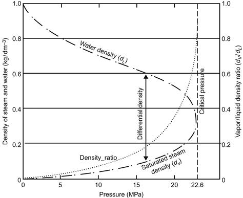
As the operating pressure of fluid is increased, the density difference between the saturated liquid and the saturated vapor starts diminishing and reduces to zero at critical pressure, as is evident from Figure 2.6. Thus it becomes imperative to raise the height of the boiler higher to maintain adequate circulation with higher-pressure boilers.
In practice, at 18 MPa or higher fluid pressure the density difference is so small that it is difficult to maintain natural circulation, even after substantially increasing the height of the boiler. In such cases the fluid flow in the boiler tubes is ensured with the help of assisted or forced circulation.
In assisted or forced circulation, pumps are incorporated in the downcomer circuit to help natural circulation overcome friction losses. Downcomer tubes from the boiler drum are connected to a common header that serves as the suction header of the pumps. Discharge piping of these pumps is then connected to another header from which riser tubes are issued. Since forced circulation can overcome higher-resistance circuits smaller diameter riser tubes, than the tube diameter of natural circulation boilers, are used to economize the cost of tube materials. To reap the economic benefits of assisted circulation, this type of circulation is also adopted in some boilers operating at a pressure below 18 MPa.
The process of circulation, be it natural or forced, is dominated by what is called the circulation ratio, which is defined as the ratio of the “quantity of water in circulation” to the “quantity of steam produced.” For a natural circulation boiler (up to 18 MPa) the circulation ratio may range from 4 to 30, while for forced circulation boiler the circulation ratio varies from 3 to 10 [6].
2.3 Design
As discussed earlier, the chemical energy in fuel is converted to heat energy by combustion, and low-temperature water in the steam generator receives this heat of combustion and becomes high-energy steam for use in the steam turbine. The salient features of this heat-transfer process encompasses the following circuits, systems, and/or areas:
2.3.1 Water and steam circuit
At operating pressure, temperature of the feedwater, prior to entering the steam generator, is less than that at the saturated condition, i.e., the entering feedwater is under the subcooled condition. Within the steam generator, the feedwater temperature is elevated to the near-saturation temperature in the economizer. Thereafter, the sensible heat for bringing the feedwater to saturation and the latent heat for evaporation of saturated feedwater is added in the water-wall for generating steam. This steam is separated from the steam-water mixture coming out from the water-wall and purified in the boiler drum to ensure the supply of saturated steam. The saturated steam is further superheated to attain the desired energy level.
The heat-transfer surfaces discussed so far, e.g., economizer, water-wall, superheaters/reheaters, etc., are located in the steam generator in the flow path of products of combustion so that heat is absorbed efficiently in proper proportions in various heat transfer zones.
The evaporation zones are comprised of the boiler drum, downcomers, and riser tubes or simply risers. While the boiler drum and downcomers are located outside the heat transfer zone, the riser tubes are exposed to heat transfer. While flowing through the riser tubes the feedwater receives the heat of combustion for evaporation. The riser tubes in modern steam generators are arranged such that they form the enclosure of the combustion chamber or furnace and receive the heat. Hence, riser tubes are usually called water-walls.
The feedwater from the economizer enters the boiler drum, flows down through the downcomers, passes through the pipes to the water-wall bottom header and rises through the riser tubes. In the riser tubes, the feedwater absorbs the heat, part of which is converted to steam and re-enters the boiler drum as a steam-water mixture. From this mixture, steam is separated in the boiler drum and purified. Dry saturated steam from the boiler drum is lead out through the saturated steam pipes to the superheaters. The complete flow path of working fluid is shown in Figure 2.7.

The process of separation and purification of steam in the boiler drum is accomplished by drum internals, e.g., cyclones, baffles, etc., chemical and feedwater admission piping, blow-down lines, etc. (Figure 2.8). The process includes three steps: separation, steam washing, and scrubbing.

Separation is the process of removing the bulk mass of water from steam and is accomplished by any one of following means:
Steam washing, scrubbing, or steam drying is the process of passing steam between closely fitted corrugated plates or screens on which mists are deposited in a way similar to that occurs during filtration. To avoid re-entrainment of water, velocity is kept low. The collected water drips to the boiler water below by gravity.
The arrangement of drum internals must be such as to ensure the following [1,3]:
i. Provide high-purity steam to prevent salt deposition in superheaters
ii. Provide steam-free water to the downcomers for maximum circulation
iii. Assure minimum pressure drop through the separators
iv. Provide simple design and easy accessibility for drum inspection
The function of the superheaters and reheaters is to raise the total heat content of the steam. There are two fundamental advantages of providing superheaters and reheaters: first, gain in efficiency of the thermodynamic cycle and second, enhancement of life in the last stage of the turbine by reduction of moisture content of the flowing steam.
In low-temperature boilers only convection superheaters are used, but large, high-temperature steam generators use both radiant and convection superheaters along with the reheaters to achieve the required superheat and reheat final steam temperatures. Today, modern steam power plants run at lower load at rated conditions during off-peak hours. Hence, the superheater/reheater elements are designed to achieve a normal operating temperature at about 60% of the boiler maximum continuous rating (BMCR) load for better steam turbine performance. The location of superheaters and reheaters in the flue-gas path are normally split into primary and secondary sections to facilitate reasonably unchanged steam temperature control.
2.3.2 Furnace
In the furnace of a steam generator combustion of fuel takes place with atmospheric air to release heat. Hence, it is essential to ensure complete combustion of fuel under all operating conditions to harness the maximum heat potential of the fuel under combustion. (Detailed treatment of this process is included in Chapter 3, Fuels and Combustion.)
2.3.3 Fuel-burning system
The primary function of a fuel-burning system is to provide controlled and efficient conversion of chemical energy of the fossil fuel into heat energy. The heat energy thus generated is transferred to the heat-adsorbing surfaces of the steam generator. The main equipment for firing fossil fuel in a furnace is the burner.
An ideal fuel-burning system in a furnace is characterized by the following:
a. No excess oxygen or unburned fuel in the product of combustion
b. Low rate of auxiliary ignition energy input to initiate and sustain continuity of combustion reaction
c. Wide and stable firing range
d. Fast response to demand for a change in firing rate
e. Uniform distribution of flue-gas weight and temperature in relation to parallel circuits of heat-absorbing surface
f. High degree of equipment availability with low maintenance requirement
g. Safety must be the main requirement under all operating conditions
2.3.4 Draft system
For sustaining a healthy combustion process in a furnace it needs to receive a steady flow of air and at the same time remove products of combustion from the furnace without any interruption. When only a chimney is used for the release of products of combustion, the system is called a natural draft system. When the chimney is augmented with forced draft (FD) fans and/or induced draft (ID) fans the system is called a mechanical draft system. Small steam generators use natural draft, while large steam generators need mechanical draft to move large volumes of air and gas against flow resistance. A furnace utilizing an FD fan only is subjected to “positive draft” (pressurized), while one using an ID fan only is subjected to “negative draft” (subatmospheric pressure). Normally large coal-fired steam generators utilize balanced draft, employing both FD fans and ID fans. Figure 2.9 presents the flow path of a typical balanced draft furnace.

2.3.5 Heat recovery system
The flue gas or products of combustion leaving the convection heat-adsorbing surfaces in large steam generators still carry considerable heat energy at a temperature much above the steam saturation temperature. This heat, if exhausted to atmosphere without further heat transfer, will result in considerable losses. As a natural consequence of economic operation of a steam generator, a major part of this heat is recovered by placing the economizer thereafter the air heater in the exit flue-gas path.
Theoretically it is possible to reduce the flue-gas temperature to that of the incoming air to the air heater, but for technical and economic considerations, as described below, such reduction in exit flue-gas temperature is prohibited.
i. All fossil fuels are sulfur-bearing fuels. As such, if the exit flue-gas temperature from the air heater falls below the acid dew point of the as-fired fuel, sulfurous or sulfuric acid will form, causing back-end corrosion in the air heater. As a consequence, both maintenance cost and plant outages will increase.
ii. Capital costs incurred for installing additional heat recovery surfaces may offset the savings obtained by reducing flue-gas temperature.
In an economizer the incoming feedwater absorbs heat from the exiting flue gases, raising the temperature of the feedwater as close as possible but lower than its saturation temperature prior to entering into the evaporating circuit.
The remaining heat in flue gas downstream of the economizer is recovered in air heater to raise the temperature of combustion air before it enters the furnace. The energy thus recovered returns to the furnace and reduces the amount of heat that must be released by the fuel to maintain the desired furnace temperature, thereby ensuring reduction in the amount of fuel to be burned. The hot air is also used to dry coal in a pulverized coal-fired boiler.
2.4 Classification and Utilization
The function of a steam generator is to provide controlled release of heat in the fuel and to transfer this heat safely, reliably, and efficiently to the feedwater and steam. In a boiler no work is done on or by the fluid as it passes through the system. Hence, based on its use, location of fire and water spaces, type of circulation, arrangement of steam and water spaces, etc., steam generators are classified as follows [7]:
a. As per location of fire and water spaces –
• Forced/Assisted Circulation Boiler
c. Based on pressure requirement –
d. As per arrangement of steam and water spaces –
e. Based on type of firing/heat transfer –
Although boilers are classified in various categories, in practice all boilers fall into two or all of the above categories. Hence, selection of the type and size of boiler depends on the following factors:
• Required quantity of steam to be generated
• Boiler outlet steam pressure and temperature to be maintained
• Economy of steam/power generation
2.4.1 Fire-tube boiler
In this type of boiler hot gases pass through the tubes and water is contained in the shell. As the name suggests, its general construction is as a tank of water perforated by tubes that carry hot flue gases from the fire. The tank is usually cylindrical in shape to realize the maximum strength from simple structural geometry. The tank may be installed either horizontally or vertically.
Typically the furnace and the grate, on which fuel is burnt, are located underneath the front end of the shell (Figure 2.10). The gases pass horizontally to the rear, then either release through the stack at the rear or reverse directions and pass through the horizontal tubes to stack at the front. The fire tubes can be placed horizontally or vertically or at an inclined plane in a furnace.

In this type of boiler boiling takes place in the same compartment where water is stored. As a result, only saturated steam used to be produced in older designs of this type of boiler, but today, a fire-tube boiler may generate superheated steam as well.
A fire-tube boiler is sometimes called a “smoke-tube boiler” or “shell boiler.” This type of boiler was used on virtually all steam locomotives in horizontal “locomotive” form. It has a cylindrical barrel containing the fire tubes, but also has an extension at one end to house the “firebox.” This firebox has an open base to provide a large grate area and often extends beyond the cylindrical barrel to form a rectangular or tapered enclosure.
Fire-tube boilers are also typical of early marine applications and small vessels. Today, they are used extensively in the stationary engineering field, typically for low-pressure steam use such as for heating a building. However, the steam-generating capacity and outlet-steam pressure of these boilers are limited, therefore, they are unable to meet the needs of larger units. Another disadvantage of these boilers is that they are susceptible to explosions.
2.4.2 Water-Tube Boiler (Figure 2.11)
To generate high evaporation rate accompanied by high steam pressure, the fire-tube boiler becomes exorbitantly heavy; therefore, the size and weight become extremely difficult to manage. In regards to the size of the shell, these shortcomings are circumvented by passing flue gases outside the tubes, instead of inside, and water is circulated through the tubes for evaporation. Baffles are installed across the tubes to allow cross flow of flue gases to ensure maximum exposure of the tubes. On the basis of configuration of tubes inside the furnace, this boiler is further classified as “straight-tube boiler” and “bent-tube boiler.”

In a water-tube boiler water circulates in tubes heated externally by the hot flue gas. Fuel is burned inside the furnace, creating hot gas that heats up the water in the steam-generating tubes. Cool water at the bottom of the steam drum returns to the feedwater drum of small boilers via large-bore “downcomer tubes,” where it helps pre-heat the feedwater supply. In large utility boilers, feedwater is supplied to the steam drum and the downcomers supply water to the bottom of the water-walls. The heated water then rises into the steam drum. Here, saturated steam is drawn off the top of the drum. In large utility boilers water-filled tubes form the walls of the furnace to generate steam and saturated steam coming out of the boiler drum re-enter the furnace through a superheater to become superheated. The superheated steam is used in driving turbines.
2.4.3 Natural circulation boiler
Boilers in which motion of the working fluid in the evaporator is caused by thermo-siphon effect on heating the tubes are called “natural circulation boilers.” As discussed in section 2.2 circulation of water in natural circulation boilers depends on the difference between the density of a descending body of relatively cool and steam-free water and an ascending mixture of hot water and steam. The difference in density occurs because the water expands as it is heated, and thus, becomes less dense. All natural circulation boilers are drum-type boilers.
2.4.4 Forced/assisted circulation boiler
As noted in section 2.2 the density difference between the saturated liquid and saturated vapor starts diminishing at 18 MPa or higher fluid pressure, thus it is difficult to maintain natural circulation of fluid flow in boiler tubes. In such cases fluid flow is ensured with the help of forced/assisted circulation using pumps. The forced/assisted circulation principle applies equally in both supercritical and subcritical ranges.
2.4.5 Subcritical boiler and supercritical boiler
The critical pressure is the vapor pressure of a fluid at the critical temperature above which distinct liquid and gas phases do not exist. As the critical temperature is approached, the properties of the gas and liquid phases become the same, resulting in only one phase. The point at which the critical temperature and critical pressure is met is called the critical point. The critical pressure and critical temperature of water and steam are 22.12 MPa and 647.14 K, respectively. Any boiler that operates below the critical point is called a subcritical boiler, and one that operates above the critical point is known as a supercritical boiler. (Supercritical boilers are covered in section 2.10.)
2.4.6 Drum-type boiler
In a drum-type boiler the drum acts as a reservoir for the working fluid. These boilers have one or more water drums, depending on the size and steam-generating capacity. The drum is connected to cold downcomers and hot riser tubes through which circulation of working media takes place. The lower portion of the drum with feedwater is called the water space and the upper portion of the drum occupied by steam is called the steam space. A drum-type boiler can be either the natural circulation type or forced/assisted circulation type. Drum-type boilers are essentially subcritical boilers; they operate below the critical pressure of the working fluid. The economic design pressure limit of fluid in a drum-type boiler is around 18 MPa.
2.4.7 Once-through boiler
This type of boiler does not have a drum. Simply put, a once-through boiler is merely a length of tube through which water is pumped, heat is applied, and the water is converted into steam. In actual practice, the single tube is replaced by numerous small tubes arranged to provide effective heat transfer, similar to the arrangement in a drum-type boiler. The fundamental difference lies in the heat-absorbing circuit. Feedwater in this type of boiler enters the bottom of each tube and discharges as steam from the top of the tube. The working fluid passes through each tube only once and water is continuously converted to steam. As a result there is no distinct boundary between the economizing, evaporating, and superheating zones. The circulation ratio of this type boiler is unity [6]. These boilers can be operated either at subcritical or at supercritical pressures.
2.4.8 Stoker-fired boiler
Prior to the commercial use of “fluidized-bed boilers” (Chapter 5), stoker-fired boilers provided the most economical method for burning coal in almost all industrial boilers rated less than 28 kg/s (100 tph) of steam. This type of boiler was capable of burning a wide range of coals, from bituminous to lignite, as well as byproducts of waste fuels. However, over the years this type of boiler has become less popular due to more efficient technological advancement.
In stoker-fired boilers coal is pushed, dropped, or thrown on to a grate to form a fuel-bed. Stokers are divided into two general classes: overfeed, in which fuel is fed from above, and underfeed, wherein fuel is fed from below. Under the active fuel-bed there is a layer of fuel ash, which along with air flow through the grate keeps metal parts at allowable operating temperatures. Figure 2.12 and Figure 2.13 show a chain-grate overfeed stoker and a traveling grate overfeed stoker, respectively.


A comparison of the traveling grate stoker and the spreader stoker is given in Table 2.1.
Table 2.1
Comparison of ‘traveling grate stoker’ and ‘spreader stoker’

2.4.9 Fossil fuel-fired boiler
Coal, fuel oil, and natural gas are the main types of fossil fuel [8]. These fuels can generate a substantial quantity of heat by reacting with oxygen. These fuels consist of a large number of complex compounds comprised of five principal elements: carbon (C), hydrogen (H), oxygen (O), sulfur (S), and nitrogen (N). Any of these three fuels, i.e., coal, fuel oil, and natural gas, can be used in steam power stations, but coal plays a large role in power generation because of the enormous reserves of coal in many countries around the world, e.g., the United States, China, Mongolia, India, Indonesia, Russia, Poland, South Africa, Australia, etc. Most of the large steam-generating stations in these countries are coal based, and coal is expected to remain a dominant fuel for this purpose for many years. Coal-fired power plants at present account for about 41% of power produced globally [9].
Coal-based steam-generating stations also dominate in those countries where natural gas and fuel oil are abundantly available, since the cost of natural gas and fuel oil is exorbitantly high compared to the cost of coal. Additionally, natural gas and fuel oil are more economical in other industries. In modern, large-capacity, coal-fired steam generators coal is burnt in suspension. (Pulverized coal-fired boilers are covered in more depth in Chapter 4.)
2.4.10 Fluidized-bed boiler
Fluidized-bed combustion ensures burning of solid fuel in suspension, in a hot inert solid-bed material of sand, limestone, refractory, or ash, with high heat transfer to the furnace and low combustion temperatures (1075–1225 K). The combustor-bed material consists of only 3–5% coal. Fluidized-bed combustion is comprised of a mixture of particles suspended in an upwardly flowing gas stream, the combination of which exhibits fluid-like properties.
Fluidized-bed combustors are capable of firing a wide range of solid fuels with varying heating value, ash content, and moisture content. In this type of boiler, pollutants in products of combustion are reduced concurrently with combustion – much of the ash and hence the particulate matter as well as sulfur is removed during the combustion process. Further, lower temperature combustion in the fluidized bed results in lower production of NOX and obviates any slagging problem. (Fluidized-bed boilers are covered in Chapter 5.)
2.4.11 Waste-heat recovery boiler
A waste-heat recovery boiler (WHRB) or a heat-recovery steam generator (HRSG) is a heat exchanger that recovers heat from a gas stream and in turn produces steam that can be used in a process or to drive steam turbines. A common application for HRSGs is in a combined cycle power plant (CCPP), where hot exhaust gas from a gas turbine is fed to the HRSG to generate steam. (These types of boilers are discussed in Chapter 7.)
2.5 Boiler Mounting and Accessories
Equipment that are directly attached to, or within, the boiler are generally called boiler mountings. They are essential for safety, economics, and convenience. These mountings include water-level gauges, safety or relief valves, drain and blow-down valves, vent valves, water and steam sample connections, stop-check valves, soot blowers, etc. Accessories for measuring boiler-operating conditions include pressure gauges, water-level gauges, thermometers, thermocouples, water and steam flow meters, alarms, etc. There are also combustion control equipment and measuring devices. Interlock and protection devices protect the boiler from abnormal operating conditions such as low drum water level, high steam pressure, high steam temperature, and other off-normal conditions [10].
In many countries of the world it is mandatory that each and every boiler be provided with at least the following:
i. Two safety valves on the boiler drum.
ii. In case of boilers fitted with integral superheaters, an additional safety valve at the end of superheater outlet header.
iii. Two means of indicating water level in boiler drum. These indicators should be fitted with shut-off valves and drain cocks.
v. A steam-stop valve connecting the boiler or superheater to the steam delivery pipe. This valve should be located as near the outlet from the final superheater as is convenient and practical. In the case of boilers without superheaters the valve location should be as close as practical to the drum.
vi. A non-return type of feed-check valve.
vii. Two independent feed apparatus; each such apparatus should have a capacity of no less than the maximum continuous rating of the boiler. In case of battery of boilers two independent feed apparatus should be considered, provided a total supply of feedwater, no less than the combined maximum continuous rating of all active boilers, can be maintained even if any one of the two sources of power supply should fail.
viii. A blow-down cock or valve placed at or as near as practical to the lowest point of the drum. The cock or valve should be fitted with a device that indicates its open and closed positions. (Blow-down is required to reduce the concentration of soluble salts in the boiler water, which results from the hardness of feedwater.)
ix. Low-water alarms, equipped with automatic tripping device, to disconnect fuel supply and start the feed pump simultaneously in the event of low water in the boilers.
x. Every boiler should be fitted with a valve or cock with a receiving screw for attachment of the Boiler Inspector’s pressure gauge.
xi. A manhole for inspection and effective cleaning of drum internals.
Every boiler that is provided with automatic water-level and/or firing control should also comply with the following additional requirements:
1. In the event of automatic-control failure, the boiler should be capable of being brought under immediate manual control.
2. Means of manual resetting should be provided to turn off the fuel and air supplies to the boilers should there be a failure of electricity supply or any fault in electrical circuits to water-level and/or firing control equipment.
3. Where the evaporating capacity of the boiler is greater than 1.03 kg/s (3.7 tph), it should have automatic water-level alarms and firing controls and can be tested regularly without altering the level of water in the boiler.
The control equipment for automatic water-level controls should be such as to regulate the feedwater supply to the boiler to effectively maintain the level of water in the boiler drum according to the pre-determined limits.
Automatic firing controls should effectively control the supply of fuel and air to the combustion equipment at all times. It is necessary to maintain complete control over the combustion process based on the quantity of CO, CO2, or O2 in the flue gases. The combustion equipment should shut off the fuel supply to burners or the fuel and air supply to the furnace under the following conditions [11]:
a. Flame failure or pilot flame failure in cases of gas, oil, or pulverized fuel-fired boilers
b. Failure to ignite fuel at the burner within a pre-determined time
c. Fall in drum water level below a pre-determined safe level
d. Failure of forced draft or induced draft fans or any automatic flue damper
e. Increase or decrease in furnace pressure to a pre-determined value
Each boiler is also provided with steam/water/air soot blowers to dislodge soot and fly ash from the fireside passages of the boiler.
2.6 Superheaters and Reheaters
The superheater is one of the most critical elements of a boiler plant. Since it is located in the high-temperature zone it acquires close to the highest value of steam temperature as allowed by the metallurgical limit. The average temperature at which heat is supplied is increased by the superheating and hence the ideal cycle efficiency is increased and accordingly specific steam consumption (kg/kW.s) decreases.
The efficiency of an un-superheated cycle does not increase continuously with boiler pressure up to the critical pressure, but reaches the maximum when the pressure is about 16 MPa; thereafter, it drops with an increase in pressure. This is due to the fact that the latent heat and the quantity of heat transferred at higher temperature becomes smaller as the pressure increases. Eventually, the effective average temperature at which heat is added starts to decrease and the efficiency falls. In constrast to the efficiency of an un-superheated cycle, the efficiency of the superheated cycle increases continuously with pressure.
Furthermore, the dryness fraction at the steam turbine exhaust of an un-superheated cycle reduces as the boiler pressure is increased, resulting in the formation of droplets in the steam that erode the turbine blades and also reduce the turbine isentropic efficiency. To avoid these problems, the dryness fraction of steam is not allowed to fall below about 88% when passing the steam through superheater [12].
Even though superheating increases the dryness fraction, with the current operating steam temperature of about 810 K or above it is sometimes difficult to maintain the dryness fraction at or above 88%, particularly in large units. This problem is circumvented by adding another heat transfer surface called a “reheater” in the flue-gas path. With a combined superheat-reheat arrangement, the steam expands in the turbine at two different pressure stages. The steam coming from the superheater expands in the high-pressure turbine to some intermediate pressure. The low-temperature exhaust steam from the high-pressure turbine is then passed through the reheater in the steam generator to raise the steam temperature at a constant pressure to a level equal or higher than the superheat steam temperature. The reheated steam is then fed to the intermediate pressure turbine.
The superheater and reheater heat transfer surfaces absorb heat from the products of combustion or flue gases either through radiation, i.e., they receive heat through radiation from the furnace or through convection, which means these surfaces receive heat from the hot flue gas from the furnace by convection heat transfer [13]. Accordingly, these heat transfer surfaces are called “radiant type” or “convection type.”
2.6.1 Convection superheater/reheater
Convection superheater/reheater heating surfaces are placed above or behind the banks of water tubes at the rear of the radiant heating surfaces to protect them from combustion flames and high temperatures. The main mode of heat transfer between the flue gases and the convection superheater/reheater tubes is convection. With an increase in steam demand, both fuel and air flow increase, resulting in an increase in flue-gas flow. As a result, convective heat transfer coefficients increase both inside and outside the tubes. The overall heat transfer coefficient between gas and steam hence increases faster than the increase in mass flow rate of steam. Thus, steam receives greater heat transfer per unit mass flow rate and the steam temperature increases with the load as shown in Figure 2.14.

2.6.2 Radiant superheater/reheater
Some sections of superheaters and reheaters are placed closer to the higher-temperature zone of the combustion flames for greater heat absorption. With this placement of the superheater/reheater sections, the heat transfer between the hot flue gases and the flame and the outer surface of the tubes takes place by radiation. Hence, these heating surfaces are called “radiant superheater/reheaters” [14].
From fundamental heat transfer theory it is known that radiation heat transfer is proportional to (![]() ), where Tflame is the flame absolute temperature and Ttube is the tube surface absolute temperature. However, Tflame is much greater than Ttube and is also not dependent on load. As a result, the heat transfer is distinctly proportional to
), where Tflame is the flame absolute temperature and Ttube is the tube surface absolute temperature. However, Tflame is much greater than Ttube and is also not dependent on load. As a result, the heat transfer is distinctly proportional to ![]() and the resulting heat transfer per unit mass of flow decreases as the steam flow increases. Hence, an increase in steam flow due to enhanced load demand would cause the final steam temperature to fall, which is opposite of that experienced by the convection superheater/reheater (Figure 2.14). To allow radiation through radiant heating surfaces they are arranged in flat panels or platen sections with wide spacing.
and the resulting heat transfer per unit mass of flow decreases as the steam flow increases. Hence, an increase in steam flow due to enhanced load demand would cause the final steam temperature to fall, which is opposite of that experienced by the convection superheater/reheater (Figure 2.14). To allow radiation through radiant heating surfaces they are arranged in flat panels or platen sections with wide spacing.
2.7 Economizers
In a subcritical boiler, the temperature of flue gases that leave steam-generating surfaces is determined by the saturation temperature of boiling water. The higher the steam pressure the higher the saturation temperature. Therefore, to permit the exchange of heat from flue gases to steam-generating surfaces, the temperature of flue gases must be above the saturation temperature of the water and is generally maintained at around 648–818 K. At this high temperature if the flue gases are exhausted to atmosphere, the loss in boiler efficiency will be exorbitantly high and unacceptable. Hence, there is an opportunity to absorb the residual heat of flue gases leaving the superheater and reheater by the incoming subcooled feedwater in a separate heat transfer surface known as the “economizer.” With this type of additional heat absorption the working fluid efficiency of the boiler also is enhanced substantially. For each 5.5 K increase in the feedwater temperature, the boiler efficiency rises by about 1%. For each 22K drop in flue gas temperature, there is an increase in boiler efficiency by 1% in a conventional boiler [1].
When flue gases travel across water-walls and superheaters only the latent heat and superheat of steam are supplied by the flue gases. The primary state of this latent heat is accomplished in the economizer, which is placed in series with the feedwater heaters of the regenerative system. The function of the economizer is, therefore, to raise the temperature of feedwater downstream of the highest pressure feedwater heater to the saturation temperature corresponding to the boiler pressure.
The economizer, comprised of a bank of tubes over which flue gases pass, is a forced flow convection heat exchanger through which feedwater is supplied at a pressure higher than the pressure at the evaporating section. The size of the economizer is dictated by a comparative analysis of its costs and savings of fuel due to improvement in thermal performance. Economizer size is also governed by the temperature of the feedwater at the economizer inlet and the temperature of the exit flue gas from the economizer. With very low feedwater temperature, there is a possibility of external corrosion of economizer tubes due to the condensation of flue-gas constituents passing over them if the surface temperature of the tubes falls below the acid or water dew point of the flue-gas stream.
In the event that the feedwater contains a significant amount of dissolved oxygen (>7 ppb (parts per billion) in high-pressure boilers) pitting and corrosion may take place inside the tubes. This problem is overcome by deaerating the feedwater and maintaining a pH of around 9.
An economizer may be designed as follows [5]:
a. According to geometrical arrangement –
• Horizontal Tubes (Figure 2.15)
• Vertical Tubes (Figure 2.16)
b. Based on the direction of flue gases with respect to tubes in the bank –
• Cross Flow (Figure 2.17)
c. According to the relative direction of flue-gases flow and feedwater flow –
• Counter Flow (Figure 2.18)
d. With regard to thermal performance –
e. Based on the details of design and form of heating surface –
• Finned Tube (Figure 2.19)
f. According to the spacing of tubes and pattern of tubes (Figure 2.20) –


2.7.1 Counter-flow economizer (Figure 2.18)
It is always best for flue gases from the boiler to flow down across the economizer tubes and for water to enter at the bottom and flow up through the tubes, thus reducing both surface and draft losses. Up-flow of water eliminates unstable water flow, gives the most uniform gas distribution, and makes the proper use of a steaming economizer possible.
2.7.2 Steaming economizer
A steaming economizer may be defined as an economizer in which the temperature rise in the economizer is equal to or more than two-thirds of the difference between the economizer inlet feedwater temperature and the saturation temperature of the fluid at that pressure. This may be expressed mathematically as (TO−TI)=(2/3)*(TS−TI), where TO is the economizer outlet feedwater temperature, TI the economizer inlet feedwater temperature, and TS is the saturation temperature of feedwater at its prevailing pressure. The steam content of water at the economizer outlet should not exceed 20% of the feedwater flow at full load, and should be lower at part loads.
When feedwater make-up is low, it is advantageous to produce part of the steam in an economizer rather than in the evaporating section. From commercial point of view steaming is not allowed in the economizer, since there is the possibility of tube failure due to two phase flows through the tubes.
2.7.3 Plain-tube economizer
In some designs of boilers a continuous loop-type economizer is used. Tubes of this type of economizer have relatively small diameter to escalate the magnitude of heat transfer and to minimize fouling.
2.7.4 Finned-tube Economizer (Figure 2.19)
Heat absorption in the economizer tubes may also be intensified by welding fins to the plain tubes on the flue-gas side. This type of arrangement helps make the economizer compact, and it also increases the use of metal per unit heating surface area, providing much more gain in heat absorption and requiring smaller space. These types of economizers are more suited to gaseous and liquid fuel-fired boilers and in combined cycle plants. In coal-fired boilers, finned tubes often get plugged with ash and are usually not used.
2.7.5 Return-bend tube economizer
When it is essential to clean the inside of the tubes mechanically this design is best. This type of economizer is basically a horizontal steel-tube economizer, one end of which is bent 180° and the other end is equipped with a special flange bolted with a return-bend fitting.
2.7.6 Staggered-tube economizer (Figure 2.20)
A staggered arrangement of economizer tubes is preferable for gas and oil-fired boilers. This arrangement provides ascending motion of the feedwater in the economizer, resulting in free release of flue gases entering from the top of the economizer tubes and flowing down across the staggered tubes leaving at the bottom. This economizer is not suitable for coal-fired boilers. In a coal-fired boiler tubes must be in line to allow free flow of ash chunks through the bank of tubes.
2.8 Air Heaters
The temperature of flue gases downstream of the economizer is still quite high (588–698 K). The remaining heat in these flue gases is trapped in another heat-absorbing surface called the air heater. The air heater uses a colder heat-receiving fluid (ambient air) and thus the outlet flue-gas temperature from the air heater is reduced to about 393–433 K, while the temperature of ambient air is raised from atmospheric to about 523–613 K prior to using this hot air in combustion.
The heat recovered is recycled to the furnace by the combustion air and is added to the energy released from the fuel. This higher heat energy is further absorbed in the evaporating and/or the superheating surfaces, resulting in gain in boiler efficiency and less fuel consumption for the same output. The fuel savings are almost directly proportional to the rise in air-heater outlet air temperature. For a 110 K air temperature rise, typical fuel savings are about 4% and for a 280 K air temperature rise, fuel savings are about 11% [14]. Beyond fuel savings, air pre-heating is also required for drying coal in the pulverizer. The typical air temperature for drying coal ranges from 423–588 K.
When considering the principle of operation there are two types of air heaters: recuperative or regenerative. Both recuperative and regenerative air heaters may be arranged in vertical or horizontal configuration. The heat transfer efficiency of regenerative air heaters is high compared to the efficiency of recuperative air heaters. However, the disadvantages of regenerative air heaters are leakage of air into the gas space and transport of fly ash into the combustion air system.
2.8.1 Recuperative air heater (Figure 2.21)
In a recuperative air heater, heat from the flue gases is transferred continuously to air through a heating surface. In this type of air heater the metal parts are stationary and heat is transferred by conduction through the metal wall. A commonly used recuperative air heater is the tubular type, but for lower air and flue-gas pressures the air heater can also be the plate type.

Tubular air heaters are normally the counter-flow shell-and-tube type where hot flue gases pass through the inside of the tubes and air flows outside. Baffles are provided to ensure maximum air contact with hot tubes. These heaters, however, consume much metal and occupy a large space.
2.8.2 Regenerative air heater
In a regenerative air heater, the heating surface is swept alternately by the flue gas and the air undergoes alternate heating and cooling cycles and transferring of heat by thermal storage capacity of the heat transfer surfaces. The gas and air counter-current flows move through the rotor separately and continuously. Thus, when half of the heating elements are exposed to flue gases at any instant, the other half is exposed to air. This air heater may include either rotating heat transfer surfaces with stationary air/gas distribution hoods (Ljungstrom design: Figure 2.22) or rotating air/gas distribution hoods, where the heat transfer surfaces are stationary (Rothemuhle design: Figure 2.23).


The rotor of a Ljungstrom air heater is driven by a motor and has several radial members that form sectors. Two opposite sectors are provided with stationary seal covers. The heat transfer surfaces are comprised of corrugated, notched, or undulated ribbing steel sheets that form baskets. They constitute the heat-storage medium of the air heater. As the rotating sectors enter the hot gas zone they are heated by the gas, and they store the heat as sensible heat. When they enter the air zone, they progressively release this heat to the air.
In a Rothemuhle air heater the storage elements are stationary and the gas and air ducts are connected to two rotating segments each [1]. The principle of heat transfer from hot gas to cold air is identical to that of the Ljungstrom air heater. Ljungstrom air heaters, however, are better for commercial use due to better heat transfer and lower leakage, sometimes less than 5%.
While they provide substantial fuel savings, air heaters are prone to common problems as discussed in the following.
2.8.2.1 Leakage
Leakage is a normal phenomenon in all air heaters. While leakage in a new recuperative air heater is essentially zero, leakage occurs with the passage of time and due to accumulation of thermal cycles. Nevertheless, leakage in a recuperative air heater can be restricted to 3% with regular maintenance.
With a rotary regenerative air heater air leakage is inherent and its design value ranges from 5–10%, which increases further over time as seals wear. When the higher-pressure air side passes to the lower-pressure gas side leakage occurs through the gaps between rotating and stationary parts.
The rate of such leakage is given by the following expression [1]:
(2.8)
K=Discharge coefficient (generally 0.4–1.0)
g=Acceleration due to gravity (1 kgm/Ns2)
Ambient air infiltration through holes, doors, gaskets, expansion joints, etc., into lower-pressure gas streams is another form of air-heater leakage. The air-heater leakage can be determined by analyzing the %O2 content of flue gases entering and leaving the air heater (dry basis) and is given by
(2.9)
Example 2.2
While evaluating the performance of a boiler it is observed from flue-gas analysis that %O2 content of flue gases entering and leaving a rotary air heater are 5.0% and 7.5%, respectively. Determine the percentage infiltration of ambient air.
Solution: Applying Eq. 2.9, we get
Hence, the percentage of infiltration of ambient air in the boiler is 16.67%.
(NOTE: In a rotary air heater, whose seals are in good condition, leakage of air should not exceed 10%. The above result reveals that the seals of the air heater are in bad shape and replacement and proper adjustment of seals should be done.)
2.8.2.2 Corrosion
The air heater operates in the lowest temperature zone of the flue-gas path; as a result, the cold end of the air heater may be subjected to a temperature equal to or less than the dew point of the flue gases, resulting in a moisture film at the cold end. The formation of moisture in the cold end may cause corrosion and fouling. These adverse effects are exacerbated in units firing sulfur-bearing fuels. Upon combustion of the fuel, its sulfur content is oxidized to form SO2, a portion of which is converted to SO3 that combines with the moisture to form sulfuric acid vapor. This vapor condenses on surfaces at temperatures below its dew point of 393–423 K, resulting in potential corrosion in the cold end of the air heater.
The obvious solution would be to operate at cold-end metal temperatures above the acid dew point, but this results in unacceptable boiler heat losses. In practice, air heaters are designed to operate the same at minimum metal temperature (MMT), therefore, the resulting increase in boiler efficiency offsets the additional maintenance cost needed to prevent low-temperature gas corrosion. Some typical recommendations of leading boiler manufacturers regarding limiting MMTs while burning sulfur-bearing fuels are given in Figure 2.24 and Figure 2.25.


A generally accepted method of preventing gas corrosion is to raise the inlet temperature of the air in the steam coil air heater. Another method of overcoming corrosion is to apply corrosion-resistant coatings to low-temperature elements of an air heater. Cold-air bypass of air heaters or hot-air recirculation to combustion-air inlet to air heaters are other methods used to prevent gas corrosion.
2.8.2.3 Fouling
Fouling in an air heater is done by the flow of gas-entrained ash and corrosion products, which is controlled and removed by soot blowing, cold-end temperature control, and off-line cleaning.
2.8.2.4 Fire
Air heater fires, although not common, sometimes occur, especially in regenerative air heaters. Most air-heater fires occur during start-up when unburned fuel oil, deposited on ash-fouled heating surfaces, is ignited. Fire can be prevented by maintaining a clean air heater surface by resorting to soot blowing during start-up as well as prior to shut-down of the boiler. Today air heaters are also provided with automatic fire-extinguishing systems.
2.9 Insulation
All hot surfaces at temperatures above 333 K must be insulated for personal protection. The thickness of insulation is chosen to ensure a maximum external surface temperature of 328 K for metal surfaces and 333 K for non-metallic surfaces. In addition to personal protection, insulation is also applied to flue-gas paths and flue-gas ducts to ensure the flue-gas temperature entering the chimney remains above its acid dew point to prevent low-temperature gas corrosion. Additionally, thermal insulation is applied to a steam generator to ensure the steam is supplied to its point of application at the correct temperature without any drop. Various heat-traced piping and vessels are also applied with insulation to ensure maximum transfer of heat and minimum heat loss from surfaces.
2.9.1 Thermal insulation materials
There are four types of thermal insulation materials: granular, fibrous, cellular, and reflective. Granular materials, such as calcium silicate, contain air entrained in the matrix. Fibrous materials, such as mineral wool, contain air between fibers. Cellular materials, e.g., cellular glass and foamed plastics, contain small air or gas cells sealed or partly sealed from each other. Reflective insulation materials consist of numerous layers of spaced thin-sheet material of low emissivity, such as aluminum foil, stainless-steel foil, etc. In practice, a combination of two or more of the above four types are used.
2.9.1.1 Properties of thermal insulation materials
Heat from a hot surface is transferred or lost through an insulation material to the surrounding area by radiation and convection. Thermal insulation should limit the heat loss to a minimum. The main requirement of thermal insulation materials is “low thermal conductivity” since heat is transferred through insulation material by conduction (at 373 K, thermal conductivity of mineral wool is 0.047 W/m.K, that of glass fiber is 0.038 W/m.K, of calcium silicate is 0.057 W/m.K and of magnesia is 0.062 W/m.K).
Thermal insulation material should have the following properties to ensure satisfactory performance of the material for the life of a plant:
• Material must be suitable for continuous use at maximum operating temperatures without degradation of its physical properties
• It must be non-corrosive to plant and pipe work if wet by rain or leakage of water/steam
• It should not be permanently damaged if contaminated with water
• It should have adequate compressive strength to resist local loads, such as foot traffic, ladders, etc.
• It must have adequate flexural strength and impact resistance to permit transportation and application without breakages
• Material must be non-combustible
• It should not cause any discomfort or health hazards to operating personnel
• It should be tight, free of voids, and well anchored
• Removal and replacement should be required only during maintenance or modification of the plant
2.9.1.2 Design of thermal insulation
From basic heat transfer theory [13] it is known that under steady state conditions the heat loss from a hot flat surface through thermal insulation to the ambient air is expressed as
(2.10)
or
(2.11)
Combining Eq. 2.10 and Eq. 2.11 we get
(2.12)
Tc=Cold surface temperature, K
k=Thermal conductivity of insulation material, W/m.K
The temperature of a cold surface or the surface of an insulation material can then be calculated from Eq. 2.11 as
(2.13)
For steady flow of heat through composite walls, e.g., wall of a vessel lined with thermal insulation, Eq. 2.12 takes the shape of
(2.14)
k1=Thermal conductivity of material of wall, W/m.K
The expression of cold-surface temperature, Tc, remains the same as Eq. 2.13.
The heat loss from insulated cylindrical surfaces (e.g., pipes, tubes, small diameter vessels) can be written as
(2.15)
ri=Inner radius of insulation, m
ro=Outer radius of insulation, m
The temperature of cold surface or the surface of insulation material can then be calculated from
(2.16)
For steady flow of heat through composite cylindrical surfaces, Eq. 2.15 changes to
(2.17)
rc=Outer radius of wall/Inner radius of insulation, m
ro=Outer radius of insulation, m
k1=Thermal conductivity of material of wall, W/m.K
The expression of the cold-surface temperature remains the same as Eq. 2.16.
Example 2.3
Hot-surface temperature of a 150-mm thick fire brick wall is maintained at 1088 K. If the average thermal conductivity of the wall material is 0.196 W/m.K determine the maximum heat loss through the wall to ensure its cold-surface temperature does not exceed 333 K. For an ambient air temperature of 294 K, what is the surface coefficient of the wall material?
Solution: Applying Eq. 2.10, the maximum heat loss through the brick wall may be determined as
The surface coefficient of the wall material can be found from Eq. 2.11 as
Example 2.4
Steam at a temperature of 623 K is flowing through a pipe with an outer diameter of 100 mm. The pipe is insulated with 20-mm thick mineral wool, the average thermal conductivity of which is 0.055 W/m.K. Determine the outside surface temperature of mineral wool if the ambient air temperature is 300 K. Assume the hot-surface temperature of the mineral wool is the same as that of the flowing steam and the value of the surface coefficient of the insulating material is 30 W/m2.K.
Solution: The inside diameter of the insulating material may be assumed to be the same as the outside diameter of the pipe. Hence, ri=50 mm and ro=70 mm. Applying Eq. 2.15 we get

The cold-surface temperature of insulating material is calculated from Eq. 2.16 as
Example 2.5
One vessel having a carbon-steel wall of thickness 10 mm is carrying saturated steam and water at 441 K. The vessel is insulated with magnesia of thickness 50 mm. If the ambient air temperature is 303 K, determine the heat loss from the vessel.
i. thermal conductivity of carbon steel is 52 W/m.K
Solution: Assuming no temperature drop across the metal and applying Eq. 2.14 we get
2.10 Supercritical Boilers
2.10.1 Introduction
From Carnot cycle we know that the efficiency of a thermodynamic cycle depends on the temperature of the heat source and the temperature of the heat sink and is independent of the type of working fluid. The higher the temperature of the heat source the lower the temperature of the heat sink and the more efficient the cycle. Since a temperature below 288 K for the heat sink and cooling water is rarely available, the efficiency can be increased by raising the temperature of the heat source. This gain in efficiency is substantially raised by using fossil fuel-fired plants in the thermodynamic supercritical zone.
The supercritical condition of a steam-water cycle is a state at which its temperature and pressure are above its thermodynamic critical point, where the pressure of the steam water is 22.12 MPa, the temperature is 647.14 K, and the density is 324 kg/m3. At the critical point, liquid-vapor phase shows the following special phenomenon:
i. Latent heat of vaporization is zero, or there is no boiling
ii. Density difference between liquid and vapor is zero
iii. Specific enthalpy difference between liquid and vapor is zero
As heat is applied to water above the critical pressure, the temperature rises, water molecules are gradually agitated, inter-molecular space increases uniformly, and fluid becomes less dense. Thus, at the critical point the liquid and gas phases of any fluid become a single supercritical phase. The transition from the dense-phase water with a compact molecular arrangement to a wide-spaced random arrangement of vapor is uniform. No internal bubbles are formed. Specific enthalpy changes uniformly and all other physical properties change continuously from liquid to vapor state with a gradual rise in temperature. Near to the critical point, small changes in pressure or temperature result in large changes in density. Thus, the density difference between the liquid and vapor phases reduces sharply.
The benefit of adopting supercritical technology in fossil fuel-fired power plants is not restricted to improvement in generating efficiency alone. Efficient operation of supercritical power plants leads to burning less fuel and consequently less SOX, NOX, and CO2 emissions, which would in turn reduce global warming as well. The relative improvement in efficiency that can be achieved with a supercritical plant compared to a subcritical plant is presented in Table 2.2.
Table 2.2
Relative efficiency improvement of supercritical plant over a subcritical plant [15]
| Parameter | Increase in superheat steam pressureby 9.0 MPa | Increase in superheat steam temperature by 28 K | Increase in reheat steam temperature by 28 K | Increase in feedwater temperature by 28 K |
| GAIN IN EFFICIENCY, % | 2.2 | 1.0 | 0.7 | 0.8 |

2.10.2 Steam-water circuit
Supercritical boilers do not have boiler drums. This type of boiler consists of a number of parallel circuits connected by inlet and outlet headers. Pressurized water enters the circuit at one end and leaves as superheated steam at the other end (Figure 2.26). As water absorbs energy it gradually expands in volume without internal bubbling and acts as extremely dense gas. Feedwater enters the bottom header of the economizer and passes upward through the economizer elements and then enters the evaporator, located downstream of the economizer.

In a supercritical boiler the evaporator circuit is the once-through type, but this type of boiler starts operating in the once-through mode beyond a particular minimum load of about 30–40%. Therefore, regardless of load it is necessary to ensure adequate flow of fluid within individual tubes so that the wall temperature does not exceed the allowable metal temperature limit. To meet this requirement below the minimum load, the supercritical boiler operates in circulation mode and needs a separator and circulation system for water-steam separation. Fluid coming from the evaporator enters the separator vessel, and the separated water is circulated back to the boiler.
There are two types of circulation systems in use today. In the first type, the separated water from the separator is led to the deaerator and is circulated to the feedwater system through the boiler feed pump. This system is simple and relatively inexpensive but involves loss of heat. In the other type of system a circulation pump is provided to circulate the water from the separator directly to the economizer (Figure 2.27). This prevents heat loss but increases cost.

From the separator vessel all fluid is routed through the pipes to the convection enclosure, similar to a subcritical design. There may be two to three stages of superheaters with interstage desuperheater for temperature control.
Another way of ensuring each tube of evaporator receives uniform total heat input above the minimum load is to deploy either inclined smooth tubes spiraled around the furnace enclosure (Figure 2.28) or a vertical wall furnace with rifled tubes (Figure 2.29).

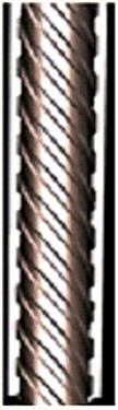
Spiral construction of tubes provides the following benefits:
1. For the same cross-sectional heat receiving area the number of inclined tubes is less than the number of vertical tubes to envelope the furnace without increasing the spacing between the tubes.
2. Uniform heat absorption in each tube renders the spiral wall system less sensitive to changes in the heat absorption profile in the furnace.
3. Increased mass flow rate of water in the tubes to a value that will prevent the DNB at partial loads, so there is no risk of tube starvation, and overheating is limited due to the critical heat flux/dry-out. It also equalizes the heat absorbed by water-wall tubes and thus limits the tube-to-tube temperature unbalance at the outlet of the furnace water-wall circuit (Figure 2.30).

However, spiral-tube construction involves a complex support structure, which raises fabrication costs, and it is also relatively difficult to erect and repair spiral tubes.
The vertical water-wall design uses rifled tubing for improved mass flow without DNB or dry-out at part loads. Its advantages lie in ease of maintenance, along with the potential to lower costs, and it is much easier to erect, support, and repair. The main disadvantage of the rifled tube water-wall design is the overall height of the boiler is excessive.
2.10.3 Steam-water cycle
A typical steam-water cycle of a supercritical plant is shown in Figure 2.31, which shows that the expansion of steam from state 1 to the condenser pressure would cause the exhaust vapor to become very wet and may cause severe damage to the low-pressure turbine stages. Hence, this cycle has to essentially use single reheat, and if the high-pressure turbine inlet temperature is low (813 K or less) and pressure is high (above 26 MPa) double reheat may also be required.

2.10.4 Special features
1. Supercritical boilers are essentially once-through boilers because of a gradual change in density from the liquid phase to the vapor phase. Hence, storage vessel of subcritical boiler, i.e., boiler drum, is no longer valid for the supercritical one.
2. The volume of the evaporator system of a once-through boiler is much smaller compared with a natural circulation boiler. Due to smaller inventory of stored water and steam, the theoretical rate of response on the load changes of a supercritical unit is much faster than for the drum unit.
3. These boilers are better suited for frequent load variations than drum-type boilers, since the drum is a component with a high wall thickness, requiring controlled heating. Therefore, pressure changes in a supercritical boiler can be achieved more easily, and these boilers require 15–20% less cold start-up time compared with that needed for subcritical boilers of the same size.
4. A once-through boiler does not have any boiler blow-down, therefore, less waste water is disposed of and eventually condensate make-up is usually significantly less.
5. In a supercritical unit the main steam temperature is controlled by the water-fuel ratio control with back-up spray attemperation. As a result, the rated steam outlet temperature can be achieved at all loads with all types of fuel.
6. The wall-thickness of HP turbine section of a supercritical plant should be high enough to withstand elevated pressure and temperature, yet in order to increase the thermal flexibility and fast load changes the thickness has to be as low as possible to avoid large amount of material that would require controlled heating.
2.10.5 Advantages
1. Reduced fuel costs due to higher plant efficiency
2. Significant reduction in CO2 emissions
3. Reduced NOx, SOx, and particulate emissions
4. Excellent availability, equal to or higher than that of a subcritical plant
5. Plant costs comparable with subcritical technology and less than other clean coal technologies
6. Maintenance costs of supercritical units are comparable to subcritical plants, if not better
7. Compatible with biomass co-firing
8. Can be fully integrated with appropriate CO2 capture technology
2.10.6 Disadvantages
1. Boiler pressure drop is higher than that with a subcritical unit. As a result, boiler feed pump power consumption is higher than that of equivalent size drum type boiler.
2. Cost of high-temperature and high-pressure superheater and reheater alloy steel is exorbitant.
3. Superior water quality essentially requires a 100% condensate polishing unit, increasing overall costs.
4. Proven performance with high-ash Indian coal has yet to be established.
5. Not suitable for sustained constant pressure operation at part load.
6. Design of furnace sizing is critical. Improper sizing may cause slagging problems.
7. Inappropriate flow through evaporator tubes results in reduced mass flux that may lead to tube failure.
Nonetheless, power plants operating with supercritical steam conditions show lower emissions of CO2, SOX and NOX, higher efficiency, flexibility and operating reliability, reduced fuel costs, and investment costs compared to subcritical plants.
2.10.7 History
The first application of supercritical technology in a power plant took place in 1957 in the United States. It was the Philo Unit 6 of the American Electric Power with a capacity of 125 MW designed with the superheater outlet steam conditions of 31 MPa and 883 K along with a double-reheat steam temperature of 839/811 K. Within two years, the 325 MW Eddystone Unit 1 of the Philadelphia Electric Company started operating with superheater outlet steam conditions of 34 MPa and 922 K along with a double-reheat steam temperature of 839/839 K.
The performance of these plants, however, was unreliable, expensive, and they had poor operational flexibility, mostly related to thermal effects. As a result, most countries stayed with subcritical technology. However, development continued in the 1970s and 1980s in inland Europe and Japan to explore the benefits of supercritical technology.
It should also be noted that the former USSR was not far behind the United States in the use of supercritical technology. The first supercritical power plant with a capacity of 300 MW was commissioned in the USSR in 1963, and the first 800 MW unit was put into operation in 1968. Unlike the United States, the USSR approach toward adopting supercritical steam conditions was quite modest, while steam pressure was raised to 25.5 MPa, superheat steam temperature was kept the same as that of the subcritical plants, i.e., 818 K, and the reheat steam temperature was either the same as the superheat temperature or slightly higher, at 818–838 K. The world’s largest supercritical unit with a capacity of 1200 MW has been operating in the USSR since 1980 [16].
From the 1980s on, the technology got so matured that currently there are more than 600 supercritical power plants operating in the United States, Russia, Denmark, Germany, Poland, Japan, China, Korea, South Africa, India, Australia, and Taiwan. Power producers in other countries are also embarking on supercritical technology.
When considering supercritical steam conditions research shows that the industry is predominantly adopting a superheat steam pressure in the range of 24–31 MPa, with superheat/reheat steam temperatures in the range of 838–883 K [17]. In the near future the focus will likely be on adopting steam conditions of 31–32 MPa and 893 K/893 K with the ultimate goal of reaching ultra-supercritical steam conditions of 34–36 MPa pressure and 973/993 K temperature [17].
2.11 Problems
2.1 Steam is generated at a pressure of 10 MPa with 150 K superheat. If the rate of steam generation is 100 kg/s and the feedwater temperature at the economizer inlet is 463 K, determine the rate at which the heat must be supplied. (Assume enthalpy of compressed liquid is the same as the enthalpy of saturated liquid.)
(Ans.: 246595 kJ/s)
2.2 In a pressurized vessel water at 8 MPa pressure is heated by an immersion-heating coil. Find the maximum heat flux at the limit of nucleate boiling. Also determine the difference in temperature between the heating surface and the temperature of the fluid, if the heat transfer coefficient of the fluid is 160 W/m2 K.
(Ans.: qmax=1088 W/m2; ΔT=6.8 K)
2.3 A 15-m long carbon-steel tube of 25 mm diameter is heated externally to 423 K. Water enters this tube at 2 MPa pressure with an average velocity of 3.06 m/s. While passing through the tube water is heated from 313 K to 393 K.
Find the “mean film temperature, Tm.” Calculate the convective heat transfer coefficient and the heat transfer to the water by forced convection. (Neglect the thickness of the tube and friction drop inside the tube.)
(Ans.: Tm=388 K; h=17.73 kW/m2 K; Q=1285.95 kW)
2.4 A furnace wall is comprised of a 200-mm thick fire clay wall with an average thermal conductivity of 0.26 W/m.K. Determine the heat loss through the wall when the inside temperature of the furnace is 1253 K and temperature outside the wall is 328 K. If the ambient air temperature is 300 K, what is the surface coefficient of the wall material?
(Ans.: Q=1202.5 W/m2; f=42.95 W/m2.K)
2.5 An 80 mm outer diameter pipe carrying steam at 508 K is lagged with glass fiber of 25-mm thickness. Find the heat loss to ambient air if its average temperature is 395 K. The thermal conductivity of glass fiber may be taken as 0.045 W/m.K and the average surface coefficient as 40 W/m2.K.
(Ans.: Q=252.77 W/m2)
2.6 A carbon-steel pipe has an internal diameter of 250 mm and an outside diameter of 275 mm. The outside of the pipe is covered with a layer of mineral wool that is 25 mm thick and has a thermal conductivity of 0.037 W/m.K. The inside temperature of the pipe is 623 K and the ambient air temperature is 298 K. Calculate the heat loss through the pipe and the surface coefficient of the insulating surface if the cold surface temperature is maintained at 333 K. Given: the thermal conductivity of carbon steel is 48 W/m.K.
(Ans.: Q=466.98 W/m2; f=10.2633 W/m2.K)