
Fluidized-Bed Combustion Boilers
Fluidized-bed combustion is a process in which solid particles are made to exhibit fluid-like properties by suspending these particles in an upwardly flowing evenly distributed fluid stream. Fuel flexibility and reduced emissions are the benefits of fluidized bed combustion. There are two basic categories of fluidized-bed combustion, i.e., atmospheric fluidized bed combustion (AFBC) and pressurized fluidized bed combustion (PFBC). Each category is further comprised of bubbling fluidized bed combustion (BFBC) and circulating fluidized bed combustion (CFBC). Out of these four configurations atmospheric CFBC has the widest global application and pressurized BFBC has limited commercial application. Fluidized-bed technology is a viable option to stoker-fired and pulverized coal-fired units for the combustion of solid fuels for fuel flexibility and reduced generation of atmospheric pollutants.
Keywords
fixed-bed; fluidized-bed; minimum fluidization velocity; terminal velocity; bubbling-fluidized bed; circulating-fluidized bed
5.1 Brief History
Fluidized-bed technology was initiated in the 1920s as a process for refining petroleum and for the production of chemical feedstock from coal. This technology has been applied for the following since the 1940s:
However, fluidized-bed technology as an alternative method for combustion of coal gained popularity in the 1950s when researchers started looking for ways to reduce atmospheric pollutants such as SO2 and NOX [1]. During the second half of the 1980s, fluidized-bed combustion (FBC) rapidly emerged as a viable option for stoker-fired and pulverized coal-fired units for the combustion of solid fuels due to following:
i. Rise in cost of conventional fuel and demand for multi-fuel firing
iii. Stringent SO2 and NOX emission regulation
iv. Availability of only low-grade coal for firing in boilers in some countries
vi. Low combustion temperature
vii. High heat and mass transfer
ix. Less capital investment compared to that required to install pulverized coal-fired boiler
The use of bubbling fluidized-bed (BFB) technology in the electric utility industry in the United States began in 1976 [2]. The first application of circulating fluidized-bed (CFB) technology in the United States occurred in 1981 and became operational by 1988. In Germany, although development of CFB combustors began in 1955, the CFB technology was first applied to the combustion of coal in 1982 when a co-generation unit set up [2]. By that time FBC technology had reached commercial status and was well-established for generation of heat, power, as well as combined heat and power.
With the constant development and refinement of the technology the use of CFB technology has expanded from small industrial boilers of capacity equal to or less than 30 kg/s to large utility boilers. By the early 1990s, several electrical utility steam generators had been in operation globally in the range of 100–165 MW [2]. The world’s largest sub-critical circulating fluidized bed combustion (CFBC) with a capacity of 250 MW was synchronized on October 29, 1995, and is in operation at Provence Power Station, France [3]. The largest supercritical CFBC plant is the 460 MW Lagisza plant in Poland. It started at the site in February 2006 and the project was commissioned in June 2009 [4,5]. Supercritical CFB boiler for which a detailed boiler design for up to 600 MWe CFB is now ready for first implementation with steam conditions 27 MPa/853 K/873 K and economizer inlet feedwater temperature 563 K [6]. Some of the world’s large CFBC boilers successfully operating in various countries are listed in Table 5.1.
Table 5.1
List of some of the world’s large CFBC boilers
| Sl. No. | Unit size MW | Fuel | Location | Year of commissioning |
| 1 | 4×125 | Waste coal, Slurry | Emile Huchet, France | 1990 |
| 2 | 2×125 | Lignite | Akrimota, India | 2003 |
| 3 | 2×220 | Anthracite | Tonghae, Korea | 1999 |
| 4 | 250 | Sub-bituminous | Provence, France | 1998 |
| 5 | 2×250 | Brown coal | Red-Hill, USA | 2001 |
| 6 | 2×250 | Bituminous | Guyama, Puerto Rico | 2003 |
| 7 | 300 | Anthracite | Biama, China | 2004 |
| 8 | 2×150 | Coal and Bio | Tha Toom, Thailand | 1999 |
| 9 | 202 (BFB) | Bio fuel | Power River, Canada | 1999 |
| 10 | 220 | Lignite | Chorzow, Poland | 2003 |
| 11 | 6×235 | Brown coal | Elektronia Turow, Poland | 1998–2005 |
| 12 | 2×300 | Bituminous | JEA Florida, USA | 2002 |
| 13 | 2×330 | Petcoke | Cleco, USA | 2009 |

5.2 The Technology
Fluidized-bed combustion is a process in which solid particles are made to exhibit fluid-like properties by suspending these particles in an upwardly flowing evenly distributed fluid (air or gas) stream [7]. Combustion takes place in the bed with high heat transfer to the furnace and low combustion temperatures.
The fluidized-bed process is shown schematically in Figures 5.1 through 5.10. When at rest the fluidized bed resembles a uniformly distributed bed of solid particles, e.g., sand stacked on a perforated plate of fine mesh at an intermediate position of an enclosed vessel (Figure 5.1). The perforated plate facilitates uniform distribution of fluid (air or gas) flow through the bed. At the bottom of the plate pressurized fluid is supplied.

When this pressurized fluid is allowed to pass upward through the bed of solid particles the bed tends to offer resistance to low fluid velocities such that the particles remain in contact and stay stagnant. This bed is called a fixed bed (Figure 5.2 and Figure 5.3).


With an increase in fluid velocity the particles offer less resistance and tend to expand. With further increase in fluid velocity a situation occurs in which particles are unable to remain in contact and start separating, resulting in bubble formation, vigorous turbulence, and rapid mixing. The motion of bubbles in this bed resembles the motion of bubbles in a liquid, and the bed of solid particles looks similar in appearance to a boiling liquid. At this point the drag force exerted on particles counterbalances the gravity force of the particles, thereby causing the fluid-solid mixture to behave like a fluid [7]. This is called the minimum fluidization condition of the bed (Figure 5.4) and the bed is called a fluidizing bed. The increase in the fluidizing-bed volume is insignificant when compared with the fixed bed. The transition from fixed bed to fluidized bed caused by the changes in air/gas pressure with an increase in fluid velocity through the solid bed is shown in Figure 5.5.


The velocity of the fluid at which the fixed bed transforms into the fluidizing bed is called the minimum fluidization velocity, denoted by vm, and it depends on the following factors:
The minimum fluidization velocity for spherical particles is given by [8]
(5.1)
vm: Minimum fluidization velocity, m/s
µ: Viscosity of the fluid, kg/m.s
dm: Mean diameter of particles, m
(5.2)
If the viscosity term of the fluid is neglected, then equating the drag force with the gravity force the minimum fluidization velocity for spherical particles can be calculated from Eq. 5.3:
(5.3)
where CD is drag coefficient, a function of the particulate shape and the Reynolds number, which is dimensionless [1]. (Typical value=0.6.)
Solving Eq. 5.3,
(5.4)
 (5.4)
(5.4)
As fluid flow increases further, particles accelerate. A physical condition is reached when the buoyant force and drag force of the particles balance the gravity force and relative velocity between the fluid and the particles reached a limiting value. This limiting relative velocity is called the terminal velocity (vt), which is expressed mathematically for the range of Reynolds number 0.4–500 as [8]
(5.5)
A further increase in the fluid flow causes the bed to become less uniform, bubbles of fluid to form, and the bed to become violent. This is called a bubbling fluidized bed (BFB), which is shown in Figures 5.6 and 5.7. The volume occupied by the fluid-solid mixture increases substantially. For this case, there is an easily seen bed level and a distinct transition between the bed and space above.


By increasing the fluid flow further, the bubbles become larger and begin to coalesce, forming large voids in the bed. The solids are present as interconnected groups of high solids concentration. This condition is called a turbulent fluidized bed (Figure 5.8).

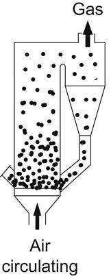
If the solids are caught, separated from the fluid, and returned to the bed they will circulate around a loop [7]. This type of system is called a circulating fluidized bed (CFB) and is shown in Figures 5.9 and 5.10. Unlike the bubbling bed, there is no distinct transition between the dense bed in the bottom of the container and the dilute zone above. The solids concentration gradually decreases between these two zones.

A commercial fluidized bed is comprised of sand, limestone, or sorbent, refractory, or ash along with only 3–5% coal. Above the fluidized bed there is provision for sufficient free-board height to prevent excessive elutriation of bed material or unburned carbon at the operating fluidizing velocity. The main feature of a fluidized bed is that throughout the combustor a homogeneous temperature is maintained at around 1073–1223 K. Thus, sintering of the bed is avoided, which takes place once the temperature exceeds 1223 K while burning coal. The above temperature range also suggests that combustion should take place at a minimum temperature of 1073 K below which combustion efficiency declines.
In most fluidized-bed boilers a low excess air level is achieved by providing an in-bed tube bundle designed to extract the heat released in excess of the heat removed by the gas. The majority of the heat in the gas is recovered in convective heat transfer surfaces. A fluidized bed of particles is capable of exchanging heat very effectively with fluidizing gas because of the very large surface area exposed by the particles. With its relatively low heat capacity the gas will rapidly approach the temperature of the solids it is fluidizing. It is the temperature of the solids that dominates the bed thermal behavior because of its high heat capacity, and it is the gas temperature that follows temperature of the particles.
Fuel flexibility and reduced emissions are the benefits utilities can gain by adopting FBC. FBC is appropriate for firing a variety of solid fuels, e.g., coal, petro-coke, biomass, wood, coal washery rejects, etc., with varying heating value, ash content, and moisture content in the same unit. The calorific value can be as low as 7.5 MJ/kg.
In FBC, pollutants in products of combustion are reduced concurrently with combustion – much of the ash and hence the particulate matter is removed during the combustion process, including sulfur. In addition, FBC occurs at much lower temperatures than the combustion temperatures of 1573–1773 K required in pulverized coal-fired boilers, thus resulting in lower production of NOX. This reduced combustion temperature also helps avoid slagging problems with inferior grades of coal. The resulting ash of this boiler is less erosive in nature. Oil support requires a much lower load, about 25%, than that required in pulverized coal-fired boiler, which is about 40%.
The residues from FBC consist of mineral matter content of the as-fired fuel, as well as residual sorbent, i.e., CaO/MgO/CaSO4/CaCO3. High free lime may also be present in the residues. As a result strongly alkaline matter will leach from the bed.
5.3 Categories of FBC
There are two basic categories of FBC: atmospheric fluidized-bed combustion (AFBC) and pressurized fluidized-bed combustion (PFBC). NFPA 85 defines AFBC as “a fuel-firing technique using fluidizing-bed operating at near-atmospheric pressure on the fire side” [9]. The AFBC option is further comprised of two types: bubbling fluidized-bed combustion (BFBC) and CFBC. In AFBC, steam is generated for power production using the conventional Rankine cycle.
A fluidizing bed in which the fluidizing velocity exceeds the terminal velocity of individual bed particles and in which part of the fluidizing gas passes through the bed as bubbles is called a bubbling fluidized bed. In a circulating fluidized bed the fluidizing velocities substantially exceed the terminal velocity of the individual bed particles where the bed and the free board above the bed cannot be distinguished and become a uniform fluidized bed.
PFBC units operate at 1.0–1.5 MPa pressure and offer the potential of smaller boilers in comparison with AFBC [10]. In a PFBC boiler, the combustion gas temperature at the exit of the boiler is in the range of 1088–1143 K, which is further used to drive a gas turbine. PFBC boilers are normally used in combined cycle units [11]. Combustion efficiency of PFBC is better than that of AFBC. As with AFBC, two configurations, i.e., bubbling bed and circulating bed, are also possible in PFBC.
Out of above four configurations of FBCs, atmospheric CFBC finds the widest application globally.
5.3.1 Advantages
The advantages of FBC boilers over conventional boilers are:
i. Combustion efficiency of FBC is comparable to that of conventional boilers because of effective contact among heated bed material, gas, and solid fuel even though the bed temperature is low.
ii. An environmentally attractive feature of FBC is that sulfur dioxide (SO2) can be removed in the combustion process by adding sorbent (e.g., slaked lime (CaO) or limestone (CaCO3) or dolomite (CaCO3·MgCO3)) to the fluidized bed, eliminating the need for an external scrubber or flue gas desulfurization (FGD) plant. The sorbent, in combination with oxygen from the supplied air, absorbs sulfur dioxide according to the following reactions:
(5.6)
(5.7)
(5.8)
The maximum rate of this reaction is achieved at bed temperatures between 1088 and 1143 K, even though a practical range of fluidized-bed operation of 1023–1223 K is common [1]. All lime and limestone units are designed for 90–95% SO2 removal. Magnesium-enhanced lime systems are designed for 95–98% removal [12]. The compound CaSO4·2H2O, produced in this process is gypsum, which is either regenerated or used in cement plants.
iii. Compared to the combustion temperature of conventional boilers, approximately 1573–1773 K, the combustion temperature of a FBC is quite low. Combustion at lower temperatures has several benefits:
1. Lower temperature minimizes sorbent requirements because the required Ca/S molar ratio for a given SO2 removal efficiency is minimized in this temperature range (Figure 5.11) [13].
2. Bed temperature of 1023–1223 K is well below the ash-fusion temperature of most fuels so the fuel ash never reaches its melting point. The slagging and fouling characteristic of pulverized-coal units are significantly reduced, if not eliminated.
3. Lower temperature reduces NOX emissions.
iv. FBC can be designed to incorporate the boiler within the bed, resulting in volumetric heat-transfer rates that are 10–15 times higher and surface heat-transfer rates that are 2–3 times higher than a conventional boiler. A fluidized-bed steam generator is therefore much more compact than a conventional one of the same capacity [1].
v. In addition, reduction in SO2 (and SO3) in the flue gas means that lower stack gas temperatures can be tolerated because less acid is formed as a result of the condensation of water vapor. Lower stack-gas temperatures result in an increase in overall plant efficiency.
vi. With a suitable ash cooler, bottom ash is available at a comparatively lower temperature (below 573 K), enhancing boiler efficiency.
vii. Variation in moisture content in fuel does not cause problems as in the case of conventional boilers. When introduced into the bed fuel gets immediately mixed with the bed material and the water of fuel gets vaporized and superheated on admission. As a result, the dried fuel particles reach the ignition temperature and burn in fluidizing air.
viii. Flexibility to use a wide range of fuels in the same boiler. Some of the fuels that can be successfully fired in FBC boilers are coal, peat, washery rejects, lignite, sludge, wood waste, bagasse, straw, husk, bark, paper waste, petroleum cake, biomass, etc.
ix. Even with low-grade fuel FBC boilers will generate rated output.
x. Fine coal of size below 6 mm [14], which are difficult to burn in conventional boilers, can be efficiently burnt in FBC boilers.
xi. Lower combustion temperature, softness of ash, and low particle velocity result in less corrosion and erosion effects.
xii. Due to high turbulence in the bed quick start-up and shut down are feasible.
xiii. Load following is more appropriate for automation because of inherent high thermal storage.
xiv. The boiler is more compact and thus less expensive.
xv. Maintenance cost is low since routine overhauls are infrequent.

5.3.2 Disadvantages
Some of the typical problems experienced during operation of FBC boilers include:
i. Size and shape of the particle plays a vital role. Over-size particles result in improper fluidization and impair the combustion process. Thus efficiency of boiler gets reduced. Too large a particle may lead to smoldering.
ii. In the event coal particles become under-sized, some of them may escape the free-board (firing) zone, resulting in burning of fine carbon particles around the cyclone, consequently there will be excursion of flue gas temperature beyond the furnace zone.
iii. Fluidizing nozzles sometimes get plugged, inhibiting proper fluidization of the fuel bed.
iv. It is very important to maintain optimum fluidizing velocity. In the event that velocity is inadequate incomplete combustion will result.
When the fluidizing velocity exceeds the limit, the heat transfer coefficient drops, causing the bed-wall heat transfer to fall. Erosion may occur in radiant superheater and convective heat-exchanging surfaces.
v. Gradual and undetected wear of boiler parts.
vi. At times, bed ash gets accumulated when removed manually, and bed height exceeds the permissible limit. A higher bed height may increase bed resistance, resulting in improper fluidization of the bed. As a result, the bed temperature may exceed the recommended upper limit, causing sintering of bed ash and associated problems. A higher bed height also enhances bed pressure.
vii. Bed temperature may exceed the recommended upper limit if the loop-seal air supply is inadequate and/or primary airflow is low. Low primary airflow may also cause the wind-box pressure to rise.
5.4 Design Variables
For the design of a fluidized-bed boiler the first step is to calculate the fuel-feed rate according to the required thermal output of the boiler with a targeted efficiency. Then the stoichiometric air supply requirement is calculated, which is further enhanced by the design excess air quantity. It is also essential to estimate the net heat release rate and its utilization to arrive at the temperature of the flue gas. The heat transfer from this hot gas to various heat-absorbing surfaces is then calculated. The next step is to find out the amount of sorbent requirement to ensure sulfur capture as per environment-protection standards.
The bed temperature is greatly influenced by fuel composition. For high-sulfur fuel, e.g., pet-coke, the bed temperature has to be maintained at around 1123 K for optimum sulfur capture. While low-sulfur low reactivity fuel, like anthracite culms, can be safely operated at a higher temperature to ensure high combustion efficiency. In the case of low-grade fuel less heat is absorbed in the fuel bed and bulk of the heat is absorbed in the convective surface.
Bed pressure drop resulting from static weight of solids in the bed is calculated as [1]
(5.9)
α: Fraction not occupied by solids (voids) in fixed bed, dimensionless (the typical value is 0.40, for particles of equal diameter)
The air-distributor grate of CFBC is less critical than that of BFBC, since erosion of bed internals and heat exchanger tubes is a major concern for BFBC. In CFBC, air-distributor grates are narrow, deep, and operate at much higher velocity to distribute the fluidizing air uniformly over the cross-section of the bed.
Solid wastes produced from fluidized-bed boilers require special design attention, since the total quantity of solid waste is much higher than that produced from an equivalent-size pulverized coal-fired boiler.
The amount of sorbent, e.g., limestone, dolomite, etc., required depends on the sulfur content of the fuel, bed temperature, properties of ash content of fuel, emission restrictions, particle size distribution, reactivity of sorbent, etc. Figure 5.12 shows how the amount of sorbent is affected by the bed temperature and sulfur capture rate [15].

Considering all of the above aspects as well as ensuring optimum performance of the FBC boiler, the design variables, which primarily affect efficiency, sulfur capture, and operational flexibility, are as given in Table 5.2.
Table 5.2
| Sl. No. | Parameters | Principal effect |
| 1. | Fluidizing Air Velocity (Superficial Velocity) | Mixing of Bed Material, Elutriation of Fines, Erosion of Bed Tubes |
| 2. | Bed Depth (BFBC) | Residence Time, Fan Power Consumption |
| 3. | Free Board Height | Elutriated Fines, Staged Combustion |
| 4. | Coal-feed Size | Combustor Design |
| 5. | Excess Air | Combustion Efficiency, Heat Loss |
| 6. | Calcium/Sulfur (Ca/S) Ratio | Desulfurization Efficiency, Combustion Efficiency |
| 7. | Gas Recirculation | Turn–Down, Part Load Efficiency |
| 8. | Grit/Ash Recirculation | Desulfurization Efficiency, Combustion Efficiency |
| 9. | Bed Temperature | SO2 and NOX emission |
5.4.1 Basic parameters
In addition to the design variables discussed in the previous section the basic parameters that need to be considered during the design stage of BFBC and CFBC boilers are given in Table 5.3.
Table 5.3
| Sl. No. | Description | BFBC boiler | CFBC boiler |
| 1. | Fluidizing Velocity, m/s | 1.2–3.7 | 3.7–9.0 |
| 2. | Coal-feed Particle Size (max), mm | Under Bed Feed: 6–10 | 6–10 |
| Over Bed Feed: 20–32 | |||
| 3. | Mean Bed Particle Size, μ | 500–1500 | 150–500 |
| 4. | Depth of Bed, m | 0.9–1.5 | No Distinguished Bed Level. |
| Suspension Density Close to BFBC at Bottom and Gradually Thinning Toward Top | |||
| 5. | Bed Pressure Drop, kPa | 20–25 | 10–18 |
| 6. | Bed-Surface Heat Transfer Coefficient, W/m2K | 200–550 | 100–250 |
| 7. | Grate Heat Release Rate, MWth/m2 | 0.5–1.5 | 3–5 |
| 8. | Entrainment Rate, kg/m2s | 0.1–1.0 | 10–40 |
| 9. | Combustion Efficiency, % | 90–96% | More than 98% |
| 10. | Boiler Efficiency (based on HHV), % | 82–85% | 86–87% |
| 11. | NOx Emission, ppm | 300–400 | 100–200 |
| 12. | Calcium/Sulfur Ratio | 3.0–4.5 | 1.5–2.0 |
| 13. | Excess Air, % | 20–25 | 10–20 |
| 14. | Preferable Boiler Size, tph | Below 100 | Above 50 |
| 15. | Turn – Down Ratio | With Slumping – 5:1 | 3:1–4:1 |
| Without Slumping – 2:1 | |||
| 16. | Number of Coal-feed Points | Under Bed Feed – 1 Per m2 of Bed Area | 1 Per 10–30 m2 of Bed Area |
| Over Bed Feed – 1 Per Bed Compartment | |||
| 17. | Moisture in Coal | Under Bed Feed – Coal Pipe Choking | No Problem |
| Over Bed Feed – No Problem | |||
| 18. | Excess Fines in Coal | Under Bed Feed – No Problem | No Problem |
| Over Bed Feed – Affects Efficiency | |||
| 19. | Agglomeration | Some | No problem |
| 20. | Start-Up Time | High | Low |
| 21. | Oil Support | Not Required | Required Below 25% Load |

5.5 Bubbling Fluidized-bed Combustion (BFBC) Boilers
In a bubbling fluidized-bed unit the fluidizing velocity is low (1.2–3.7 m/s). As a result, the particles are held mainly in a bed that has a depth of 1 m or so and has a definable surface, as already discussed in section 5.2. The combustion of heat is absorbed from the gas by the heat transfer tubes immersed in the bed and by a conventional water-wall surface. The in-bed tubes can serve as either a steam-generation surface or a superheat surface and are used to control the bed temperature. Although an in-bed heat exchanger is a possible source of erosion problems, the close contact with the bed materials and excellent mixing provide high heat transfer. Heat transfer in the convection pass is similar to that for a conventional stoker-fired or pulverized coal-fired steam generator.
Figure 5.13 shows a bubbling-bed combustor, where the hot-bed material is in a state of suspension and behaves like a bubbling liquid by fluidized air. The bed temperature (1073–1173 K) is controlled by varying the amount of fuel and air within the bed.

As coal particle size decreases to about 250 micron, either as a result of combustion or attrition, the particle is elutriated from the bed and carried out of the combustor. These elutriated particles are then removed as fly ash. This loss of unburned carbon results in a combustion efficiency of 85–90%. By recycling grit and ash from the cyclone separator back into the bed, the combustion efficiency can be increased to 96%.
Sand is often used for bed stability, together with limestone or dolomite for SO2 absorption. Since combustion takes place at 1073–1173 K, generation of NOX is also low as compared to that of a pulverized coal-fired boiler. Flue gases are normally cleaned using cyclone, then gases pass through further heat exchangers. The fuel-feed size in this bed is restricted to 30 mm in top size, with 20% about 6 mm. The BFBC unit size is generally of the order of 25 MWe, although larger sizes are also of use for retrofitting existing units.
The unburned carbon level is higher than that of a pulverized coal-fired boiler. Another disadvantage of BFBC is that to remove SO2, a much higher Ca/S ratio (resulting in higher limestone or dolomite consumption) is needed than for CFBC. This increases costs, in particular the cost of residue disposal. Other disadvantages are higher carbon loss, higher fan power consumption, erosion of bed tubes, etc. Chloride content in fuel accelerates erosion.
The bottom ash of this boiler comprises about 30–40% of the total ash, with the remaining being fly ash.
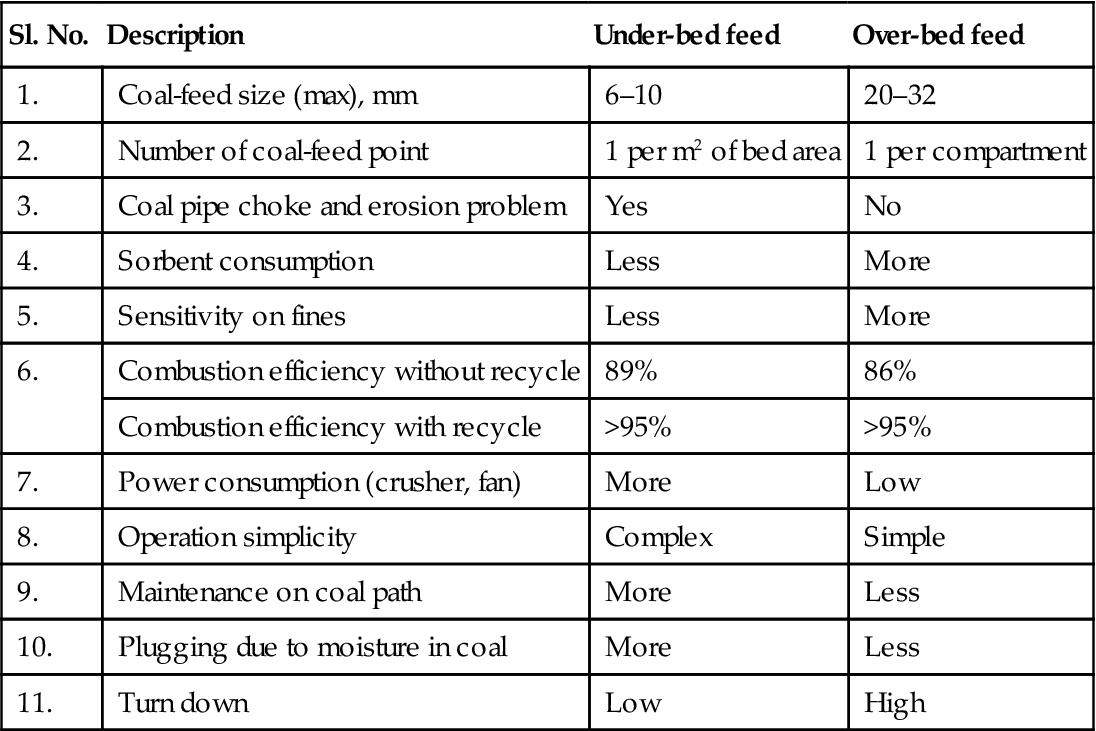
There are two types of fuel-feeding systems in a BFBC boiler, e.g., under-bed feed and over-bed feed (Figure 5.14) [12]. A comparison of these two types is given in Table 5.4.

Table 5.4
Comparison of coal-feeding systems in BFBC boilers
| Sl. No. | Description | Under-bed feed | Over-bed feed |
| 1. | Coal-feed size (max), mm | 6–10 | 20–32 |
| 2. | Number of coal-feed point | 1 per m2 of bed area | 1 per compartment |
| 3. | Coal pipe choke and erosion problem | Yes | No |
| 4. | Sorbent consumption | Less | More |
| 5. | Sensitivity on fines | Less | More |
| 6. | Combustion efficiency without recycle | 89% | 86% |
| Combustion efficiency with recycle | >95% | >95% | |
| 7. | Power consumption (crusher, fan) | More | Low |
| 8. | Operation simplicity | Complex | Simple |
| 9. | Maintenance on coal path | More | Less |
| 10. | Plugging due to moisture in coal | More | Less |
| 11. | Turn down | Low | High |
BFBC boilers are mainly used in township heating systems or in industrial applications. Gas flow path of a typical BFBC boiler is given in Figure 5.15 [7].

Compared to a stoker-fired boiler a BFBC boiler has the following advantages:
5.6 Circulating Fluidized-bed Combustion (CFBC) Boilers
In a circulating fluidized-bed unit, the bed material is comprised of fuel, fuel ash, sorbent, and other inert bed materials. The bed is supported within the furnace by air flowing into the bed from the bottom of the furnace. The air flow supports the bed and ensures complete combustion by providing close mixing of fuel and air.
This type of boiler is capable of burning low volatile content, typically 8–9%, fuel, e.g., pet-coke, and fuels with low ash-melting temperature, e.g., wood, biomass. It can also burn fuels with ash content as high as 70%, e.g., coal washery rejects. Fuels with high moisture content, such as lignite, can also be burnt in this boiler.
In a circulating fluidized-bed unit, combustion of heat is absorbed from the gas by a conventional water-wall surface, by platens located in the upper region of the combustor, or by a heat transfer surface located in external heat exchangers.
The velocity of the gas in a CFBC boiler is relatively higher than that of the solids. The high slip velocity (the difference between the mean gas velocity and the mean solid velocity; see Figure 5.16) [2], in combination with long residence and contact times and intense mixing, results in higher heat and mass transfer rates and higher combustion efficiency in CFBC than are available with BFBC.

The circulating fluidized bed, as shown in Figure 5.17 [16], has been developed to improve combustion efficiency and reduce sorbent consumption for required level of desulfurization. In this boiler, higher fluidizing air velocity (3.7–9.0 m/s) results in the coal and inert bed material being entrained and carried through the combustor and overboard region into the hot cyclone. Thus, a distinct dense fluidized bed does not exist at higher load in this case. The coarse particles of sorbent and unburned coal are recovered in the cyclone and are recycled to the combustor. Individual particles may recycle anything from 10–50 times, depending on their size, and how quickly the char burns away.

The primary air is injected below the air-distributor plate located at the furnace floor and the secondary air is injected at a certain height above the furnace grate to ensure complete combustion. Fuel particles are burnt in the furnace to release heat. Part of the heat released is absorbed in the in-bed water-steam surface and the bulk of the remaining heat is absorbed in the convective heat transfer area.
The combustion zone extends beyond the furnace into the hot cyclone. The furnace heat release rate in a CFBC boiler is of the order of 3.5–4.5 MW/m2, which is compatible with that of a pulverized coal-fired boiler. For a bed burning bituminous coal, the carbon content of the bed is only 1%, while the rest of the bed is made up of ash, together with sand and/or lime and calcium sulphate. Because of the small particle size and recycling of solids back to the combustor, the CFBC boiler is able to achieve a combustion efficiency over 98% and a Ca/S ratio of 2.5 for 90% sulfur capture (Figure 5.11). The fuel-feed size in this boiler can be as low as 1.5 mm to 10 mm top size.
Contrary to a BFBC bed, a CFBC bed is not provided with steam-generating tubes. To capture and recycle large bed materials CFBC boilers are provided with big cyclone separators, requiring the boiler to be very tall (Figure 5.18.).

The CFBC boiler is used in number of units around 250–300 MW in size. In a CFBC unit, heat losses from the cyclone(s) are considerable. Thus, the thermal efficiency of a CFBC boiler is 3–4% lower than an equivalent-size pulverized coal-fired boiler. The operating performance of the CFBC boiler shows that whenever there is a need to increase load on the boiler it can be achieved by raising the bed temperature and keeping the bed material height unchanged (Figure 5.19) [15]. From the operating performance it is further noted that if the bed temperature is maintained the boiler load is linearly related with the bed material height (Figure 5.20) [15].


The advantages of a CFBC boiler compared to a BFBC boiler are:
a. Higher combustion efficiency
f. No limitation on boiler size
h. Reduced axial dispersion of gas
i. Reduced cross-sectional area due to higher fluidizing velocity
j. Potentially more control over suspension-to-wall heat transfer because of the ability to use the solids circulation flux as an additional variable
k. No region like the free-board region of BFBC, where there can be substantial temperature gradients
l. Less tendency to show particle segregation and agglomeration
m. Easier to have staged processes
n. Because of superior radial mixing, fewer solid feed-points are needed
Some of the disadvantages of a CFBC boiler over a BFBC boiler are:
5.7 Pressurized Fluidized-bed Combustion (PFBC) Boilers
As discussed earlier by burning coal in a fluidized bed at low temperature it is possible to avoid sintering of coal ash and to minimize volatilization of alkali metals in the fuel. Thus, hot gas can be safely used in a gas turbine since the above properties ensure reduction of corrosion and erosion of gas turbine blades. To harness these benefits the pressurized fluidized-bed combustion (PFBC) boiler was developed in the late 1980s and considerable effort was devoted to the development of PFBC during the 1990s. Today, a PFBC is capable of burning all types of coal, even low-grade coal, be it high moisture, high ash, high sulfur, low gross calorific value (GCV) etc. [11].
This type of boiler is used with a combined-cycle system, incorporating both steam and gas turbines [11]. A PFBC boiler generates steam to drive a steam turbine, while gas from the boiler drives a gas turbine. Such combination of Rankine cycle and Brayton cycle along with FBC provides higher cycle efficiency than the efficiency of conventional coal-firing systems, lower emissions, and harmless waste products. The steam turbine produces 80–90% of the generated power, and the gas turbine 10–20%. These boilers operate at pressures of 1.0–1.5 MPa with combustion temperatures of 1073–1173 K and can be used in compact units. Typical size of PFBC boilers is only 1/5 size of atmospheric boilers [11]. The combustion air is pressurized in the compressor section of the gas turbine.
Combustion at high pressure yields the following benefits:
The benefits of PFBC relative to AFBC are:
i. Specific power output of PFBC is higher, and hence the capital cost is less.
ii. Efficiency of the combined cycle is higher than that of the conventional cycle.
iii. Practically all the combustion takes place within the bed and free-board combustion is negligible, facilitating gas turbine operation with ease.
Along with these benefits PFBC also shares the inherent benefits of FBC, i.e., low SO2 emissions and less formation of NOX than in a pulverized coal-fired boiler. PFBC units are built to give an efficiency value of over 40% and low emissions. Systems using more advanced cycles should achieve efficiencies of over 45%. As with AFBC, two configurations, e.g., bubbling-bed and circulating-bed, are also possible in PFBC. Currently commercial-scale operating units all use bubbling beds.
The combustor and hot gas cyclones in a PFBC are enclosed in a pressure vessel. Both coal and sorbent, which reduce SO2 emissions, are fed across the pressure boundary. The bed material contains 90–95% of coal ash. The pressurized coal combustion system heats steam, in conventional heat transfer tubing, and produces a hot flue gas. Particulates are then removed from the hot flue gases prior to expanding the gases through a gas turbine. The exhaust gases are cooled, generating more steam for power production.
Figures 5.21 and 5.22 show a typical PFBC co-generation plant comprised of a steam generator with its steam turbine, gas turbine, fuel-handling, and ash-handling systems. The fuel is a mixture of crushed coal, sorbent, and water supplied as a paste with the help of piston pumps.


The world’s largest PFBC with a capacity of 360 MW in Karita, Japan was commissioned in 2000 and began commercial operations in July 2001 [17]. Global application of PFBC, however, is limited due to following requirement/restrictions:
i. Feeding coal has to be completely dried, virtually free from surface moisture, to maintain the coal-feed rate to the combustor.
ii. The need to pressurize the feed coal, limestone, and combustion air, and to depressurize the flue gases and the ash-removal system introduces significant operating complications.
iii. Heat release with each bed area is much greater in pressurized systems, and bed depths of 3–4 m are required to accommodate the heat-exchange area necessary for the control of bed temperature.
iv. At reduced load, bed material is extracted, so that part of the heat exchange surface is exposed.
v. PFBC has a large thermal capacity. Thus the heating rate of PFBC is much lower than that of the gas turbine, requiring some external arrangement for start-up of gas turbine.
vi. Hot gas from the combustor has to be sufficiently cleaned (from a dust concentration value of 10,000–40,000 ppm at the combustor outlet down to less than 300 ppm at the gas turbine inlet) to avoid erosion of gas turbine blades.
vii. The response of the gas turbine to load change is fast, while that of PFBC is sluggish, and as a result control becomes complicated.
viii. A PFBC power plant has huge auxiliary equipment that needs to be controlled along with many final control elements. Thus, the control system required for such a plant is essentially large in scale.
5.8 Start-Up and Loading of PFBC Boilers
Prior to starting (black start-up) a PFBC boiler the gas turbine generator is started as a synchronous motor taking its power supply from the grid. This facilitates starting of the gas turbine compressor, which supplies combustion air to the furnace. Then gas or oil-fired bed pre-heaters are lit. As the fuel is fed into the furnace both bed temperature and bed height start rising. When the bed temperature exceeds the ignition temperature of coal (the average temperature value is 923 K), continuous coal feeding to the bed takes place, and the coal will burn rapidly. When the bed temperature becomes uniform the supplementary firing system is gradually withdrawn. The boiler is now in a position to generate enough steam to run the steam turbine. The hot gas from the burning coal after proper treatment is passed through the gas turbine. As the load is increased the gas turbine generator switches from the synchronous motor to a synchronous generator. Both the bed temperature and main steam temperature are controlled by controlling the coal-feed rate and the bed height simultaneously. (Detailed treatment on ‘Start-up and Shut Down of Steam Generator’ is addressed in Chapter 12.)
5.9 Problems
5.1 Determine the minimum fluidization velocity of 300 μm sand, if the density of sand is 2500 kg/m3, density of gas is 0.316 kg/m3, and viscosity of gas is 4.49×10⁻⁵ N.s/m2.
(Ans.: vm=0.0368 m/s)
5.2 The mean bed particle size of a fluidized bed is 350 μm and the average density of solid particles is 1900 kg/m3. Find the terminal velocity of particles, if the gas density is 1.16 kg/m3 and the gas viscosity is 1.84×10⁻⁵ N.s/m2.
(Ans.: vt=2.305 m/s)
5.3 Find the Archimedes number, minimum fluidization velocity, and terminal velocity of particles in a fluidized-bed combustion chamber if the mean bed particle size is 400 μm and the average density of the solid particles is 2500 kg/m3. The maximum and minimum bed temperature is maintained at 1173 K and 298 K, respectively. Other given conditions are:
Gas density, kg/m3: 0.237 (at 1173 K) and 1.162 (at 298 K)
Gas viscosity, N.s/m2: 4.493×10⁻⁵ (at 1173 K) and 1.833×10⁻⁵ (at 298 K)
(Ans.: At 1173 K: Ar=184.26, vs=0.065 m/s, vt=4.000 m/s At 298 K: Ar=5425.84, vs=0.150 m/s, vt=3.164 m/s)
5.4 A fluidized bed combustion chamber is fed with crushed coal of size between 6 mm and 20 mm. Within the bed the mean bed particle size is 300 μm and the average density of solid particles is 1300 kg/m3. The bed temperature is maintained at 1123 K and the solid height of the bed is 1200 mm. Calculate the minimum gas velocity that fluidizes the coal bed and the pressure drop across the bed. (Assume the coefficient of drag is 0.6, average void fraction of collapsed bed is 0.25, and density of gas is 1.32 kg/Nm3.)
(Ans.: vs=5.15 m/s, ΔP=11.47 kPa)