
Gas Turbine and Heat Recovery Steam Generator
A gas turbine, also called a combustion turbine, is a rotary engine that extracts energy from a flow of combustion gas. The essential features of a gas turbine are the compressor, combustion chamber/s, and gas turbine. Compared with conventional steam power plants with large steam generators and bulky condenser, gas turbines, along with associated systems, are small in size and mass. Gas turbines offer flexibility in using a range of liquid and gaseous fuels. There are two basic types of gas turbines: aero derivative and industrial. The operation of a gas turbine follows the Brayton cycle. Performance of a gas turbine is improved by adopting regeneration, compressor intercooling, turbine reheat, water injection, cogeneration, combined cycle, and Cheng cycle. HRSG is used in a combined cycle power station, where hot exhaust from a gas turbine is fed to the HRSG to generate steam, which in turn drives a steam turbine.
Keywords
compressor; combustor; gas turbine; aero-derivative; industrial; simple cycle; combined cycle; improvement of performance; HRSG; pinch point; approach
7.1 Introduction
Back in 1500 Leonardo da Vinci (1452–1519) sketched a machine, called the “Chimney Jack,” that extracted mechanical energy from a gas stream. Hot air from a fire rose through a series of fans that connected and turned the roasting spit. Giovanni Branca developed a machine in 1629 in which jets of steam rotated a turbine that then rotated the driven machinery of a stamping mill. In 1678 Ferdinand Verbeist built a model carriage relying on a steam jet for power. In 1791 a basic turbine engine was patented with all the same elements as today’s modern gas turbines to power a horseless carriage. However, until the nineteenth century no practical implementation of such machines was considered. That is, until the American engineer George Brayton (1830–1892) proposed a cycle consisting of a gas compressor, mixing chamber, and expander that used a combustion chamber exhausting to the atmosphere.
In the original nineteenth-century Brayton engine, ambient air is drawn into a piston compressor, where it is compressed isentropically. The compressed air then runs through a mixing chamber where fuel is added at constant pressure (isobaric process). The heated (by compression) pressurized air and fuel mixture is then ignited in an expansion cylinder and energy is released, causing the heated air and combustion products to expand isentropically through a piston/cylinder. Some of the work extracted by the piston/cylinder is used to drive the compressor through a crankshaft arrangement. In 1872 German engineer F. Stolze patented a machine that predicted many of the features of a modern gas turbine engine, with a gas compressor, burner (or combustion chamber), and an expansion turbine, but the engine never ran under its own power.
The first gas turbine was built in 1903 by a Norwegian named Ægidius Elling that was able to produce more power than it needed to run its own components. At that time, knowledge of aerodynamics was limited, and Elling’s invention was considered a remarkable achievement. Using rotary compressors and turbines it produced an equivalent amount of about 8 kW power (substantially high at that time in respect of prevailing scenario). Elling’s work was later used by Sir Frank Whittle. The first application for a gas turbine engine was filed in 1914 by Charles Curtis. General Electric, one of the leading gas turbine manufacturers of today, started their gas turbine division in the year 1918. In 1920 Dr. A. A. Griffith applied the experience of gas flow past air foils into gas flow through passages of a turbine. Sir Frank Whittle patented the design for a gas turbine for jet propulsion in the year 1930. His work on gas propulsion relied on all works carried out earlier in the same field. Whittle once stated that his invention was greatly influenced by the work of Ægidius Elling in the absence of which it would have been difficult for Whittle to achieve his goal. The first successful use of his engine was in April 1937. In the year 1936, Hans von Ohain and Max Hahn of Germany developed their own patented engine design at the same time that Sir Frank Whittle was developing his design in England.
All of the aforementioned chronological development led to the first modern gas turbine plant being installed in 1950.
The modern-day gas turbine, also called a combustion turbine, is a rotary engine that extracts energy from a flow of combustion gas. The gas is normally air, or products of combustion of fuel and air. The essential features of a gas turbine are [1]:
i. Compressor that raises the air pressure
ii. Combustion chamber/s in which fuel is sprayed into the pressurized air from compressor for combustion
iii. Gas turbine through which high-temperature products of combustion from the combustor pass and are expanded
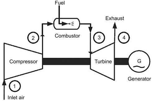
The upstream compressor is directly coupled to downstream turbine, and the combustor or combustion chambers are located in-between (Figure 7.1). The air is compressed in the compressor, after which it enters a combustion chamber where energy is released when air is mixed with fuel and ignited in the combustor. As a consequence of the combustion at constant pressure the temperature of air is increased. After leaving the combustion chamber the resulting high-temperature gases are directed over the blades of the gas turbine, spinning the turbine, which in turn powers the compressor. Finally, the gases are passed through additional turbine blades generating more thrust by accelerating the hot exhaust gases by expansion back to atmospheric pressure thereby performing useful work. Energy is extracted in the form of shaft power, compressed air, and thrust, in any combination of these, and used to power aircraft, trains, ships, electrical generators, and even tanks.
Gas turbines for industrial and utility applications have many advantages. Compared with conventional steam power plants with large steam generators and bulky condensers, gas turbines, along with associated systems, are small in size and mass. Thus, the transport of gas turbine units is simpler.
Gas turbines offer flexibility in using a range of liquid and gaseous fuels, such as crude oil, heavy fuel oil, natural gas, methane, and distillate “jet fuel,” gas produced by gasification processes using coal, municipal waste, and biomass, as well as gas produced as a by-product of oil refining.
Gas turbines are ideal for electricity generation in periods of peak electricity demand, since they can be started and stopped, quickly enabling them to be brought into service as required to meet energy demand peaks. They are smooth running, and their completion time to full operation is the fastest compared to other power generating plants. Gas turbines also have the lowest capital and maintenance costs. They are also subject to fewer environmental restrictions than other prime movers [2].
Their main disadvantage, however, is the high heat rate, which restricts its use for electricity generation. This restriction, nevertheless, could be overcome by adopting a higher turbine inlet temperature by using high-grade material capable of withstanding high metallurgical limit. For every 55 K increase in temperature, the work output of a gas turbine unit can be enhanced by about 10% and the heat rate reduced by approximately 1.5% [3]. Another disadvantage of the gas turbine is its incompatibility with solid fuels [2].
There are two basic types of gas turbines: aero derivative and industrial. Aero-derivative units were primarily designed as aircraft jet engines, modified subsequently to drive electrical generators. They are lightweight and thermally efficient, but usually more expensive than gas turbines built exclusively for stationary applications. Currently, the capacity of a single-unit stationary type of aero-derivative gas turbine is maximum 50 MW, with compression ratios in the range of 30:1, using a high-pressure external fuel gas compressor.
Industrial gas turbines are exclusively used for stationary power generation. The capacity of a single unit could be as high as 450 MW [4]. Industrial gas turbines have a lower capital cost per kilowatt installed than aero-derivative units. Other benefits of industrial gas turbines over aero-derivative gas turbines are they are more rugged, can operate longer between overhauls, and are more suitable for continuous base-load operation with longer inspection and maintenance intervals, and their compression ratio is low (up to 16:1), requiring no external fuel gas compressor. The disadvantages of industrial gas turbines are they are less efficient and much heavier.
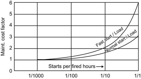
The fuel to be used in a gas turbine must be free of chemical impurities and solids as these either stick to the blades of the turbine or damage components in the turbine that operate at high temperature. When natural gas is used, the power output and thermal efficiency of gas turbines are higher than when using most liquid fuels. In contrast, about 6% of liquid fuel is wasted during combustion as compared to 11% for natural gas [5]. The relative maintenance cost is the lowest while firing natural gas in a gas turbine (Figure 7.2). The maintenance costs of a gas turbine are greatly influenced by i. the type of starting (normal/fast) (Figure 7.3), ii. the frequency of starting in a specified period (Figure 7.3), as well as iii. the loading pattern (Figure 7.4).


Gas turbines can be used in a variety of configurations as follows:
1. Simple cycle operation, i.e., a single gas turbine producing power only.
2. Combined heat and power (CHP) operation, which is a simple cycle gas turbine with a heat recovery heat exchanger that recovers the heat from gas turbine exhaust to generate low-pressure steam or hot water.
3. Combined cycle operation in which high-pressure steam generated from recovered exhaust heat is passed through a steam turbine to produce additional power.
When used in a simple cycle with no heat recovery, the heat left over in exhaust gases from the gas turbine set is substantial, to the extent of 60% or more of heat input to the set, and is lost to the atmosphere, resulting in poor thermal efficiency of a gas turbine. The gas exhausted from the turbine is not only plentiful and hot (673–823 K), but it also contains substantial amount of oxygen (normally a gas turbine operates with 300–400% excess air and its exhaust contains about 16–18% oxygen). A 50-MW gas turbine might discharge approximately 280 kg/s of exhaust gases at about 753 K, with an equivalent value of about 580*106 kJ/hr of energy or approximately 75% of initial fuel input. These factors point to using the hot, oxygen-rich gas in a steam-generating plant, whose steam output will drive a steam turbine. The use of such wasted heat in a heat-recovery steam generator (HRSG) is the basis of a “combined cycle gas turbine (CCGT)” plant (Figure 7.5).

A gas bypass stack and silencers are frequently installed downstream of the gas turbine (Figure 7.6) so that it can be operated independently of the steam cycle. Silencers are also installed at air inlet to compressor.

The approximate site performance of a gas turbine may be predicted by applying the following rule of thumb correction factors based on Original Equipment Manufacturer (OEM) recommended International Standards Organization (ISO) performance parameters [5]:
i. For each 0.56 K (1°F) rise in ambient air temperature above 288 K there would be about 0.3–0.5% drop in power output, with a proportionate increase in heat rate.
ii. For every 305 m (1000 ft) increase in site elevation above sea level, gas turbine power output would reduce by about 3.3%.
iii. For every 25-mmwc inlet pressure drop, power output is expected to be reduced by 0.5% with 0.1% increase in heat rate.
iv. For every 25-mmwc outlet pressure drop, the power output is expected to be reduced by 0.15% with 0.1% increase in heat rate.
v. There would be about 2–3% less power output with 1–2% higher heat rate when operating on distillate fuel as compared to natural gas.
7.2 Ideal Brayton Cycle
The P-V and T-S diagrams of an ideal Brayton cycle, also known as the Joule cycle, are shown in Figures 7.7 and 7.8 for a perfect gas-like air with constant specific heats. The cycle is comprised of two isentropic and two isobaric processes. The compressor draws in ambient air and compresses it isentropically from position 1 to position 2 at pressure P2. Then the compressed air is discharged into a combustion chamber, where fuel is burned, heating that air at constant-pressure from position 2 to position 3. The heated, compressed product of combustion (gas) then creates energy, as it expands through a turbine isentropically from position 3 to position 4. The gas is then cooled from position 4 to position 1 at constant pressure P1. In a closed cycle, cooling of gas takes place within a heat exchanger, but in an open cycle, gas is discharged to the atmosphere.


Figures 7.7 and 7.8 reveal that the steady-flow constant pressure processes during which heat is transferred are no longer constant temperature processes. Hence, the ideal efficiency of the Brayton cycle has to be much less than the efficiency of the Carnot cycle based on the maximum and minimum temperatures of the cycle. Also, in comparison with the positive expansion work, CP (T3–T4), the negative compressor work, CP (T1–T2), is in substantially high proportion, so the net work output is quite low. Some of the work extracted by the turbine is used to drive the compressor. Thus, the efficiency of the Brayton cycle is much poorer than that of the Rankine cycle.
The net work output and cycle efficiency of an ideal Brayton cycle may be calculated by using the ideal gas law PV=nRT and γ=CP/CV. Since the adiabatic condition PVγ=constant, the following relations hold:
(7.1)
(7.2)
 (7.2)
(7.2)
Assuming constant specific heat of air/gas and relatively negligible change in the kinetic energy of gas at inlet and outlet of each component, work and heat transfers may be expressed as
Work input to compressor
(7.3)
Work output from turbine
(7.4)
The heat supplied to the cycle
(7.5)
Thus, the cycle efficiency is
(7.6)
(for the ideal case there are no pressure losses in the cycle). Hence, for isentropic compression and expansion the pressure ratio across the compressor and the turbine is
(7.7)
Putting the value of Eq. 7.7 in Eq. 7.2
(7.8)
(7.9)
Putting values of T4 and T1 from Eq. 7.8 and Eq. 7.9 in Eq. 7.6, the ideal air-standard efficiency of Brayton cycle becomes
(7.10)
 (7.10)
or,
(7.11)
From Eq. 7.11 it is evident that for any ideal gas, since γ remains unchanged, the thermal efficiency of the cycle is a function of rp alone and increases with it. The efficiency is also independent of the minimum and maximum cycle temperatures T1 and T3. Figure 7.9 depicts the same phenomenon, but also shows that by using the high-pressure ratio the gain in efficiency is not very large.

From Eq. 7.3 and Eq. 7.4 the net work output of the cycle is
(7.12)
Putting the values of T4 and T2 from Eq. 7.8 and Eq. 7.9 into Eq. 7.12 and assuming a uniform pressure ratio for expansion and compression, the net work output is found to be
(7.13)
 (7.13)
Scrutinizing Eq. 7.11 and Eq. 7.13 it is noted while η increases indefinitely with rp, the net work output does not increase indefinitely. At rp=1, W is zero. Again, at ![]() , the value of W is zero. These phenomena are reflected in Figure 7.10, which shows three ideal cycles operating between the same temperatures T3 and T1 and have the same inlet and exhaust pressures but different values of rp [6]. The net work output in each case is represented by the enclosed area of the cycle.
, the value of W is zero. These phenomena are reflected in Figure 7.10, which shows three ideal cycles operating between the same temperatures T3 and T1 and have the same inlet and exhaust pressures but different values of rp [6]. The net work output in each case is represented by the enclosed area of the cycle.

To find out the optimum value of rp (=rpo) that would yield maximum net work output, let us differentiate W of Eq. 7.13 with respect to rp and equate dW/drp to zero:
(7.14)
or,
(7.15)
Thus,
(7.16)
The optimum pressure ratio for the ideal cycle, rpo, would be maximized if T3 could be raised as high as possible and T1 could be lowered as low as possible. In practice, T3 is restricted to a metallurgical limit of about 1500 K for the alloy usually used in present-day large gas turbines and T1 is limited to 288 K atmospheric temperature at sea level. Hence the optimum pressure ratio-under these temperature limits is about 18, which would yield maximum net work output. Note that as γ increases the quantity γ/2(γ-1) decreases and hence also rpo decreases.
Referring to Eq. 7.13 it could be concluded that
i. For constant T1, T3, rp, and γ, the net work output of the gas is directly proportional to CP.
ii. For constant T1, T3, rp, and CP, gases with higher values of γ, i.e., higher (γ-1)/γ, produce more net work output of gas than gas with lower values of γ.
iii. For constant T1, T3, γ, and CP, increasing the compression ratio rpo, up to the optimum limit, is the most direct way to increase the power output of a Brayton cycle.
7.3 Real Brayton Cycle
The real Brayton cycle includes the effect of irreversibility i.e., friction in the compressor and the turbine. Hence, neither compression nor expansion is truly isentropic The Brayton cycle with fluid friction is represented on the T-S diagram of Figure 7.11, where the isentropic end points are denoted with the superscript “prime.” Both compression process with fluid friction 1–2 and expansion process with fluid friction 3–4 show an increase in entropy as compared with the corresponding ideal processes “1–2” and “3–4.” Drops in pressure during heat addition (process 2–3) and heat rejection (process 4–1) are neglected in this analysis, so the turbine pressure ratio equals the compressor pressure ratio as before.

The isentropic efficiency of compression and expansion processes with fluid friction can be expressed as follows:
Isentropic efficiency of compressor:
(7.17)
Isentropic efficiency of turbine
(7.18)
where h is the specific enthalpy of flowing gas.
For constant specific heat Eq. 7.17 and Eq. 7.18 change to
(7.19)
(7.20)
The net work output of the real cycle (= output of turbine–output of compressor) is
(7.21)
or,
(7.22)
or,
(7.23)
As before for isentropic compression and expansion the pressure ratio across the compressor and the turbine is rp.
Putting ![]() and
and ![]() , Eq. 7.23 can be expressed as
, Eq. 7.23 can be expressed as
(7.24)
 (7.24)
(7.25)
 (7.25)
For the same fluid operating with the same pressure ratio the second item in the parentheses of Eq. 7.25, i.e.,  , is the same as the efficiency of the corresponding ideal cycle, as explained earlier in section 7.2. As in the case of an ideal cycle, the net work output of the real cycle attains a maximum value at some optimum pressure ratio and is a direct function of the specific heat of the gas used.
For maximizing net work output let us differentiate W of Eq. 7.24 with respect to rP and equate dW/drP to zero:
(7.26)
or,
(7.27)
Thus,
(7.28)
Note from Eq. 7.28 that due to the presence of terms ηt and ηc, rpo of a real cycle would be much less than that of an ideal cycle.
The heat added to the cycle, Q23, is given by

or,
(7.29)
 (7.29)
Thus, the efficiency of the real cycle can be obtained by dividing Eq. 7.25 by Eq. 7.29. Unlike with the ideal cycle, the efficiency of the real cycle is very much a function of the initial temperature, T1, and the maximum temperature T3 and assumes a maximum value at an optimum pressure ratio for each set of temperatures T1 and T3.
In a real cycle, the fluid friction in heat exchangers, piping, etc., results in pressure drop between end points 2 and 3 and also between end points 4 and 1. As a result, the pressure at point 2 would be higher than that at point 3 and the pressure at point 1 would be less than that at point 4. Hence, the pressure ratio across the compressor (rpc) would be greater than the pressure ratio across the turbine (rpt).
Further, in a real cycle there are mechanical losses in bearing friction and auxiliaries as well as heat losses from combustion chambers, thus these are also responsible for lower efficiency of a real cycle than that of an ideal cycle.
Example 7.2
A simple air-standard gas turbine plant is operating on a real Brayton cycle with the maximum and the minimum temperatures at 1000 K and 298 K, respectively. Determine the pressure ratio, the net work output, and the cycle efficiency of this gas turbine if the isentropic efficiencies of both the compressor and turbine are 90%. (Assume the specific heat of the air at constant pressure is 1.005 kJ/kg.K and γ is 1.4.)
Solution: From Eq. 7.28 we get
Temperature of the fluid after isentropic compression is
Hence, the actual temperature after compression is
Temperature of the fluid after isentropic expansion is
The actual temperature after expansion is
Hence, the net work output of the cycle is
The heat added to the cycle is
Thus, the efficiency of the cycle is
(Comparing the results of Example 7.1 and Example 7.2 note that the pressure ratio and the efficiency of a real cycle are far below the pressure ratio and the efficiency of an ideal cycle, due to the irreversibility that crept in during the process of compression and expansion.)
7.4 Improvement of Performance
Considering the inferior result of a real Brayton cycle its performance may be substantially improved by adopting any one or combination of following modifications.
7.4.1 Regeneration
This is the internal exchange of heat within the Brayton cycle. In a cycle operating with normal pressure ratio and turbine inlet temperature, the turbine outlet temperature is always higher than the compressor outlet temperature (Figures 7.12 and 7.13), i.e., Td is higher than Tb and heat addition is from “b” to “c.” The performance of this cycle may be improved by adding a surface-type heat exchanger called the regenerator, where heat from exhaust gases leaving the turbine at “d” is transferred to the compressed gas at “b” before it enters the combustion chamber.


In an ideal process, it is theoretically possible to raise the temperature of the compressed air entering the combustion chamber from Tb to Tb″=Td, while gas leaving the turbine is cooled from Td to Td″=Tb. The effect of the regenerator is to reduce the amount of heat to be supplied from CP (Tc–Tb) to CP (Tc–Tb″).
Thus, while the net work output of the cycle remains unchanged at ![]() , the corresponding cycle efficiency increases because of reduced heat supply. The addition of a regenerator in a cycle leads to lower fuel consumption and less power loss as waste heat. In reality, however, it is difficult to get a regenerator with 100% effectiveness, and the actual temperature of the compressed gases inlet to the combustion chamber is always lower than Td, somewhere between Tb″ and Tb, at a temperature of say Tb′ The corresponding effectiveness of the regenerator may be expressed as [2]
, the corresponding cycle efficiency increases because of reduced heat supply. The addition of a regenerator in a cycle leads to lower fuel consumption and less power loss as waste heat. In reality, however, it is difficult to get a regenerator with 100% effectiveness, and the actual temperature of the compressed gases inlet to the combustion chamber is always lower than Td, somewhere between Tb″ and Tb, at a temperature of say Tb′ The corresponding effectiveness of the regenerator may be expressed as [2]
(7.30)
Example 7.3
Referring to Figure 7.13 express the efficiency of an ideal cycle.
Solution: Since the net work output of the cycle remains unchanged, from Eq. 7.13

Heat added to the cycle is

Hence, the efficiency is
(7.31)
From Eq. 7.31 it may be inferred that the lower the pressure ratio the higher the efficiency of an ideal regenerative cycle, and it becomes Carnot efficiency when the pressure ratio is unity. However, at this stage both the heat added and the net work output are also zero [6]. Thus, the benefit of regeneration can only be ripped if the value of rp adopted is less than one. Note that although the addition of a regenerator increases cycle efficiency it does not enhance the net work output of the cycle. To increase the net work output from a gas turbine either the compressor work should be reduced or the turbine work has to be increased.
7.4.2 Compressor intercooling (Figure 7.14 and Figure 7.15)
First, consider the compressor work. For a perfect gas working with a constant pressure ratio the work is directly proportional to temperature, from which (as well as by looking at Section 7.2) it may be inferred that the compressor work, CP(T1–T2), can be decreased by keeping the gas temperature (T2) in the compressor low.


Figure 7.15 shows that a compressor working between points 1 and 2 would expend more and more work as the gas approaches point 2. If the compression takes place further to the left of 1–2 the work required to drive the compressor would reduce. Since compressor work reduces the net cycle work output, it is advantageous to keep the compressor outlet temperature low while reaching the desired pressure P2. This can theoretically be done by continuous cooling of the compressed gas to keep T1 at the atmospheric temperature, as shown by the lower horizontal line of Figure 7.15. However, this is not physically possible, so cooling is done in stages.
Figure 7.15 shows two stages of compression, 1–3 and 4–5, and one stage of intercooling where gas is partially compressed from point 1 to point 3, cooled back to point 4 at constant pressure (ideally) pi between the stages, then finally compressed to point 5. Ideally T1=T4 and T3=T5. It is clear from the figure that the sum of the temperature rises, (T3–T1) + (T5–T4), is less than the temperature rise (T2–T1).
Hence, the total compressor work with isentropic compression and complete intercooling as shown below is less than the compressor work CP(T2–T1).
(7.32)
(7.33)
 (7.33)
To find the value of pi that would yield minimum compressor work with isentropic compression, let us differentiate Wc with respect to pi and equate dWc/dpi to zero and putting T1=T4.
(7.34)
 (7.34)
or,
(7.35)
and
(7.36)
From Eq. 7.35 it is found that the condition for minimum compressor work is that both the compression ratio and work input for all stages must be equal. If the goal is to reduce the compression work further then number of stages of intercooling must be increased. This would, however, call for additional expenditure. Note from the T-s diagram that while the work required to drive the compressor is reduced by the area 3-4-5-2-3, the heat added has increased by CP (T2–T5). Since the work required by the compressor has reduced while work output from the turbine remains unchanged, net result is increase in work ratio, which in turn increases specific work output [6].
7.4.3 Turbine reheat
Section 7.4.2 concluded that the purpose of compressor intercooling is to minimize the compressor work input to enhance the work ratio. This section will argue that the work ratio may also be increased by reheating the gas after partial expansion in the gas turbine as far as permissible for a given compression ratio without exceeding the metallurgical limit, thereby increasing the turbine work output and decreasing the effect of component losses.
From Eq. 7.13 it is clear that the turbine work output can be enhanced theoretically by keeping the gas temperature (T3) in the turbine high complemented with continuous heating of the gas as it expands through the turbine. Since continuous heating is not practical, reheat is done in steps or stages. Figure 7.16 shows that the portion of the cycle with bearing on the turbine reheat comprises two stages of the turbine expansions and one stage of the reheating to the metallurgical limit of T9=T6.

The gas expands in the high-pressure section of the turbine from point 6 to point 8, it is reheated then at constant pressure (ideally) to point 9, and finally expands in the low-pressure section of the turbine to point 10. The consequent output from the turbine has increased from W67 to
(7.37)
or,
(7.37)
 (7.37)
Differentiating Wt with respect to pi and equating ![]() to zero the value of pi that would yield the maximum turbine work output with isentropic expansion is given by
to zero the value of pi that would yield the maximum turbine work output with isentropic expansion is given by
(7.38)
and
(7.39)
In the T-S diagram (Figure 7.16) the increase in cycle work is shown by the area 8-9-10-7-8, whereas the heat added is increased by CP (T9–T8). The net effect is an increase in both work ratio and specific work output.
Figure 7.17 reveals that with continuous isothermal cooling and continuous isothermal heating we may arrive at a lower horizontal line and upper horizontal line, respectively, in the T-S diagram. If the rest of the cycle is ideal, we may arrive at an ideal Ericsson cycle, which has the same efficiency as a Carnot cycle operating between two extreme temperature limits [7].

It should be noted that by adopting “compressor intercooling” and/or “turbine reheating” although net work output gets increased, the ideal cycle efficiency may decrease, since heat supplied is also increased. The full benefit can only be harnessed if regeneration is also added with compressor intercooling and turbine reheat as shown in Figure 7.18 [6]. The additional heat required for the colder air leaving the compressor at point 4 is obtained from the hotter exhaust gases from turbine at point 9. The hotter air then enters the combustion chamber at point 5, resulting in a gain in ideal cycle efficiency along with increased work output.

On the T-S diagram (Figure 7.19) for ideal intercooling

In an ideal regenerator T5=T9
In ideal reheating
As explained earlier the net work input to compressor is minimized when
And net work output from turbine is maximized when
(Note: A gas turbine plant incorporating intercooling, reheating, and regeneration would operate at lower pressure ratios than a plant without intercooling, reheating, and regeneration.)
7.4.4 Water injection
Water injection downstream of the compressor or between two stages of the compressor has the same effect as intercooling. As the air temperature rises due to compression water is injected in the air, and the heat of vaporization of water then reduces the air temperature. As a result compressor work gets reduced. By adopting this method the higher power output of a gas-turbine cycle may be obtained with marginal gain in efficiency. Figure 7.20 shows a schematic arrangement of water injection between compressor and regenerator.

Hot compressed air coming out of compressor is cooled at nearly constant pressure by the evaporating water. The cooled air enters the regenerator for preheating. Heat added in the regenerator is obtained from turbine exhaust gases that circulate through the regenerator. With water injection there is an increase in turbine work due to the increased mass-flow rate of air and water vapour without a corresponding increase in compressor work.
7.4.5 Co-generation or (Combined Heat and Power CHP) [8,9]
A co-generation plant combines a conventional steam power plant and a process steam plant to provide simultaneous generation of both electricity and useful heat from a single power plant, thereby increasing the overall efficiency of the plant. In separate production of electricity some energy must be rejected as waste heat, whereas in separate production of heat the potential for production of high quality energy (electricity or work) is lost. The co-generation plant uses the available energy in more conservative way than that used in either a steam power plant or a process steam plant. Co-generation, therefore, is thermodynamically the most efficient use of fuel. This plant captures the byproduct heat for domestic heating or industrial heating, as in chemical industries, paper mills, etc. Heat remaining in the exhaust gases from gas turbine plants is used as the source of energy to steam generators of co-generation plants for generating steam, which is subsequently used in steam turbines. Steam turbines in a co-generation plant may be of two configurations, i.e., a back-pressure turbine and a pass out turbine.
The back-pressure turbine is usually employed if the power generated by the expanding steam from the initial steam pressure down to the required process steam pressure is more than the power required by the process. Power and heat demand must be fairly steady and well matched. Figure 7.21 shows a typical back-pressure turbine co-generation plant, wherein steam generated in the boiler is admitted to the turbine. The exhaust steam of the turbine is supplied to the process and gets entirely condensed. Depending on the quality of the condensate, it may or may not be returned to the steam generator.

This plant, however, suffers from the following limitations:
i. If there is a demand for power supply there should be an equivalent quantity of process steam demand and vice-versa.
ii. If the power demand reduces, the process steam supply has to be reduced proportionately and vice-versa.
iii. In the event process steam is shut-down, an additional dump condenser will be required for handling the exhaust steam.
These limitations may be overcome if a pass-out turbine is used instead. A co-generation plant employing a pass-out turbine is depicted in Figure 7.22. This turbine may be considered as a combination of two turbines, i.e., a high-pressure section that drops the steam pressure at the turbine inlet to the steam pressure required by the process, while a low-pressure section handles the steam flow to develop the required power by the process. However, this steam flow is not required by the process and expands to the condenser pressure.

7.4.6 Combined cycle (Figure 7.5 and 7.23)
When the ratio of power generation to heat demand is high, the combined cycle plant becomes attractive. In a combined-cycle power plant both gas and steam turbines supply power to the net work. The heat recovery steam generator (HRSG) lies within the gas turbine and the steam turbine. The heat associated with the gas turbine exhaust is used in the HRSG to produce steam that drives a steam turbine and generates additional electric power. When heat is used to generate steam this way, the whole plant becomes a binary unit. This joint operation of the gas turbine and the steam turbine is called a combined-cycle power plant. Thermodynamically, this implies joining a high temperature (1373–1923 K) Brayton (gas turbine) cycle and a moderate and low temperature (813–923 K) Rankine cycle, employing features of both the cycles to achieve an overall thermal efficiency of about 50% that is simply not possible with either cycle on its own. The combination most widely accepted for commercial power generation is “a gas topping cycle” with “a water-steam bottoming cycle.” In most applications, the steam turbine (ST) will produce approximately 30–35% of the total plant output, with the remaining 65–70% being supplied by the gas turbine (GT).

This cycle is characterized by flexibility, quick part-load starting, suitability for both base-load and cyclic operation, and a high efficiency over a wide range of loads. The only disadvantage is in their complexity in combining two technologies in one plant. Combined cycle power plants also have low investment costs and short construction times compared to large coal-fired power stations. The other benefits of combined cycles are high efficiency and low environmental impact. Non-greenhouse gas emissions such as SO2, NOx and particulate matter are also relatively low. The start-up time of an HRSG is also low. An HRSG boiler system can usually be brought from a cold state to full load steam generation in about 60 minutes. The efficiency of advanced combined cycle plants at full load is close to 60% (LHV basis), while full-load efficiency of a supercritical pulverized coal-fired power plant is about 46% (LHV basis) [10].
7.4.7 Cheng cycle (Figures 7.24 and 7.25)
The output of a simple cycle gas turbine may be enhanced at a lower cost by adopting the Cheng cycle. As in a combined cycle, the Cheng cycle is also based on recovering and utilizing waste heat energy in the gas turbine exhaust. However, unlike the combined cycle, in the Cheng cycle the steam generated by the waste heat recovery of energy in the gas turbine exhaust is injected directly into the combustion chamber of the gas turbine, instead of passing the steam through a separate steam turbine generator. The injected steam is heated by additional fuel, reaches the working temperature of the gas turbine, and mixes with the air as additional working fluid then passes through the gas turbine to generate much enhanced power [11]. Thus, electrical power output from the gas turbine generator increases as more superheated steam is injected into the gas turbine due to the increased gas mass flow and more specific heat.


The Cheng cycle is simpler, more compact, and less expensive than a combined cycle plant due to the absence of steam turbine, associated generator, condenser, and cooling tower/condenser cooling water system. Another added advantage of eliminating the steam turbine is fast start-up and quick ramp rate to full load similar to those of a simple cycle gas turbine. The Cheng cycle has the potential to increase the output of a simple cycle gas turbine by 70% with decrease in heat rate by about 40% based on manufacturer’s design parameters [11].
7.5 Gas Turbine Systems and Equipment
Depending on its size, location of installation, operating environment, and the proprietary design a gas turbine unit may include some or all of following systems and equipment:
iii. Evaporative cooling system
vi. Lubrication and power oil system
7.5.1 Air intake system
The air intake system usually consists of an integrated air cleaning filter housing, silencer, expansion joint, inlet manifold, etc., leading to the compressor suction of the turbine. The filter elements prevent compressor fouling, erosion, and physical damage to compressor blades that may take place if the amount of the airborne dirt and contaminants is more than 25–30 microns. The dirt that accumulates on the filter elements is cleaned by the jets of compressed air in the counter direction of the main flow.
7.5.2 Anti-icing system
Anti-icing systems prevent formation of ice in the air intake system and on compressor blades when the ambient air temperature falls below a low temperature, say +280 K, while the relative humidity is at or above 70%. This system warms the compressor intake air by circulating hot air from the compressor exhaust and then mixing hot air with the intake air.
7.5.3 Evaporative cooling system
The evaporative cooling system is used to raise both power output and efficiency of gas turbines. The power output and efficiency rating of gas turbines are usually based on ISO conditions (inlet air temperature 288 K and 65% relative humidity). If the inlet air is hotter and drier than ISO conditions, the power of the gas turbine decreases. The purpose of the evaporative system is to cool the intake air by introducing water in the air system, where evaporation energy of water reduces enthalpy of air, resulting in increase in compressor inlet mass flow.
7.5.4 Exhaust system
Hot exhaust gases coming from the gas turbine are evacuated to the atmosphere through a stack. The gases pass through a silencer to attenuate the sound of the exhaust gases before being released. In the exhaust system an expansion joint is provided to compensate for thermal expansion in the exhaust ducting.
7.5.5 Starting system
Before admitting fuel into the combustor a gas turbine must be started by a start-up device. This start-up device may be either an AC motor, a diesel engine, or a “static starting device.” With the help of a start-up device the gas turbine is accelerated to its ignition speed when the turbine burners are ignited. Once the flame is stabilized in the combustor the turbine accelerates further, exceeding its self-sustaining speed, resulting in the start-up device automatically disconnecting and the turbine governor taking over and accelerating the set to synchronous speed.
A static starting device is a variable frequency device that gains its starting power from the grid (HV system). Once the power is established the gas turbine is started by using its generator as a synchronous motor.
7.5.6 Lubrication and power oil system (Figure 7.26)
The lubrication and power oil system is provided to meet the lubrication needs of gas turbine bearings, compressor bearings, generator bearings, thrust bearings, etc., and depending on equipment design a portion of the fluid may be diverted for use by gas turbine hydraulic control devices.

The lube oil is stored in a tank provided with a heater that maintains the lube oil at the minimum temperature required for operation during prolonged periods of downtime. During operation, the lube oil pump takes the suction from the oil tank and circulates the lube oil through the oil filters to the bearings and other consumers. After lubricating the bearings the oil flows back through various drain lines to the oil tank. The lube oil is also circulated through lube oil coolers to maintain oil temperatures within the preset range.
The same oil is also supplied to bearings for lifting the turbine and generator rotors slightly during start-up or rotor barring operation. This prevents wear on the bearings and also reduces the starting torque required. The system is called as the jacking oil system. A separate pump is used to supply power oil to the gas turbine hydraulic control and safety equipment. The lube oil treatment system is used to clean the oil circulating in the gas turbine lubrication and power oil system. Oil is drawn by a pump from the oil tank, and on completion the desired treatment oil is returned to the oil tank.
7.5.7 Hydraulic and pneumatic control system
This system is the backbone of gas turbine control and protection system that ensures safe, efficient, and trouble-free operation. The hydraulic protection system protects the gas turbine from serious damage in the event of control system failure. The hydraulic control system operates the variable inlet guide vane mechanism and fuel regulation system. The pneumatic control system controls compressor blow-off valves.
7.5.8 Fuel gas system (Figure 7.27)
Prior to supplying fuel gas to the gas turbine skid the incoming gas is treated in a “knock-out drum” (KOD) followed by a “filter separator” unit to strip the gas of all solids and liquids. Any solid particle carried with the gas stream is separated first. Liquid separation takes place subsequently. Thereafter, the fuel gas may enter into a booster compressor for boosting the gas pressure to the pressure required by the gas turbine.

The compressor discharge is sent to the gas coolers to limit flue-gas temperature to comply with the requirement of the gas turbine. The cooled gas is then passed through another set of filters to remove any liquid condensed after cooling of the compressed gas before the fuel gas is conveyed to the fuel gas skid of gas turbine.
Fuel gas flows into the gas turbine burner zone when both the main and burner gas shut-off valves are opened. During start-up the pilot gas valves are opened for ignition. Once gas is ignited, the main gas valves gradually open and pilot control valves closed, thereby the desired load on the machine is maintained. During shut-down of the turbo set both the main and pilot control valves close.
7.5.9 Fuel oil system (Figure 7.28)
Fuel oil received from an oil refinery is unloaded in fuel oil storage tanks. A fuel oil treatment system is provided near storage tanks to remove the water-soluble sodium (Na+) and potassium (K+) salts in the fuel oil to a level equal to or better than that acceptable to the gas turbine operation. The treated oil is then taken to the suction of fuel-oil forwarding pumps of the fuel oil skid of the gas turbine.

The fuel oil pump forwards the fuel oil to the burners at adequate pressure needed for atomization. The fuel oil is supplied to the burners only when the main oil shut-off valve is opened. The control valves of the burners are then gradually opened for ignition of oil and thereafter open further as per the load demand. During shut-down of the set, all control valves and shut-off valves are closed.
7.5.10 Water injection system
Water is mixed with fuel oil, primarily for the reduction of NOX emission. The mixing also enhances the output power from the machine. (For details refer to Section 7.4.)
7.5.11 Gas turbine governing system
This system regulates fuel flow to the gas turbine to ensure smooth start-up and a high degree of fuel regulation from the minimum turbine running conditions to full-load operation within safe working parameters. The governing system serves the following basic control functions:
7.5.11.1 Start-up control
The start-up control regulates fuel flow to the gas turbine during start-up of the turbo-set until the nominal speed is reached. It also controls the fuel-air ratio so the outlet gas temperature does not exceed the permissible limits at maximum acceleration. Once the turbine speed matches the grid frequency the unit is made ready to be synchronized with the grid.
7.5.11.2 Frequency/Load control
The frequency/load controller comes into action during idling, synchronization, and normal operation of the turbine. Once the turbine accelerates to operating speed the start-up control mode is switched over to the frequency/load control mode. This controller derives the set point for the turbine load from the output of the frequency controller. The fuel flow to the turbine is then controlled to generate the desired power output.
7.5.11.3 Firing temperature control
The temperature controller regulates the rate of the fuel addition during the acceleration stage of the turbine so that the turbine is not inflicted with over temperature condition. The controller monitors both the inlet and outlet temperatures of the turbine for the control of fuel flow. It also maintains the minimum fuel flow to the combustor so the flame does not blow out, leading to trip gas turbine.
7.5.11.4 Emergency shut-down control
The emergency shut-down control protects the gas turbine from serious damage whenever any control system fails.
7.5.12 Firefighting system
At any place around the plant a fire may start accidentally due to shortcircuiting or ignition of fuel and lubricants or of common combustible materials, e.g., paper, cotton waste, etc. A number of portable/semi-portable soda-acid type fire extinguishers are provided at various places to fight minor fires as soon as they are detected.
The fuel oil system is protected from fire by a foam and spray water system. The generated foam provides a blanket over the oil surface and cuts off the oxygen supply, which is essential for supporting combustion. As an alternative means, sand stored in the bins near the dyke walls of the fuel oil storage tanks can also be used to prevent outbreak of minor fire. Sand is sprinkled evenly on the spillage surfaces by using a shovel or bucket. Small fires can also be handled successfully using sand. Ordinary water is not generally suitable for fighting oil fire, as oil has a tendency to float and spread further.
Carbon dioxide fire extinguishers are used for fighting electrical fire. Wherever it is practicable, the electric supply to the equipment on fire should be switched off before using the extinguisher. In the event of a big fire, the portable/semi-portable extinguishers may prove ineffective. In such cases, the central firefighting team should be called in as soon as possible.
7.5.13 Compressor unit
The air compressor used in a gas turbine is made up of several rows of blades. The compressor develops a high-compression ratio and ensures an adequate air supply to combustors. The compressed air may be withdrawn from the compressor and directed to the parts in the hot gas path in the turbine zone to cool that zone.
Axial flow compressors are used in all larger gas turbine units because of their high efficiency and capacity. Centrifugal compressors are more stable than axial flow ones but of much low capacity and not as efficient. Axial flow compressors experience surge problem during start-up, low-load, and low-speed operations. Axial flow compressors used in gas turbine power plants must be designed to avoid operation in such instability region, which is damaging to the equipment. To avoid compressor instability under these conditions any or a combination of the following methods are used, inter-stage bleed, discharge bleed, variable compressor inlet vanes, turbine variable vanes, and bypass to ensure fast and smooth starting and low-load operation of the gas turbine.
7.5.14 Combustion components
The combustion system consists of a combustor, burners, igniter, and flame monitors. The combustor must bring the gas to a controlled uniform temperature with minimum impurities and minimum loss of pressure. The major problems of combustor design, in addition to clean combustion and proper mixing of gases, are flame stabilization; elimination of pulsation and noise; reduction of pressure loss; and maintenance of steady, closely controlled outlet temperature. The gas turbine power plants are arranged with single or multiple combustors. The single combustor design is easier to control but is larger and less compact than the multiple types.
The combustor is placed between the turbine and the compressor within turbine casing. It is a direct-fired heater in which fuel is burnt to supply heat energy to the gas turbine. The air flow through the combustor has three functions: to oxidize the fuel, to cool the metal parts, and to adjust the extremely hot combustion products to the desired turbine inlet temperature. The temperature of the gas in the combustors and entering the turbine can reach up to 1623 K or even more. Usually low NOX burners are used to reduce the concentration of NOX in the exhaust gas to less than 25 ppm at full load. Sometimes water or steam can be injected into the combustors to reduce the concentration of NOX in the exhaust gas.
The primary zone of the combustor accommodates burners. Gaseous fuel is admitted directly into each burner and mixes with air. When liquid fuel is used it is atomized in the nozzle using high-pressure air. The atomized fuel/air mixture is then sprayed into the combustor. During oil firing, water is mixed into the oil to ensure low NOX emission level.
Igniters are used for initial ignition of the fuel-air mixture during start-up of the gas turbine. Once energized, the spark plugs of the igniters start to spark and ignite the mixture of ignition gas and air. The main fuel then flows into the combustor through burners and is ignited there by the ignition flame. The flame then spreads from burner to burner without further sparking once these burners are supplied with fuel. After ignition is accomplished, the spark plug is switched off.
Flame monitors are installed in the combustor to indicate the presence or absence of flame. The flame monitor is sensitive to the presence of radiation, typically emitted by a hydrocarbon flame.
7.5.15 Turbine section
Power required to drive the compressor, various auxiliaries, and the load package is supplied by the turbine rotor. Turbines in gas turbine plants are almost all the axial flow type, except for a few smaller sizes, which are radial flow. Gas turbines have been built using both air and liquid cooling, to permit higher operating temperatures or the use of less critical materials. The gas turbine is capable of rapid start and loading and has no stand-by losses. The gas turbine is normally capable of firing both fuel gas and fuel oil.
When the turbine is at a standstill the variable inlet guide vanes remain in the closed position. During start-up, the variable inlet guide vanes are opened to their predefined starting position. When the turbine starting system is actuated ambient air is drawn through the air inlet assembly, filtered and compressed in the compressor. To reach the optimum efficiency with the lowest emissions, the air flow is controlled by variable inlet guide vanes.
The main components of a typical gas turbine unit are as follows:
2. Journal and thrust bearings
4. Air-cooling system for hot gas path components
5. Turbine and compressor casing
6. Compressor blades and vanes
Figure 7.29 shows a sectional view of a typical gas turbine design.

7.6 Heat Recovery Steam Generator (HRSG)
A heat recovery steam generator (HRSG) or a waste heat recovery boiler (WHRB) is a heat exchanger that recovers heat from a hot gas stream. It produces steam that can be used in a process or used to drive a steam turbine. A common application for HRSG is in a combined cycle power plant, where hot exhaust from a gas turbine is fed to a HRSG to generate steam, which in turn drives a steam turbine (Figure 7.23). This combination produces electricity more efficiently than either a gas turbine or steam turbine alone, as explained earlier. HRSG is also an important component in co-generation plants. Where the HRSG supplies at least part of the steam to a process, the application is referred to as co-generation.
The exhaust from a gas turbine is directed to the HRSG, which is designed to accept the maximum exhaust temperature and gas flow of the connected gas turbine. It may be of either vertical or horizontal design for natural or controlled circulation.
HRSG can be designed with one to four separate operating pressure circuits to optimize heat recovery and cycle efficiency. Low-pressure steam may be used in deaeration and feedwater heating, thus avoiding the steam extraction regenerative feedwater heating used in conventional power cycles. However, conventional power cycle may also be followed depending on cycle configuration.
Gas turbine exhaust concurrently supplies sensible heat and oxygen to the furnace of a steam generator. A high level of oxygen remaining in the gas turbine exhaust (16–18% oxygen) may be used as an oxygen source to support further combustion. Supplementary (or duct) firing systems can be installed upstream of the HRSG. Duct burners provide additional energy to the HRSG, which produces more steam. This permits greater operating flexibility, improved steam temperature control, and higher overall power output. Generally, duct firing provides electrical output at lower capital cost but inferior efficiency compared with combined cycle generation. It is therefore often used for peaking.
The thermal efficiency of a typical unfired combined cycle plant may be found by using the following formula:
(7.40)
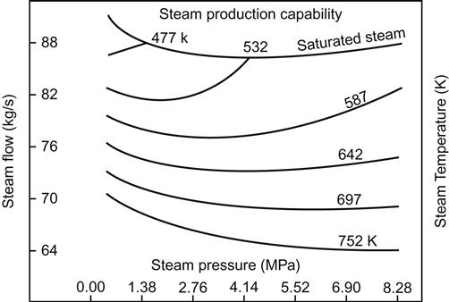
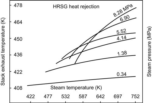
The “steam production capability” and associated “heat rejection through stack” of a typical HRSG are shown in Figure 7.30 and Figure 7.31, respectively, which were drawn based on the following inputs:
i. The gas turbine was firing 8.8 kg/s of fuel with 425.0 kg/s of air
ii. The HRSG was receiving exhaust gas from above gas turbine at a temperature of 862 K
7.6.1 Design
Temperatures available in the furnace of conventional steam generators by combustion of fuel are very high (1200–1500 K, depending on the type of fuel), while gas turbine exhaust temperatures upstream of HRSG are very low (673–823 K). The design of HRSG thus becomes critical since fall in its inlet gas temperature will affect the energy absorbed in various heat transfer surfaces, especially the economizer, and eventually the exit gas temperature from the HRSG. Hence, to determine the steam generation and to predict gas-steam profiles, an economic design of HRSG is ensured considering the following five key parameters:
The back-pressure is significantly influenced by the HRSG cross-sectional flow area. Higher back pressures reduce HRSG cost but also reduce gas turbine efficiency. Thus, from a techno-economic standpoint back-pressures that are typically maintained at HRSG inlet are 2.50–3.75 kPa.
The best place to locate the superheater would be in the hottest area of the gas path. Since, at this location, it would take the least amount of surface to exchange the maximum heat to generate the hottest steam at the highest pressure.
The superheat attemperator to desuperheat steam may be placed at the outlet of the superheater, or at an intermediate position in superheat heat exchange path. The intermediate position, however, has an added advantage of preventing accidental entry of water that may damage downstream equipment.
HRSG is generally designed for natural, “thermosiphon” circulation. A vertical-tube HRSG generating very high steam pressure, however, may be designed with forced circulation system. The water is distributed within an inlet header to various parallel circuits and the steam and water mixture is collected in an outlet header and returned to the drum for separation of steam and water.
An HRSG without supplementary firing is generally designed with a circulation ratio of 5:1. However, suffice it to say that one with supplementary firing may be designed with a lower circulation ratio of 3:1. Figure 7.32 depicts a simple, single-pressure HRSG with the usual disposition of superheater, evaporator, and economizer sections.

A detailed flow scheme of a dual-pressure cycle with deaerator is shown in Figure 7.33 that is comprised of an HRSG with two steam circuits, one high-pressure (HP) and one low-pressure (LP) circuit. While the HP steam feeds the HP turbine, the latter feeds the LP turbine.

Each of the circuits has its own economizer, steam drum, evaporator, and superheater. The exhaust gas leaving the gas turbine enters the HRSG. On passing through the HRSG gas exchanges its heat at various heat recovery sections, thereby getting cooled prior to leaving through the stack. The condensate extraction pump draws condensate from the condenser hotwell and then circulates the condensate through two closed-type feedwater heaters (FWH & CPH) and deaerator. From the deaerator feedwater storage tank one high pressure boiler feed pump (HFP) and one low pressure boiler feed pump (LFP) take their suctions. Feedwater line from LFP discharge after passing through a low pressure economizer enters the low pressure drum, followed by low pressure evaporator and low pressure superheater, wherefrom superheated steam is transported through the low-pressure steam turbine to deliver power. Similarly feedwater line from HFP discharge passes through the high-pressure economizer, steam drum, evaporator and superheater in that sequence. This superheated steam enters the high-pressure stage of the same steam turbine to boost power generation.
The pinch point temperature and approach temperatures have a significant impact on the overall unit size. While small pinch point and superheater approach temperatures result in larger heat transfer surfaces and higher capital costs, the economizer approach temperature is typically set to avoid the economizer steaming at the design point. Pinch and approach points are selected in unfired mode at design gas flow and inlet gas temperature conditions. Once they are assumed, the surface areas of the HRSG evaporator, superheater, and economizer are indirectly fixed or considered selected. Once selected, pinch and approach will vary with other conditions of gas flow and steam parameters.
The evaporator pinch is defined as the temperature difference between the flue gas leaving the evaporator and the saturation temperature of the fluid flowing through evaporator. The evaporator pinch limits the amount of heat that can be recovered in most HRSG designs. A pinch point of 28 K is generally considered for economic design of HRSG used in refineries and chemical plants. In a combined cycle or co-generation plants the pinch point is generally considered as 11 K, but could be as low as 5 K.
The economizer approach is the difference between the water temperature leaving the economizer and the saturation temperature of water. The “approach” of the economizer significantly affects the design and should be considered judiciously. This approach provides sufficient safety for load swings. Too low an approach may result in steaming in the economizer, which may upset the operation at certain operating conditions. Nevertheless, just because the economizer is steaming, does not necessarily mean it is a problem.
During the design stage itself the effect of steaming in the economizer could easily be overcome by taking the appropriate steps and factors. Most designs, however, are conservative and avoid this condition. In general, an average approach to the economizer is considered to be 11 K at the design stage, which is expected to ensure smooth, trouble-free operation. There are, however, many units in operation where the approach to the economizer is almost nil.
The higher the approach in superheaters, the less surface it will take to exchange heat. As a result, most of the flow in these sections is counter current to the gas flow, which provides a higher approach. For a lower approach steam flow through the superheater is usually cross flow to flue-gas flow. The absolute value of the superheater approach, however, does not affect the overall design of HRSG much.
The following ranges of pinch point and approach provide an economical and technically satisfactory design of HRSG, although a specific design may consider different values based on economical considerations:
The minimum flue-gas exit or stack temperature needs to be controlled to avoid corrosion due to acid condensation. In the event the exit temperature reaches or falls below the dew point of the flue gases resulting in formation of moisture film in the cold end, then such moisture formation may cause corrosion and fouling in that zone. These adverse conditions would exacerbate further if sulfur-bearing fuels are fired in gas turbines.
Example 7.4
A single-pressure HRSG, similar to Figure 7.32, receives 200 kg/s of flue gas from the exhaust of a gas turbine at a temperature of 800 K. The steam pressure and temperature at the HRSG superheater outlet are 4.25 MPa and 672 K, respectively. The feedwater temperature at the HRSG economizer inlet is 381 K. Determine:
i. Economizer pressure drop is 0.07 MPa
ii. Economizer approach is 11 K
iv. Superheater pressure drop is 0.10 mpa
v. Heat loss to atmosphere is 2% of heat available at inlet to each heat receiving section i.e., Superheater, evaporator, economizer, etc.
vi. Boiler drum blow-down is 2% of HRSG outlet steam flow
vii. Specific heat of flue gas at HRSG inlet is 1.10 kJ/kg/K
viii. Specific heat of flue gas at evaporator outlet is 1.07 kJ/kg/K
(Neglect pipe line losses.)
Solution: Let:
1. Economizer pressure drop be ΔP1 (=0.07 MPa)
2. Superheater pressure drop be ΔP2 (=0.10 MPa)
3. Economizer approach be ΔT1 (=11 K)
Based on these inputs the following table may be prepared:
| Parameter | Unit | Steam at superheater outlet | Feedwater at economizer inlet | Steam-water at boiler drum | Feedwater at economizer outlet | Flue gas at evaporator outlet |
| Pressure | MPa | 4.25 | 4.25+ΔP1+ΔP2=4.42 | 4.25 +ΔP2=4.35 | ||
| Temperature | K | 672 | 381 | 528.50 (Sat. temp.) | 528.50 – ΔT1=517.50 | 528.50 + ΔT2=556.50 |
| Enthalpy | kJ/kg | 3208.7 | 455.36 | hs=2798.6 | hwe=1058.5 | |
| hwd=1112.0 | ||||||

Heat rejected by flue gas between HRSG inlet and evaporator outlet:
Net heat available to superheater and evaporator considering 2% heat loss:
Considering 2% blow-down, the heat required by HRSG between the superheater and evaporator to generate steam,
Since HReq has to be equal to HNet,
Heat required at superheater:
Considering 2% heat loss, flue-gas temperature downstream of superheater, TSH, is:
The evaporator duty considering 2% blow-down:
Thus, the steam generated in the evaporator:
![]()
The economizer duty considering 2% blow-down:
Considering 2% heat loss, the flue-gas temperature downstream of the economizer, TECO, is:
7.7 Problems
7.1 An ideal simple cycle gas turbine takes in air at 300 K temperature and 101.3 kPa pressure. The combustor raises the gas temperature to 1100 K. Both the compression pressure ratio and the expansion pressure ratio are 4. Determine:
d. Energy lost in the exhaust gas
e. Inlet gas pressure to turbine
(Assume specific heat of air at constant pressure is 1.01 kJ/kg.K and γ is 1.4.)
(Ans.: (a) 147.26 kJ/kg, (b) 363.35 kJ/kg, (c) 26.74%, (d) 444.65 kJ/kg, (e) 405.2 kPa)
7.2 A simple cycle gas turbine operates between temperatures 1255 K and 293 K using helium as its working fluid. The isentropic efficiencies of the compressor and the turbine are 80% and 85%, respectively. The specific heat of helium is 5.2 kJ/ kg/ K and γ of helium is 1.66. Assuming both compression and expansion pressure ratios are 6, determine
a. temperatures around the cycle
c. Total heat to be supplied to generate 50 MW of power
(Ans.: T2=673.48 K, T4=711.46 K, η=28.04%, QTotal=178316.69 kJ/s)
7.3 A real Brayton cycle uses carbon dioxide as the working medium with polytropic efficiencies of the compressor and the turbine as 80% and 90%, respectively. A regenerator with 85% effectiveness is used in the cycle to improve the efficiency. The inlet and the maximum temperatures of the cycle are 313 K and 1323 K, respectively. Find the efficiency of this cycle considering the maximum output. Given: the specific heat of carbon dioxide is 0.87 kJ/kg/K and γ of carbon dioxide is 1.28.
(Ans.: η=39.98%)
7.4 A single-pressure HRSG receives 425 kg/s of flue gas from the exhaust of a gas turbine at a temperature of 862 K. The steam pressure and temperature at the HRSG superheater outlet are 5.5 MPa and 790 K, respectively, and the feedwater temperature at the HRSG economizer inlet is 400 K. While the fluid is flowing it suffers pressure drop across the superheater and economizer as 0.11 MPa and 0.09 MPa, respectively. If the economizer approach is 10 K and the evaporator pinch is 25 K, estimate the following neglecting any loss in the pipeline. (Assume the specific heat of flue gas at the HRSG inlet is 1.13 kJ/kg/K, and at evaporator outlet is 1.08 kJ/kg/K.)
a. Steam-generation capability of the HRSG
b. Flue-gas temperature downstream of superheater
d. steam generated in the evaporator
e. flue-gas temperature downstream of economizer
(Ans.: MSH=60.42 kg/s, TSH=776.68 K, HEV=99578.20 kJ/s, MEV=62.33 kg/s
TECO=487.31 K)
7.5 A dual-pressure HRSG, similar to the flow scheme in Figure 7.34 but with an integral deaerator, receives 315 kg/s of exhaust gas from a gas turbine at a temperature of 713 K. The high-pressure (HP) steam of 25 kg/s is generated from the HRSG at a pressure and temperature of 5 MPa and 693 K, respectively, while the intermediate pressure (IP) steam of 10 kg/s is generated at pressure and temperature of 0.5 MPa and 573 K, respectively. Each of the HP and IP circuits uses one superheater, one evaporator, and one economizer. Condensate is returned to the deaerator at a pressure and temperature of 0.6 M Pa and 327 K, respectively. To avoid corrosion at the cold end of the HRSG the exit flue-gas temperature is maintained no less than 405 K. Pressure drops of the working fluid at various sections of HRSG are as follows:
The “pinch points” at the HP, IP, and LP (deaerator) evaporators are 14, 10, and 12 K, respectively, while for the “economizer approach” it is 10 K at the HP circuit and 6 K at the IP circuit. Consider the average specific heat of gas is 1.07 kJ/kg/K. Neglecting any loss of working fluid from the cycle, calculate the temperature of the gas leaving each heat transfer surfaces. Neglect also temperature drop between:
1. HP superheater and HP evaporator
2. HP evaporator and HP economizer
3. HP economizer and IP superheater
4. IP superheater and IP evaporator

(Ans.: (a) 679.19 K, (b) 555.91 K, (c) 510.85 K, (d) 501.57 K, (e) 438.62 K, (f) 433.82 K.)