
Start-Up and Shut-Down
Start-up and shut-down of a thermal power plant comprises starting, running, and stopping of pumps, fans, blowers, compressors, etc., and charging, filling, warming, isolating of the miscellaneous piping systems. In this chapter start-up and shut-down of major equipment such as steam generator, steam turbine, gas turbine, and diesel engine are addressed. There are four types of start-up – cold, warm, hot, and very hot. There are two types of shut-downs: normal and emergency shutdown. Start-up and (normal) shut-down of a unit involve huge number of parallel activities that are realized through multiple actions by operators. To relieve operators from carrying out such arduous tasks, APS ensures automatic start-up and shut-down of a unit according to start-up/shut-down program by a single command by an operator.
Keywords
cold start-up; warm start-up; hot start-up; very hot start-up; normal shutdown; emergency shutdown; APS
12.1 Introduction
In addition to the steam generator and steam turbine, a thermal power plant essentially consists of equipment such as pumps, fans, blowers, compressors, etc., and systems of pipelines including valves, hangers, and supports. The start-up and shut-down of a unit thus comprises starting, running, and stopping of this equipment and charging, filling, warming, and isolating of the piping systems. Since covering all these activities in a single chapter is unrealistic, here we will focus on the start-up and shut-down of major equipment such as the steam generator, steam turbine, gas turbine, and diesel engine.
12.2 Start-Up of Steam Generator
12.2.1 Line-up of steam generator before start-up
Before the first start-up or start-up after overhaul the following activities/actions should be carried out or verified by operating personnel:
1. All works in boiler furnace have been completed
2. All works in air and gas ducts have been completed
3. Unit has been chemically cleaned
4. Steam lines have been blown
5. Safety valves on drum, superheater and reheater headers have been set
6. Boiler furnace, air pre-heaters, economizer, electrostatic precipitators, flue gas desulfurization (FGD) equipment, reduction of nitrogen oxides (DeNOx) equipment, induced draft (ID), forced draft (FD) and primary air (PA) fans, gas and air ducts are all cleared of men and foreign material
7. Boiler access doors, observation doors, and ash hopper doors are closed
8. Boiler drum manhole covers are properly seated
9. Boiler drum vent valves are open
10. Bottom ash hopper and hopper seal trough are filled with water; open the continuous make-up water to these hoppers and ensure proper overflow (this condition is applicable to a wet bottom ash system)
11. The following dampers are open:
a. Air heater air inlet/outlet
b. Air heater gas inlet/outlet
12. The following dampers are closed:
b. Pulverizer hot air shut-off gates
c. Pulverizer hot air control dampers
13. Secondary air dampers are open or modulating
14. Superheater start-up vent valves are in a partially open position
15. Superheater header manual vent valves and drain valves are open full
16. Reheater start-up vent valves are in partially open position
17. Reheater header manual vent valves and drain valves are open full
18. Superheater attemperator spray water supply block and control valves are closed
19. Reheater attemperator spray water supply block and control valves are closed
20. Boiler drum pressure and level transmitter are in operable condition
21. Isolation valves of boiler drum level gauge glasses and level transmitters are open and their blow-down valves are closed
22. Steam pressure gauge isolation valves and impulse line root valves are open
23. Feedwater, boiler drum water, saturated steam, and superheated steam sample line isolation valves are open
24. Chemical feed system inlet isolation valves to drum are open
25. Continuous blow-down line isolation valves are open and emergency blow-down line valves are closed
26. Continuous blow-down tank vent valve is open
27. Water wall drain header drain valves are closed
28. Drain valves at feedwater inlet to economizer inlet header are closed
29. Feedwater inlet valve to economizer inlet header is open
30. Coal feeder inlet and coal-bunker outlet gates are closed
31. Alarm annunciation system and data acquisition system (DAS) are available
12.2.2 Start-up
The sequence of start-up is as follows:
1. Start secondary regenerative air pre-heaters (if provided)
2. Start ID fans; verify that their inlet and outlet dampers open
3. Start FD fans; verify that their outlet dampers open
4. Adjust flow through ID fans and FD fans to permit a purge air flow of at least 30% of total air flow
5. Purge the furnace as discussed in Chapter 11
The steam generator is now ready for light-up.
12.2.3 Oil burner lighting
Lighting of oil burners includes the following:
i. Place all burner air registers to pre-light position
ii. Verify that burner atomizing valve is open
iii. Start the minimum number of oil burners
iv. Initiate light-up sequence of the lowest elevation of igniters and warm-up oil burners; oil burner is inserted
With insertion of oil burner, the following gas/electric igniter start sequence is initiated.
12.2.4 Gas igniter
i. At the start of the ignition sequence of a gas igniter, the igniter gas valve will open and a spark timer will energize. After a preset time period the igniter flame is checked.
ii. Should this flame be established, the main fuel oil shut-off valve and the burner fuel oil valve is signaled to open
iii. If burner oil flame is not detected at the end of the preset time period, the igniter gas valve and the burner fuel oil valve will close and an igniter fault will be signaled.
12.2.5 Electric igniter
i. At the initiation of the igniter start sequence, the igniter gets inserted and when the igniter is fully inserted a spark timer will energize
ii. When igniter energize signal is received, the main fuel oil shut-off valve and burner fuel oil valve will open; a trial (an ‘in-built checking circuit’) for ignition timer will operate, at the end of which the oil flame is checked
iii. If the burner oil flame is not established at the end of the preset time period, the oil burner shut-down sequence is initiated
If the oil flame is okay the following sequence is initiated:
12.2.6 Pressure raising
1. Regulate oil flow to increase the boiler water temperature and verify that the furnace exit gas temperature remains below 813 K in order to protect superheater, reheater, etc., through which coolant fluid flow is not yet established.
2. Gradually more oil guns are put into service according to the rate of pressure rise recommended by the boiler manufacturer
3. Check oil flame and stack; in a cold boiler the furnace tends to be smoky in the beginning, but it will clear up as the furnace warms up, however, the flame should be clear and bright. After adequate warm-up the stack should also be clear, and in no case should white smoke be allowed from the stack
4. Close the drum and superheater vent valves when a copious amount of steam issues out of them, at about 0.2 MPa drum pressure; close all the super heater drain valves; the starting vent valve should be kept partially open
5. Monitor drum metal temperature
6. Monitor the furnace exit gas temperature; in no case should it be more than 813 K to protect re-heater tubes, which have no cooling steam flow until now
7. Maintain drum level at normal (applicable to drum boiler)
8. Watch bottom ash hopper for proper overflow for removal of the accumulated unburned oil
9. With rise of steam pressure and flow it is necessary to feed water to boiler continuously
10. When steady flow of feedwater is established through the economizer, put the water side of the high-pressure feedwater heaters into service
11. Start PA fans; verify that their outlet dampers are open
12. Open coal feeder inlet and coal-bunker outlet gates
13. Start the pulverizer serving a lower elevation of coal nozzles
14. Open the hot-air shut-off gate and bring the pulverizer up to the required operating temperature (typically 343 K) as recommended by the boiler manufacturer
15. Maintain the fuel feed at minimum, consistent with stable ignition
16. Regulate hot and cold air dampers to hold pulverizer outlet temperature (typically 343 K) as recommended by the manufacturer
17. With increased firing rate, it may be required to open attemperator spray water
18. Ensure that air flow to the furnace corresponds to the firing rate at all times
19. Place additional pulverizers in service according to unit load demand
20. Remove fuel oil guns and igniters from service when unit-firing conditions are stabilized
21. Adjust feedwater supply to the boiler as required to maintain normal drum water level (applicable to drum boiler)
12.3 Normal Shut-Down of Steam Generator
When shutting down the steam generator, the reduction of the firing rate is determined by the reduction in the steam turbine steam demand:
1. Gradually reduce load on the unit, reduce the firing rate according to the decreasing steam flow.
2. Put the “combustion control” and “superheat and reheat temperature control” on manual.
3. When coal feeder rating on all pulverizers is reduced to 40% of MCR, start the fuel oil guns associated with the upper-most pulverizer in service.
4. Gradually reduce coal feeder rating further. When a minimum feeder rating of about 25% load is reached, close the hot air shut-off gate.
5. Close the superheater and reheater attemperator spray water supply block valves.
12.3.1 Controlled shut-down of pulverizer and coal-firing system
Controlled shut-down of the pulverizer and coal-firing system is accomplished as follows:
1. Reduce associated coal feeder speed to a minimum.
2. Close the associated hot air damper/gate.
3. When the pulverizer outlet coal-air temperature falls to a preset low limit (typically 323 K) as recommended by the manufacturer shut down the associated coal feeder.
4. Allow the pulverizer to run to ensure that it is completely empty by noting the load of the mill motor and shut it down.
5. When the coal feeder rating on all remaining pulverizers reaches 40%, take the second pulverizer, supplying the next higher elevation, out of service.
6. In the same manner continue taking out pulverizers at consecutive lower elevations.
7. When down to two pulverizers start the associated oil burners before reducing load on either of the associated coal feeders lower than 50% MCR.
9. Reduce the air flow according to the fuel reduction until 30% of maximum air flow is reached. Further lowering of air flow should only be done after fire-out of boiler.
10. After the last pulverizer has been shut down, remove fuel oil guns as discussed in the following.
12.3.2 Oil burner controlled shut-down
The shut-down sequence of the oil system may be initiated either “through burner stop command” or “by oil flame failure.”
ii. Open scavenging steam valve
iv. Verify burner scavenging is in progress
The shut-down sequence of the steam generator proceeds as follows:
1. Check and ensure all fuel to the furnace is cut off
3. Shut down ID fans, FD fans, and air heaters
4. Close superheater outlet shut-off valves
5. Open re-heater vent and drain valves
6. Stop chemical dosing to the drum
7. Maintain drum water level (applicable to drum boiler) near normal by adding feedwater as required
8. Take boiler feed pumps out of service
9. Maintain deaerator feedwater storage tank level near normal by adding condensate water as required
10. Take condensate extraction pumps out of service
11. Open drum vent valves and superheater vent and drain valves when drum pressure falls to 0.2 MPa
12. Boiler may be emptied when the water temperature falls below 368 K or to a value recommended by manufacturer
12.4 Emergency Shut-Down of Steam Generator
A variety of conditions can arise with steam generators, such as boiler steam/water tube rupture, that may require its shut-down.
12.4.1 Emergency shut-down of pulverizer and coal-firing system
Any pulverizer and coal-firing system should be shut-down on an emergency basis if:
i. Flame goes out in any two of four pulverized fuel burners in a group with the pulverizer running
ii. Pulverizer lubricating oil pressure is low
iii. MFR (master fuel relay) trips
v. Signal from preferential cut-out of mills as recommended by manufacturer
Emergency shut-down of pulverizer and coal-firing system will initiate:
12.4.2 Oil burner emergency shut-down
The oil burner shuts down automatically if:
ii. Oil header pressure is low
iii. Atomizing air/steam pressure is low
iv. Burner oil temperature is low (for heavy fuel oil-firing only)
The following sequence of activities will follow during the shut-down of the oil system:
The shut-down sequence of the steam generator proceeds as follows:
1. Stop pulverizers one by one and then oil burners
2. MFT should be operated manually without hesitation in case of any doubt about flame stability
3. Purge the furnace normally, if possible; if not possible, purge the furnace at the earliest opportunity
4. Keep ID fan/s running to maintain furnace in suction in order to prevent any pressurization due to tube rupture, etc.
5. Maintain drum level (applicable to drum boiler) at normal (Note: Do not feed water into drum, if the steam generator is tripped due to loss of drum water. Such feeding will cause damage to the furnace tubes.)
6. Cool steam generator as quickly as conditions permitted by the manufacturer
7. Proceed to normal shut down of the turbine and auxiliaries
12.4.3 Steam turbine stops/trips
In the event that the steam turbine stops or trips due to any trouble lying with steam turbine then it is not essential to stop the steam generator. Proceed as follows:
1. Shut down the steam generator and keep it boxed and bottled up so that it can be used on short notice
2. Do not reduce drum pressure
3. Close all superheater drain and vent valves; reheater vent and drain valves are left open
4. Close hot air shut-off gates to pulverizers
6. Stop pulverizers when they are empty
7. Verify that all fires are extinguished
8. Keep ID fans, FD fans, and air heaters running
9. As the unit cools down and the water shrinks, add make-up water intermittently to steam generator to prevent drum level from dropping below the visibility limit of the drum level gauge glass
12.5 Start-Up of Steam Turbine
Steam turbine start-up may be categorized as cold, warm, hot, and very hot start-up. This categorization follows industry practice based on the thermal conditions of steam turbines, usually the metal temperature of the HP turbine inner casing, at the time of start-up. It is also common in the industry to classify the start-ups on the basis of time since previous shut-down. The various categories of start-up are defined as follows (IEC 60045-1:1991: Steam Turbines Part-1: Specification and/or BS EN 60045-1:1993: Guide for Steam Turbine Procurement) [1,2].
12.5.1 Cold start-up
This category of start-up is usually followed after a 72-hour shut-down period of the steam turbine when the metal temperature of the HP turbine inner casing is expected to drop below approximately 40% of full-load metal temperature of the casing.
12.5.2 Warm start-up
Warm start-up is usually followed after a shut-down period of between 10 and 72 hours when the metal temperature of the HP turbine inner casing is between 40% and 80% of full-load metal temperature of the casing.
12.5.3 Hot start-up
Hot start-up is followed after a shut-down period of 10 hours. The metal temperature of the HP turbine inner casing is above approximately 80% of full-load metal temperature of the casing.
12.5.4 Very hot start-up
When a steam turbine is started within 1 hour after shut-down period, this is treated as very hot start-up. During this start-up, metal temperature of the casing remains at or near its full-load metal temperature.
12.5.5 Line-up of steam turbine before start-up
Before the first start-up or the start-up after a overhaul of steam turbines carry out or verify following activities/actions:
i. Steam generator has been started up and is ready for supplying steam to steam turbine
ii. Alternator, generator circuit breaker, generator transformer, excitation system, automatic voltage regulator, and associated electrical systems are ready for synchronizing with the grid
iii. Condenser cooling water inlet valves are closed
iv. Condenser cooling water outlet valves are open
v. Condenser water box vent valves are open
vi. Condenser support springs, if provided, are free
vii. Circulating water (CW) pumps are running
viii. Establish condenser cooling water system by opening CW pump discharge valves
ix. Slowly open condenser inlet valves to vent condenser water boxes
x. Close water box vent valves after water issues profusely through them
xi. Open steam turbine oil cooler cooling water inlet and outlet valves; establish cooling water flow through the coolers
xii. Check steam turbine main oil tank level is normal as recommended by the manufacturer
xiii. Check main oil tank level alarm-annunciations are active
xiv. Open suction and discharge valves of AC auxiliary oil pump and DC emergency oil pump. Prime these pumps by opening respective air vent valves
xv. Start auxiliary oil pump and gradually fill up bearing oil system and governing oil system
xvi. When the systems are filled-up, check oil level in main oil tank
xvii. Replenish oil into main oil tank to maintain normal level, if required
xviii. Verify pressure in lube oil system after oil coolers and at levels of bearing axis is adequate as recommended by the manufacturer
xix. Verify sufficient quantity of oil drains out from all bearings
xx. Verify temperature of lube oil is within permissible limits (313–318 K)
xxi. Switch off auxiliary oil pump
xxii. Check automatic starting of auxiliary oil pump and emergency oil pump
xxiii. Start jacking oil pump; put steam turbine on turning gear
xxiv. Check automatic tripping of turning gear at low lube oil pressure and at low jacking oil pressure per manufacturer’s guidance
xxv. Check the protection and governing system as follows:
a. Open emergency stop valve/s (ESVs) of HP turbine, interceptor valve/s (IVs) of IP turbine, and control valves of both HP turbine and IP turbine; check that their opening is smooth
b. Trip steam turbine manually through its shut-down switch and verify all above valves are fully closed
c. Normalize the turbine shut-down switch; ensure that no valves open again
d. Open emergency stop valve/s, interceptor valve/s, and control valves
e. Verify that emergency stop valve/s, interceptor valve/s, and control valves close on actuation of the turbine high axial shift
f. Verify that emergency stop valve/s, interceptor valve/s, and control valves close on actuation of turbine low bearing oil header pressure
xxvi. Put steam turbine on turning gear
xxvii. Place generator H2 cooling system, if provided, in service
12.5.6 Line-up of condensate system
i. Supply DM water and fill up condenser hot well up to 2/3 in the gauge glass
ii. Open inlet and outlet valves of low-pressure (LP) feedwater heaters; close bypass valves of LP heaters
iii. Open inlet and outlet valves of steam-air ejector, if provided
iv. Open suction valves of condensate extraction pumps (CEP); prime these pumps by opening respective air vent valves
v. Start one condensate extraction pump (CEP) with its discharge valve shut
vi. Slowly open discharge valve as the pump speeds up
vii. Open CEP common minimum flow recirculation control valve
viii. Supply sealing water to glands of all valves connected with vacuum service
12.5.7 Line-up of miscellaneous valves
i. Isolation valves of all pressure gauges are open
ii. Root valves of impulse lines, installed on steam lines, condensate line, oil lines, and cooling water lines, are open
iii. Emergency stop valve/s (ESV/s) of HP turbine is/are closed
iv. Interceptor valve/s (IV/s) of IP turbine is/are closed
v. Control valves of both HP turbine and IP turbine are closed
vi. Non-return valves at HP turbine exhaust are closed
vii. Non-return valves on turbine extraction steam lines are closed
viii. Drain/blow-down valves on main steam piping are closed
ix. Vent valves before HP bypass valve are closed
x. Drain/blow-down valves on cold and hot reheat piping are closed
xi. Drain valves for draining HP turbine casing are closed
xii. Before-seat drain valves and after-seat drain valves of non-return valves on turbine extraction steam lines are closed
xiii. Warm-up drain valves for emergency stop valve/s and control valves are open
12.5.8 Increase condenser vacuum
It is known from Chapter 9, Power Plant Systems, that evacuating air from the condenser may be realized either with the help of a steam jet air ejector or by utilizing a vacuum pump. Increase the condenser vacuum as detailed below:
In the event a steam jet-air ejector is used:
i. Slowly charge the ejector steam header and warm it up
ii. Start the steam-air ejector by opening its steam supply valve
iii. Open the isolating valves on air evacuating line connecting condenser and steam-air ejector
iv. As soon as the vacuum starts building up in the system apply the gland sealing steam, at a pressure slightly above atmospheric, to the front and rear gland seals of each of HP, IP, and LP turbines
v. Verify that the vacuum stabilizes or tends to stabilize at a level recommended by the manufacturer
ii. Open the isolating valves on air evacuating line connecting condenser and suction line of vacuum pump
iii. As soon as the vacuum starts building up in the system apply the gland sealing steam, at a pressure slightly above atmospheric, to the front and rear gland seals of each of the HP, IP, and LP turbines
iv. Verify that vacuum stabilizes or tends to stabilize at a level recommended by the manufacturer
12.5.9 Sequence of activities for cold start-up (follow Cold Start-up Curve as furnished or recommended by the manufacturer)
1. Open drain valves on main steam line/s
2. Open vent valves before HP bypass valves
3. Gradually open superheater outlet isolation valve/s
4. At the start of heating of main steam line/s condensed water will get drained, but gradually steam will come out through drain lines (that can be sensed by audible sound of steam escape), which indicates adequate warm-up of main steam line/s; close drain valves
5. When steam comes out through vent lines before HP bypass valves close vent valves
6. Gradually open HP bypass valve/s fully, ensuring that temperature control loop is functioning normally
7. Also ensure that LP bypass system is functioning normally
8. Open drain valves on cold reheat and hot reheat lines located as close as possible to steam turbine
9. Steam flow thus established through the bypass system and drain lines should assist in heating cold reheat and hot reheat lines
10. At the start of heating cold reheat and hot reheat lines condensed water will be drained, but gradually steam will come out through the drain lines, indicating adequate warm-up of cold reheat and hot reheat lines
11. Close drain valves; this should assist in increasing steam parameters
12. Once the main steam, cold reheat, and hot reheat lines are adequately warmed up increase the steam temperature at the steam generator outlet to a value higher than the minimum temperature requirement of the steam turbine as recommended by the manufacturer
13. Verify the H2 purity in generator, if provided, is above 94% or as recommended by the manufacturer
14. Put generator seal oil system, if provided, in service
15. Put generator stator cooling water system, if provided, in service
16. Verify that degree of superheat of main steam upstream of HP turbine is more than 50 K
17. Do not allow entry of steam into steam turbine until recommended matching of stem temperature is accomplished
18. Follow the manufacturer’s guidelines for matching steam-metal differential temperature
19. Open turbine casing drain valves
20. Open emergency stop valve/s (ESV/s) of HP turbine or verify that these valves open automatically through turbine start-up system
21. Open interceptor valve/s (IV/s) of IP turbine or verify that these valves open automatically through turbine start-up system
22. Admit steam to turbine and increase speed to predetermined value as per guidelines of the manufacturer for warming up of turbine casings
23. During warm-up and start-up of the steam turbine, observe following parameters remain at or within predetermined limits:
a. Steam-metal differential temperature
b. Differential temperature between upper and lower halves of turbine casing
c. Differential expansions of turbine
d. Bearing temperature and vibration
f. Operating parameters of condensing system
g. Operating parameters of turbine oil system
24. Maintain warm-up speed for soaking purposes
25. Once casings are warmed-up increase turbine speed and start rolling
26. Stop turning gear or verify that it stops automatically once turbine speed exceeds preset limit
27. Gradually increase the speed at a rate recommended by the manufacturer by allowing more steam to enter the steam turbine provided following parameters are within permissible limits:
a. Steam-metal differential temperature margin
b. Differential temperature between upper and lower halves of turbine casing
c. Differential expansion of casings
d. Bearing temperature and vibration
e. Turbine exhaust hood temperature
28. On reaching the rated speed leave the steam turbine for a recommended duration to ensure proper soaking of the turbine
29. Place automatic voltage regulator (AVR) on “auto”
31. Synchronize generator with the grid (this is discussed in detail under Section 11.7, Chapter 11, Interlock and Protection) and take a block load
32. Close drain valves of HP turbine casing
33. Close warming up drain valves for emergency stop valve/s and control valves
34. Open before-seat drain valves and after-seat drain valves of non-return valves on turbine extraction steam lines
35. Increase load at a predetermined rate
36. Open extraction steam supply block valves; place LP feedwater heaters in service
37. Increase main steam temperature and pressure following the manufacturer’s guidelines
39. Place HP feedwater heaters in service
40. Increase load at a predetermined rate to a load according to the system demand once the main steam temperature and pressure reach the rated values
41. Observe the following parameters remain at or within predetermined limits:
a. Differential expansions of turbine
b. Bearing temperature and vibration
d. Operating parameters of all associated systems, e.g., condensate, feedwater, extraction steam, and turbine lube oil, control oil, hydrogen, seal oil, stator cooling water, circulating water, etc.
12.5.10 Sequence of activities for warm start-up (follow Warm Start-Up Curve as recommended by the manufacturer)
1. Auxiliary equipment should be started in the same manner and order as for cold start-up
2. Check that all auxiliary equipment is working satisfactorily
3. Check the condition of all protections and interlocks
4. Ensure that the boiler has been lit and steam flow established through the HP-LP bypass system
5. Using the manufacturer recommended start-up curve increase the desired steam temperature and pressure for rolling the turbine
6. Admit steam to the turbine and start steam rolling
7. Observe the following parameters are within the permissible limits:
a. Steam-metal differential temperature
b. Differential temperature between upper and lower halves of turbine casing
c. Differential expansions of turbine
d. Bearing temperature and vibration
f. Operating parameters of condensing system
g. Operating parameters of turbine oil system.
8. Maintain warm-up speed for soaking purposes
9. Once casings are warmed up increase turbine speed and start rolling
10. Stop turning gear or verify that it stops automatically once turbine speed exceeds preset limit
12. Gradually increase the speed to the rated value at a rate recommended by the manufacturer by allowing more steam to enter the turbine, provided the following parameters are within the permissible limits:
a. Steam-metal differential temperature margin
b. Differential temperature between upper and lower halves of turbine casing
c. Differential expansion of casings
d. Bearing temperature and, vibration
e. Turbine exhaust hood temperature.
13. Place automatic voltage regulator (AVR) on “auto”
15. Synchronize generator with the grid and take a block load
16. Open extraction steam supply block valves; place LP feedwater heaters in service
17. Increase main steam temperature and pressure following manufacturer’s guidelines
19. Place HP feedwater heaters in service
20. Increase load at a predetermined rate to a load according to the system demand once the main steam temperature and pressure reach the rated values
21. Observe following parameters remain at or within predetermined limits:
a. Differential expansions of turbine
b. Bearing temperature and vibration
d. Operating parameters of all associated systems, e.g., condensate, feedwater, extraction steam, and turbine lube oil, control oil, hydrogen, seal oil, stator cooling water, circulating water, etc.
12.5.11 Sequence of activities for hot start-up (follow Hot Start-Up Curve as recommended by the manufacturer)
The procedure for hot start-up is similar to the procedure for warm start-up with the following differences:
1. Before rolling, the HP turbine inlet pressure and temperature will be much higher than those for warm start-up; from hot start-up curve determine the desired steam temperature and pressure for rolling the turbine
2. Admit steam to the turbine and start steam rolling
3. Observe the following parameters are within the permissible limits:
a. Steam-metal differential temperature
b. Differential temperature between upper and lower halves of turbine casing
c. Differential expansions of turbine
d. Bearing temperature and vibration
f. Operating parameters of condensing system
g. Operating parameters of turbine oil system.
4. Stop turning gear or verify that it stops automatically once turbine speed exceeds preset limit
6. Gradually increase the speed to the rated value at a rate recommended by the manufacturer by allowing more steam to enter the turbine provided following parameters are within permissible limits:
a. Steam-metal differential temperature margin
b. Differential temperature between upper and lower halves of turbine casing
c. Differential expansion of casings
d. Bearing temperature and vibration
e. Turbine exhaust hood temperature.
7. Place automatic voltage regulator (AVR) on “auto”
9. Synchronize generator with the grid and take a block load
10. Open extraction steam supply block valves; place LP feedwater heaters in service
11. Increase main steam temperature and pressure following manufacturer’s guidelines
13. Place HP feedwater heaters in service
14. Increase load at a predetermined rate to a load according to the system demand once main steam temperature and pressure reach rated value
15. Observe the following parameters remain at or within the predetermined limits:
a. Differential expansions of turbine
b. Bearing temperature and vibration
d. Operating parameters of all associated systems, e.g., condensate, feedwater, extraction steam, and turbine lube oil, control oil, hydrogen, seal oil, stator cooling water, circulating water, etc.
12.5.12 Sequence of activities for very hot start-up (follow Very Hot Start-Up Curve as recommended by the manufacturer)
The procedure for very hot start-up of steam turbine, as given below, is quite different from the previous three start-ups, since the metal temperature of the casing remains at or near its full-load metal temperature.
1. Before rolling, the HP turbine inlet pressure and temperature will be near to or at their rated conditions as per very hot start-up curve
2. Admit steam to the turbine and gradually increase the speed to the rated value at a rate recommended by the manufacturer by allowing more steam to enter the turbine, provided the following parameters are within the permissible limits:
a. Differential expansions of turbine
b. Bearing temperature and vibration
d. Operating parameters of all associated systems, e.g., condensate, feedwater, extraction steam, and turbine lube oil, control oil, hydrogen, seal oil, stator cooling water, circulating water, etc.
3. Stop turning gear or verify that it stops automatically once turbine speed exceeds preset limit
5. Place automatic voltage regulator (AVR) on “auto”
7. Synchronize generator with the grid and increase load at a predetermined rate to a load according to the system demand
8. Open extraction steam supply block valves; place LP feedwater heaters in service
12.6 Normal Shut-Down of Steam Turbine
1. Inform the boiler house that the turbine is being shut down
2. Ensure auxiliary oil pump and emergency oil pump are available and are ready for operation
3. Ensure the HP-LP bypass controllers are ON
4. Check for non-seizure of ESVs and IVs
5. Unload the turbine by gradually closing the control valves; the unloading should be carried out at a rate determined by the manufacturer’s guidelines
6. During unloading always keep watch on the following parameters to ensure they remain within the permissible limits:
i. Differential contractions of turbine, especially of HP rotor
iii. Steam-metal differential temperature margin
iv. Differential temperature between upper and lower halves of turbine casing
7. For minimizing the contraction of the HP rotor during shut-down admit main steam to HP front gland, if recommended by the manufacturer
8. Start the auxiliary oil pump and ensure that oil pressure in lube oil system is normal
9. Maintain lube oil temperature
10. After unloading the turbine to no load, trip the turbine manually
11. Ensure the ESV, IV, and control valves get closed
12. Ensure the extraction steam line block valves closed
13. Ensure the non-return valves at the HP turbine exhaust are closed
14. Ensure the generator is isolated through reverse power/low forward power relay
15. Verify that the field breaker is switched off
16. With the tripping of generator circuit breaker the HP-LP bypass system becomes operative; this may be used to stabilize boiler conditions and maintain steam flow through reheater until the boiler is shut down
18. When rotor speed falls to a predetermined low value, put the rotor on turning gear manually or turning gear may cut-in automatically. The rotor should remain on turning gear till temperature of HP casing falls below a recommended limit
20. Follow the manufacturer’s guidelines to open drain valves as follows:
ii. Before-seat and after-seat drain valves of non-return valves on turbine extraction steam lines
iii. Warm up drain valves for emergency stop valve/s and control valves
21. Close the HP-LP bypass valves
22. Stop the boiler firing per the recommendation of the boiler manufacturer and bottle up the boiler
23. Break the condenser vacuum once the fire in the boiler is killed
24. When the vacuum falls to zero, stop the gland steam supply
25. Stop the condensate extraction pump
26. The CW pump may be stopped when the temperature of the exhaust part of the LP turbine falls to 328 K or to a value recommended by the manufacturer
27. Open the drain valves on main steam piping
28. Open drain valves on cold and hot reheat piping
29. As the unit cools down and water shrinks, add make-up water intermittently to the boiler to prevent the drum level from dropping below the visibility limit of drum level gauge glass.
12.7 Emergency Shut-Down of Steam Turbine
An emergency shut-down of a steam turbine may become imminent due to variety of off-normal conditions either inside the steam turbine, such as unusual noise, etc., or in its associated equipment/systems, e.g., quality of stator cooling water deviating from its recommended limit.
1. Manually operate emergency trip push buttons
2. Ensure the ESVs, IVs, and control valves of both the HP and IP turbines get closed
3. Ensure the extraction steam line block valves are closed
4. Ensure the non-return valves at HP turbine exhaust are closed
5. Isolate the generator and switch off the field breaker
6. Make sure the HP-LP bypass valves have opened
7. Start the auxiliary oil pump and ensure the oil pressure in lube oil system is normal
8. Maintain the lube oil temperature
10. When the rotor speed falls to a predetermined low value, put the rotor on turning gear manually or turning gear may cut-in automatically
11. Break the condenser vacuum
12. Shut down the boiler and keep it boxed and bottled up
14. Following the manufacturer’s guideline open the drain valves as follows:
ii. Before-seat and after-seat drain valves of non-return valves on turbine extraction steam lines
iii. Warm up drain valves for emergency stop valve/s and control valves
iv. Drain valves on main steam piping
v. Drain valves on cold and hot reheat piping.
15. When the vacuum falls to zero, stop the turbine gland seal steam supply
16. Stop the condensate extraction pump
17. The CW pump may be stopped when the temperature of the exhaust part of the LP turbine falls to 328 K or to a value recommended by the manufacturer
18. The rotor should remain on the turning gear until the temperature of the HP casing falls below a recommended limit
20. As the unit cools down and water shrinks, add make-up water intermittently to the boiler to prevent the drum level from dropping below the visibility limit of the drum level gauge glass
21. Do not restart the boiler until identification and rectification of defects of turbine.
12.8 APS
From the previous discussion it is clear that start-up and (normal) shut-down of a large pulverized coal-fired unit involves a huge number of parallel activities that are realized through multiple actions by operators. In the process if any errors occur, due to erroneous operation and/or lack of proper understanding of sequence of operation, catastrophic damage to equipment, safety of the unit, loss of time, loss of generation, and as an ultimate loss of revenue could occur. To relieve operators from having to perform such arduous tasks, there is APS, a computer-aided start-up and (normal) shut-down system.
APS, which stands for automatic plant start-up and shut-down system, ensures the automatic start-up and shut-down of a unit according to start-up/shut-down program by a ‘single command’ by an operator. It reduces degree of operator error, start-up/shut-down time of each unit, and simultaneously enhances safety. APS is based on integrated unit-level-based control philosophy that can be achieved with minimum operator intervention.
If for some reason the APS sequence gets stalled the operator may either take the necessary corrective action or consciously bypass that step to ensure that the continuity of the start-up/shut-down process does not get impaired. However, operator intervention may be inevitable in the event of any or all of the following conditions:
i. Areas or equipment that cannot be automated
ii. On occurrence of spurious signal
iii. There is lack of required instrumentation
The APS sequence is conveniently hooked up to major equipment logic sequences, such as the burner management system, automatic turbine start-up system, sequential control system, balance of plant operating system, etc., such that APS appears as a stand-alone program for both the steam generator and the steam turbine and generator.
Before discussing the details of APS, it should be noted that it is not the first start-up of any plant. During the first start-up of a plant there are many areas that may operate in parallel and demand the special attention of the operating personnel. In these cases, more vigilance is needed to observe the individual or interactive behavior of the various systems and equipment before the sequence of activities may proceed.
In contrast, APS is executed in a step-by-step manner. It is like any “automatic control loop” that can be put into service once all associated systems had been started, trialed, tested, and stabilized. Thus, before initiating the APS program there are certain “prerequisite” conditions/areas that need to be handled by the operator.
Readers are advised to become familiar with the previous sections as well as the previous chapters to better understand the intricacies of APS.
12.8.1 Automatic start-up
The first step in the start-up program is to ensure that all prerequisites are established. It must be ensured that all associated systems, e.g., compressed air system, raw water system, DM water system, CW, ACW, and CCW systems, DCS, etc., are in service and stabilized. It must also be ensured that all associated electric power supply systems are in service and stabilized. Furthermore, since emergency power acts as back-up to power control centers, uninterrupted power supply systems (UPS), and DC distribution boards, the status of emergency power supply is also prerequisites to ensure that in the event of unit power failure the progress of the APS sequence will not get interrupted.
These conditions, nevertheless, do not initiate the start-up program. There are many more prerequisite conditions that need to be satisfied before issuing the start-up command. These prerequisites, as follows, are neither prioritized nor put in sequential order, but should all be fulfilled for automatic start-up to progress:
1. Firefighting system is ready to be put into service
2. Power receiving substation is energized
3. LT (415V) start-up switchgears are energized
4. Common power centers are energized
5. Water treatment switchgear is energized
6. Unit power centers are energized
7. Common distribution boards are energized
8. 125V DC distribution board is energized
11. Emergency DG and associated emergency switchgear are commissioned
12. Lighting and electric service power system is energized
13. Communication system is in service
14. Air-conditioning plant is in service
15. Generator step-up transformer is ready to be put into service
16. Unit auxiliary transformer is ready to be put into service
17. Generator circuit breaker is ready to be put into service
18. Switchyard substation is ready to be put into service
19. Excitation panel is energized
21. Alarm annunciation system and data acquisition system (DAS) are in service
22. Adequate storage of raw water is available
23. Adequate storage of DM water is available
24. Auxiliary steam is available at adequate pressure
28. Instrument air system is lined-up
29. Service air system is lined-up
31. Condensate system is lined-up
32. Feedwater system is lined-up
33. HFO system is lined-up and is ready to be put into service
34. Atomizing steam system is lined-up
35. Atomizing burner valves open and are ready to be put into service
36. Boiler superheater outlet stop valves are closed
37. Boiler superheater header drain valves are open full
38. Boiler reheater header drain valves are open full
39. Boiler waterwall header drain valves are open full
40. Boiler superheater outlet (SHO) vent valve is open full
41. Boiler reheater outlet (RHO) vent valve is open full
42. Feedwater inlet valve to economizer inlet header is open
43. Drain valves at feedwater inlet to economizer inlet header are closed
44. Drain valves on Main Steam piping are closed
45. Drain valves on Hot Reheat piping are closed
46. Drain valves on Cold Reheat piping are closed
50. Debris filter on CW supply pipe line to condenser is in service
51. Condenser on-load tube cleaning system is in service
52. Drum level (applicable to drum boiler) is maintained normal through auto-control
53. Deaerator feedwater storage tank level is maintained normal through auto-control
54. Hotwell level is maintained normal through auto-control
55. DMW transfer pump recirculation control valve is on auto
56. CCCW head tank DMW inlet control valve is on auto
57. CCCW header pressure control valve is on auto
58. Condensate transfer pump recirculation control valve is on auto
59. Condensate storage tank DMW inlet control valve is on auto
60. Turbine seal steam header supply control valve from auxiliary steam system is on auto
61. Turbine seal steam header drain control valve is on auto
62. HFO forwarding pump recirculation control valve is on auto
63. Atomizing steam pressure control valve near burner is on auto
64. Deaerator pressure control valve is on auto
65. CEP minimum flow recirculation control valve is on auto
66. BFP minimum flow recirculation control valve is on auto
67. Turbine lube oil (LO) pressure control valve is on auto
68. Turbine LO temperature control valve is on auto
69. Turbine control oil pressure control valve is on auto
70. Turbine control oil temperature control valve is on auto
71. Generator seal oil pressure control valve is on auto
72. Generator H2 pressure control valve is on auto
73. Feedwater low load control valve is on auto
74. Feedwater full load control valve is on auto
75. Auxiliary steam header pressure control valve is on auto
76. Auxiliary steam header temperature control valve is on auto
77. HP/LP bypass pressure control valve is on auto
78. HP/LP bypass temperature control valve is on auto
79. Turbine lube oil (LO) system is ready to be put into service
80. Turbine jacking oil (JO) system is ready to be put into service
81. Turbine control fluid system is ready to be put into service
82. Generator seal oil system is ready to be put into service
83. Generator H2 system is ready to be put into service
84. Generator stator cooling water system is ready to be put into service
85. HP turbine emergency stop valves are closed
86. HP turbine control valves are closed
87. IP turbine interceptor valve/s (IVs) are closed
88. IP turbine control valves are closed
89. Coal bunkers have enough storage of coal
[Note that the term “lined-up” appears in many places in this list. It essentially means that before initiating the sequence to progress the associated system/s must ensure free flow through it/them. Some examples of “lined-up” conditions are:
i. a valve that is to remain open (or closed) before initiating the sequence, then the status of this valve should be ensured by “open” (or closed) limit switch
ii. a damper that is to remain open (or closed) before initiating the sequence, then the status of this damper should be ensured by “open” (or closed) limit switch
iii. a storage tank from which fluid has to be taken to system, then it is to be ensured that level in this tank is adequate
iv. a sink, where the fluid will flow, must be in a position to receive the fluid
v. an electric power supply source must be in energized condition and be available whenever required, etc.]
Along with the prerequisites, the program determines the status of start-up condition (i.e., cold, warm, hot, or very hot start-up) in line with the guidelines described in Section 12.5 (and shown in Figure 12.1).

Depending on the type of start-up condition, some permissive conditions are either bypassed or may need to be repeated. Once all prerequisites are satisfied and the status of permissive condition is determined, the operator initiates the single “start-up sequence” command to the “APS start-up program” for it to advance automatically and thereby the main sequence is activated (Figure 12.2). As the program advances, it issues commands to various equipment to start and then checks back to determine whether the command was realized. If satisfied, the program advances further sequentially from the source of the DM water up to the loading of turbine.

The APS flow diagram of a typical pulverized coal-fired power plant is very complex and large in size, which is difficult to accommodate in a single chapter. Therefore, a general step-by-step automatic start-up sequence is given in Table 12.1 for simplicity. While preparing Table 12.1 the input criteria at many steps essentially resembles the check-back criteria of the previous step.
Table 12.1
Step-by-step sequence of automatic start-up of a unit


12.8.2 Automatic (Normal) shut-down program
For normal shut-down of a unit the turbine is unloaded first, and simultaneously the HP/LP bypass is operated. With the bypass in service once the turbine load is reduced to 60% (which is the stable load for boiler control) unloading of boiler takes place according to the load on the turbine and the opening of the HP/LP bypass valves. Once the turbine is fully unloaded, the boiler starts unloading to zero load.
As in case of the automatic start-up program certain “prerequisite” conditions, as follows, need to be fulfilled by operator action before initiating the shut-down command. This equipment may not remain in service during normal operation, but before initiating automatic (normal) shut-down of the unit, it must be available.
1. Turbine auxiliary oil pump is available
2. Turbine emergency oil pump is available
3. Turbine JO pump is available
(Note: During turbine shut-down, “below a certain turbine speed” the turning gear comes into service and remains in service till HP turbine casing temperature is above a low temperature limit as recommended by the manufacturer. The turning gear is stopped only when “HP turbine casing temperature falls below the recommended low limit.”)
The step-by-step sequence of the automatic (normal) shut-down of a typical pulverized coal-fired power plant is given in Table 12.2.
Table 12.2
Step-by-step sequence of automatic shut-down of a unit

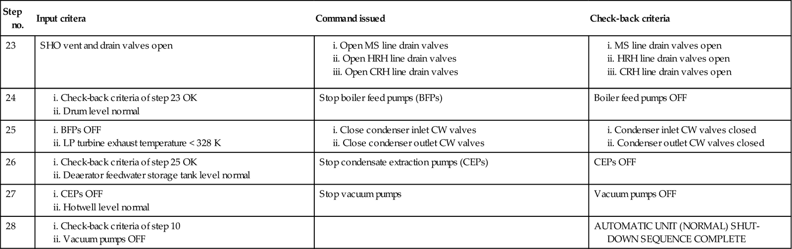
(Note: If the following equipment are installed ‘unit wise’ they may also be stopped at Step 25:
Instrument and service air compressors, CW pumps, and DMW pumps.)
12.9 Start-Up of Gas Turbine
The operation of a modern gas turbine is a fully automated process, with various auxiliaries of the turbine automatically switched in and out of operation in a sequential manner. There is no operator intervention required except for the selection of fuel and the setting of load. The operations take place step-by-step in a pre-set order.
12.9.1 Pre-start checks
Before starting the gas turbine, the following must be inspected and checked:
1. Gas turbine and its components are in a state of tidiness and no rags or tools are lying in or around them
2. Maintenance work (if any) on different parts of the unit has been completed and all permit to work cards have been returned by authorized maintenance personnel duly signed
3. Inspect all parts of the plant subjected to maintenance work and make sure that all maintenance personnel have been withdrawn and the plant is ready for start-up
4. “Danger” tags from valves and switchgears, if there be any, are removed
5. All relevant valves in fuel gas conditioning skid as well as fuel oil treatment system are open
6. Drain all drain points of fuel gas conditioning skid
7. Gas pressure at gas turbine fuel gas skid inlet is adequate
8. Oil pressure at gas turbine fuel oil skid inlet is adequate
9. Check that air intake filter house is free of accumulated water either by opening drain plugs or by visual inspection
10. Starting device is switched on
11. Turbine lube oil tank level is at normal or above
12. Lube oil pressure drop across strainers, filters, and also oil flow through sight glasses are within normal limit
13. Lube oil pressure is equal to or above the recommended value
14. All systems, i.e., fuel gas, fuel oil, lube oil, etc., are tight and no visible leakage exists
16. All control and power fuses are in place
17. Battery voltage and charging equipment are in order
18. All control and selector switches are in proper sequence for start-up program
19. Electrical control and protection systems are not isolated and are in service
20. Annunciations, instruments, all indicating lamps are healthy
21. Operation from control room is in order
22. Check that “generator transformer”, “unit auxiliary transformer”, various electrical boards and power supply systems, etc., are in `ready to operate” position
23. Auxiliary power supply is at the rated voltage and frequency
24. Fire-detection system and automatic CO2 fire-extinguishing system are in order
25. Portable fire extinguishers are in place around machinery space, fuel oil skid, fuel gas skid, etc.
Once these conditions are satisfied the gas turbine is purged with at least 8% of full-load mass air flow for a period of no less than 5 minutes. The gas turbine is now ready to start.
12.9.2 Start-up, Synchronizing, and Loading
Start-up of a gas turbine essentially means regulation of the fuel flow to the gas turbine at the initiation of a start signal. During this period the fuel/air ratio is maintained so the outlet gas temperature does not exceed permissible limits at maximum acceleration.
The typical gas turbine start-up and synchronization procedure is as follows:
1. Check that field breaker is OFF and AVR is operative
2. Ensure starting power from an external source
3. Gas turbine auxiliaries are thus placed in service
4. Gas turbine set is then accelerated with the help of starting device until the turbine is ignited and self-sustaining speed is reached
5. Governing system then takes over and accelerates the set to synchronous speed
6. After the machine has attained the synchronous speed, the synchronizing device adapts the turbine speed to match the grid frequency; the machine voltage is then brought to the rated value
7. While connecting to the grid, the parameters of frequency, phase angle, and voltage are adjusted to suit the grid; the generator is then synchronized with the grid by closing the generator circuit breaker.
12.9.3 Normal operation
During loading and subsequent operation of the machine, the primary responsibility of the operator is to observe and record the operational parameters of the main unit as well as its auxiliaries and ancillaries and to take corrective measures when required to control the machine. The operator must also keep a close watch on the performance of the generator exciter, AVR, and load regulator.
During start-up and normal operation, the following parameters should remain at or within the predetermined limits:
12.10 Normal Shut-Down of Gas Turbine
Before stopping the gas turbine unload the generator first and then initiate stop command. Normal shut-down of gas turbine is initiated by a stop signal resulting in total cut-off of fuel flow to the gas turbine.
12.11 Emergency Shut-Down of Gas Turbine
To protect the gas turbine from serious damage in the event of failure of open- and/or closed-loop control systems emergency shut-down of gas turbine is followed to shut-off the fuel supply to gas turbine without waiting for unloading the unit.
12.11.1 Unit cool-down and shut-down checks (normal or in the case of an emergency)
Immediately following a shut-down, the gas turbine should be put on barring gear for a period of predetermined time to assist in uniform cooling of the turbine rotor. Uniform cooling of the turbine rotor prevents rotor bowing and resultant rubbing and unbalance, which might otherwise occur on subsequent starting attempts.
The barring device is interlocked with a lubricating oil and jacking oil system and will not operate until the lube oil and jacking oil supply to the bearings is established. The minimum cool-down time depends on the ambient temperature and air draft. However, if the machine is not going to remain idle for a prolonged period, it is advisable that the barring operation be continued until a subsequent starting attempt is made.
The following checks have to be made after the machine is shut down:
i. Lube oil pump is maintaining good flow of oil at each bearing
ii. Battery charger voltage and current are normal
iii. Investigate any faults found during running
iv. Perform any repair/maintenance, as required
v. Open exhaust duct drain cock
12.12 Start-Up of Diesel Engine
12.12.1 Preparing the diesel engine for start-up during normal operation
Before the diesel engine is started the following checks/activities should be done:
1. Ensure there are no foreign objects on the diesel-generator and its accessories
2. Governor speed scale indicator pointer is in STOP position
3. Shaft barring arrangement is engaged with the shaft and locked in that position
4. All safety devices, lower crankcase, main drive, and drives for major accessories travel freely
5. Condition of joints and fastening of diesel engine auxiliary system pipelines is good; make sure that all cocks, valves, and flaps are in the operating position
6. Admit water to the external cooling circuit and make sure the water system joints are not leaking
7. Oil and fuel filters cut in for the operation of both sections
8. Check for the absence of water in the circulating oil tank and in the oil cooler (ensured by taking samples from the lower part of tank and cooler)
9. Bleed air out of the upper points of diesel engine cooling system, fill the system with internal circuit water, and pour oil and fuel into the respective systems up to the rated levels
10. Scavenge condensate out of starting air cylinders and charge them with air up to a pressure recommended by the manufacturer
11. Level of oil in the speed governor is up to the center of oil level indicator
12. Set the filter and cooler priming pipeline valve in the position for shutting off flow into the tank and ensuring priming of filter and cooler
13. Start automatic heating of oil and water
14. When warming up and priming the diesel engine with water, check the internal cooling circuit system for absence of leakage and also check the sealing of pipe unions, starting valves, injectors, etc.
15. Cocks on the receiver and exhaust manifold oil drain pipes are open and are not choked; clean pipes, if necessary
16. Engage in independent priming and scavenging oil electric pumps
17. Air pipeline valves should be closed and fuel feed limiter shut-off valve is open
18. Leave the electric pumps engaged, open indicator valves, prime the diesel engine with oil, and at the same time turn the crankshafts by means of shaft barring arrangement; check supply oil pressure to the diesel engine
19. While priming oil and cranking the diesel engine, check supply of oil to all the bearings, to the main drive and the drives for major and minor accessories; check flow of oil out of piston cooling pipes, and check also proper sealing of joints of oil pipelines in the engine crankcase, starting valves, and starting system
20. Having accomplished the check, close air pipeline valves, and open shut-off valves on the main starting valves
21. Prime the high-pressure fuel injection pumps and engine system
22. Supply air to thermo regulators; make sure that valves of thermo-regulators move smoothly and without jamming
The diesel engine is now ready for starting.
When the diesel engine is running, monitor the following parameters to ensure that they remain within their recommended limits:
ii. Temperature of exhaust gases in manifolds
iii. Engine oil inlet temperature
iv. Engine oil outlet temperature
v. Engine internal circuit water inlet temperature
vi. Engine internal circuit water outlet temperature
vii. Engine oil inlet pressure
viii. Engine internal circuit water inlet pressure
x. Pressure of external circuit water downstream of pump
xi. Pressure of air fed to thermo-regulators
xii. Level of oil in the circulating tank
xiii. Temperature of exhaust gases in the cylinders
xiv. Temperatures of bearings, stator winding, and rotor winding
12.13 Normal Shut-Down of Diesel Engine
Before stopping the diesel engine after its continuous rated-power operation, unload the generator first then initiate stop command. Once the stop command is initiated the engine speed is reduced to a value as recommended by the manufacturer. The engine continues to run at this speed until it is cooled down sufficiently. After the oil temperature drops to about 328 K the fuel supply to the engine is cut-off to bring down the speed to zero.
12.14 Emergency Shut-Down of Diesel Engine
Stopping a diesel engine in an emergency can be achieved, without cooling the engine, by initiating the emergency stop command and cutting the engine load. Right after the engine is stopped (normally or in the case of emergency), do the following:
a. Open cocks on the drain pipes of the receiver and exhaust manifolds
b. Make sure that water outlet temperature is within 303 and 323 K and the oil outlet temperature is within 313 and 323 K. If the temperatures are higher, prime water and oil systems using respective pumps until the required range of temperature is reached
c. Pump oil from the diesel engine sump and system scavenging pipeline into the circulating tank using a oil scavenging pump
d. Close the engine air supply pipeline valve and also the valve that admits air to the thermo-regulators