
Steam Power Plant Cycles
Thermodynamics deals with the conversion of one form of energy to another. In a thermodynamic cycle a fluid is returned to its initial state after transfer of heat/work across the system boundary. Laws of thermodynamics form the basis on which the whole foundation of thermodynamics is developed. The first law of thermodynamics states that heat and work are mutually convertible, and the second law of Thermodynamics states that work must always be less than heat. From the entropy of a fluid we can assess the degree of conversion of heat into work. The Carnot Cycle lays the foundation of second law of thermodynamics. The Rankine cycle calculates the maximum possible work that can be developed by an engine using dry saturated steam between the pressure limits of boiler and condenser. With the help of reheat-regenerative cycle the efficiency of a plant can be enhanced substantially. Other cycles of interest are the Kalina cycle, binary, vapor cycle, etc.
Keywords
system; boundary; cycle; work; heat; entropy; efficiency; reheat; regenerative; Kalina; binary vapor
1.1 Introduction
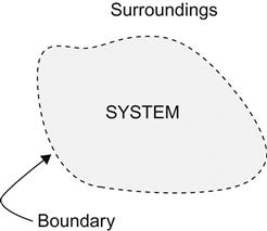
The science of thermodynamics covers various concepts and laws describing the conversion of one form of energy to another, e.g., conversion of heat energy into mechanical energy as in a steam or gas turbine or conversion of chemical energy into heat energy as observed during the combustion of fuel. The science of thermodynamics also deals with the various systems that are put into service to perform such conversions. A system in thermodynamics refers to a definite quantity of matter bounded by a specified region (Figure 1.1), where the transfer and conversion of mass and energy take place. A boundary is a surface that separates the quantity of matter under investigation from its surroundings. While the region may not be fixed in either shape or volume, the boundary either may be a physical one, as the walls of a pressure vessel, or it could be an imaginary surface [1,2].
There are two types of thermodynamic systems: open and closed. In an open system, mass enters or leaves through the system boundary (Figure 1.2) as in case of “steam flow through a turbine.” In the closed system, mass remains completely within the system boundary throughout the period of thermodynamic study and observation, as in the event of “expansion or compression of steam in a reciprocating steam engine.” In this system, there is no interchange of matter between system and surroundings. It is to be noted that in both open and closed systems, heat/work may cross the system boundary [1–4].

Thermodynamics also deals with the relations between properties of a substance and quantities of “work” and “heat,” which cause a change of state. Properties of a substance that describe its condition or state are characterized as pressure (P/p), temperature (T), volume (V/v), etc. These properties are measurable and depend only on the thermodynamic state and thus do not change over a cycle. From a thermodynamic point of view, the state of a system at any given moment is determined by the values of its properties at that moment [1,2,5].
When a system passes through a series of states in a process or series of processes in such a way that the final state of the system becomes identical to its initial state in all respects and is capable of repeating indefinitely then the system has completed a cycle [2]. The same principle is also followed in a thermodynamic cycle in which a fluid is returned to its initial state after the transfer of heat/work across the system boundary irrespective of whether the system is open or closed. However, heat and work are not zero over a cycle, they are process dependent. If the cyclic process moves clockwise around the loop producing a net quantity of work from a supply of heat, it represents a heat engine, and “work” will be positive. If the cyclic process moves counterclockwise, during which the net work is done on the system while a net amount of heat is rejected, then it represents a heat pump, and “work” will be negative [2].
A reservoir is a source of heat or a heat sink so large that no temperature change takes place when heat is added or subtracted from it. When heat from a reservoir is transferred to a working fluid circulating within a thermodynamic cycle mechanical power is produced. Thermodynamic power cycles are the basis of the operation of heat engines, which supply most of the world’s electric power and run almost all motor vehicles. The most common power cycles used for internal combustion engines are the Otto cycle and the Diesel cycle. The cycle used for gas turbines is called the the Brayton cycle, and the cycle that supports study of steam turbines is called the Rankine cycle.
A thermodynamic cycle is ideally be made up of any three or more thermodynamic processes as follows:
i. Isothermal (constant temperature) process
ii. Isobaric (constant pressure) process
iii. Isochoric (constant volume) process
iv. Adiabatic (no heat is added or removed from the working fluid) process
v. Isentropic or reversible adiabatic (no heat is added or removed from the working fluid and the entropy is constant) process
Table 1.1 shows some examples of thermodynamic cycles.
Table 1.1
Example of thermodynamic cycles
| Cycle/Process | Compression | Heat addition | Expansion | Heat rejection |
| External combustion power cycles: | ||||
| Carnot | isentropic | isothermal | isentropic | isothermal |
| Stirling | isothermal | isochoric | isothermal | isochoric |
| Ericsson | isothermal | isobaric | isothermal | isobaric |
| Internal combustion power cycles: | ||||
| Otto (Gasoline/Petrol) | adiabatic | isochoric | adiabatic | isochoric |
| Diesel | adiabatic | isobaric | adiabatic | isochoric |
| Brayton | adiabatic | isobaric | adiabatic | isobaric |

(Note: Details on internal combustion power cycles can be found in Chapters 7 and 8.)
In a simple steam power plant as the fluid circulates it passes through a continuous series of cyclic mechanical and thermodynamic states. Water enters a steam generator at a certain pressure and temperature and gets converted to steam, the high-pressure steam then enters a steam turbine and expands to a low pressure while passing through the turbine, the low pressure steam then gets condensed in a condenser, and the condensed water is recycled back to the boiler at original pressure and temperature (Figure 1.3) [6,7].

The performance of combined heat and power (CHP) generation steam power plants is determined by a term specific steam consumption (s.s.c.), which is defined as the mass flow of steam required per unit of power output (kg/kWh). The smaller the value of s.s.c., the bigger the plant size and vice-versa, e.g., for a CHP plant of 30 MW or lower capacity the value of s.s.c. is more than 4 kg/kWh, while for a utility plant of 250 MW or higher size the s.s.c. is close to or less than 3 kg/kWh. In utility power plants, however, the heat rate, defined as the energy required to be supplied to generate unit of power (kcal/kWh), is the best tool to determine the efficiency of the plant [7].
1.2 Laws of Thermodynamics
Before we further discuss thermodynamic cycles it is essential to cover the fundamental laws of thermodynamics on which science of thermodynamics is based. While studying the laws of thermodynamics it should also to be kept in mind that the science of thermodynamics deals with relations between heat and work only.
1.2.1 First law of thermodynamics
In a cyclic process, since the initial and final states are identical, the net quantity of heat delivered to the system is proportional to the net quantity of work done by the system. When heat and work are mutually convertible, we have the first law of thermodynamics. Mathematically speaking,
(1.1)
From Eq. 1.1 we can see that the first law of thermodynamics is an expression of the principle of conservation of energy. With the help of this law it is possible to calculate the quantities of heat and work that cross the surroundings of a system when given changes in properties occur. In a more generalized way the first law may be defined as when a system is taken through a cycle, the net work delivered to the surroundings is proportional to the net heat taken from the surroundings [2].
As a consequence of the first law, in addition to the pressure, temperature, and volume, another property exists in thermodynamics, such that any change in its magnitude is equal to the difference between the heat supplied and the work done during any change of state. This property is known as internal energy, denoted by U, and in a thermodynamic cycle change in internal energy (ΔU) is zero. If U1 represents the energy of the system at the beginning of a process, U2 its energy on completion of the process, Q the net heat flowing into the system in course of the process, and W the net work done by the system during the process, then the increase in energy of the steady-state open system having one inlet (subscript 1) and one exit (subscript 2), according to the first law of thermodynamics is expressed as [1,2,4]
(1.2)
Neglecting the effects of kinetic and potential energies Eq. 1.2 reduces to
(1.3)
Equation 1.3 reveals that when a system passes through a cyclic process U2=U1 and Q=W. Thus, the net heat flowing to the system equals the net work done by the system, and as a result it is impossible to construct a machine that would operate in a cycle. Consequently, the first law may be stated as it is impossible to construct a perpetual motion machine of the first kind [2]. [NOTE: The perpetual motion machine of the first kind is one, which once set in motion would continue to run for ever.]
Equation 1.3 also reveals that U2–U1 depends only on the end states and is independent of the process by which the system is taken from one state to the other. The entire science of thermodynamics is in conformity with this conclusion. Hence, in a process whose end states change infinitesimally, the change in the internal energy of the system may be expressed as dU, the change in heat flow as dQ, and the change in net work done as dW. Accordingly Eq. 1.3 changes to:
(1.4)
In a constant pressure process, as in steam power cycle, dW=pdV, where p is pressure and dV represents the change in volume of the system on completion of the process, Eq. 1.4 changes to
or,
(1.5)
Since p is constant, pdV=d(pV), therefore, Eq. 1.5 may be written as
or,
(1.6)
In thermodynamics the quantity (U+pV) occurs frequently, and is identified with a special property called enthalpy H.
Therefore,
(1.7)
Following the above expression of enthalpy, the specific enthalpy (enthalpy per unit mass), represented by h in thermodynamics, is expressed in a state of equilibrium as
(1.8)
Since u and pv are functions of the state of a system only, a change in enthalpy between two states depends only upon the end states, and is independent of the process.
For incompressible fluid or liquid undergoing infinitesimal change in end states the expression in Eq. 1.8 for an isentropic process changes to
(1.9)
Integrating Eq. 1.9 between state 2 and state 1 it is found that
(1.10)
1.2.2 Second law of thermodynamics
While the first law asserts that net work cannot be produced during a cycle without some supply of heat, the second law expresses that some heat must always be rejected during the course of a cycle. In its simplest form the second law states that “heat cannot, by itself, flow from lower temperature to a higher temperature.” One of the classical statements of the second law, as given by Kelvin–Planck, is “it is impossible to construct a system that will operate in a cycle, extract heat from a reservoir, and do an equivalent amount of work on the surroundings [2].” Another statement of the second law, as set forth by German physicist Rudolf Clausius, is “it is impossible to construct a system that will operate in a cycle, remove heat from a reservoir at one temperature, and absorb an equal quantity of heat by a reservoir at a higher temperature [2,8].”
It is clear from these statements that to have continuous output from a system, it is essential that there be transfer of heat across the system boundary at inlet and exit. Hence, it may be concluded that, “while the first law states that the net work can never be greater than the heat supplied, the second law goes further and says that work must always be less.” In other words, all heat input to a system cannot be utilized into work, and a part of this heat must be rejected, thereby involving a term called system efficiency.
Suffice it to say that work can be completely and continuously converted to heat, but heat cannot be completely and continuously converted to work, which means within a cycle heat is not entirely available to do work on a continuous basis. This unavailable energy, called anergy, has to be rejected as low-grade heat once the work has been done. The available energy, also known as exergy, on the other hand, is the work output obtainable from a certain heat input in a cyclic heat engine [5].
Consider a system that receives heat QH from a high-temperature (TH) heat source, rejects QC to a low-temperature (TC) heat sink, and generates work W while operating in a cycle (Figure 1.4).

Hence, it can be written that
(1.11)
or,
or,
(1.12)
Therefore, the cycle efficiency of the system is defined mathematically as η=Work done/Heat supplied:
or
(1.13)
Since both QH and QC are finite, the value of η must be less than 1, even when all processes involved are ideal and frictionless. Thus, it could be concluded from the second law that the efficiency of any cycle must be less than 100%.
From this discussion it is evident that “a heat cycle which produces work” comprises (i) a high temperature heat source, (ii) a low temperature heat sink, and (iii) a system producing work, e.g., a heat engine. Consequent to this it may be stated that it is impossible to construct a perpetual motion machine of the second kind. [NOTE: A perpetual motion machine of the second kind is one, which will produce work continuously, while exchanging heat with only one reservoir.] [2].
1.2.2.1 Concept of entropy
From the first law of thermodynamics it was found that there is a new property called internal energy. Likewise, the second law contains another new property, which is function of a quantity of heat, that shows the possibility of conversion of heat into work. This property is a thermodynamic quantity representing the unavailability of a system’s thermal energy for conversion into mechanical work, and is often interpreted as the degree of disorder or randomness in the system. The name of this property was coined in 1865 by Rudolf Clausius as entropy. Clausius introduced the concept of entropy to facilitate the study of fluids passing through a reversible process (Section 1.3). Any increase in this new property “entropy” lowers the availability of that energy for doing useful work. In a physical system, entropy provides a measure of the amount of thermal energy that cannot be used to do work [1,8,9].
From the entropy of a fluid we may assess the degree of orderly or disorderly motion of its molecules. While condensing steam the degree of order of its molecular motion increases, which in thermodynamics is interpreted as a decrease in the entropy of the fluid. Likewise, when heat is applied to a fluid, its molecules get more agitated, collisions become more frequent, and the degree of motion of molecules become more chaotic, resulting in an increase in entropy.
Entropy is not a physical phenomenon that would exist in reality; there is no physical instrument to measure entropy. On the contrary, it is calculated from the pressure and temperature of a fluid at a particular state. It is a thermodynamic property that determines the thermal energy that always flows spontaneously from regions of higher temperature to regions of lower temperature in the form of heat. Like internal energy, the entropy of a system is a function of its end states only [7].
In a Carnot cycle (Section 1.3) the total change in entropy is zero, but when heat flows from a hotter substance to a colder one, the hotter substance loses less entropy than the colder substance gains – thus total entropy increases. In thermodynamics, an increase in entropy is small when heat is added at high temperature and is greater when heat is added at lower temperature. Hence, in an isolated system the necessary condition for the equilibrium of a system is that its entropy is at its maximum. Thus, for maximum entropy there is minimum availability of heat for conversion into work and for minimum entropy there is maximum availability of heat for conversion into work. Therefore, the second law of thermodynamics may also be stated as “total entropy of an isolated physical system either increases or remains constant; and can never decrease [2].”
Entropy, S, is not defined directly, but rather by an equation giving the change in entropy of the system to the change in heat of the system or is defined by “the quotient of a quantity of heat divided by its absolute temperature.” For constant temperature, the change in entropy, ΔS, is defined by the equation ΔS=ΔQ/T, where ΔQ is the amount of heat absorbed in a thermodynamic process in which the system goes from one state to another, and T is the absolute temperature at which the process is occurring. Hence, in a process whose end states change infinitesimally, an “infinitesimal change in entropy is equal to an infinitesimal change in heat addition divided by the temperature at which the heat is supplied.” Mathematically the above relationship may be expressed as
(1.14)
Integrating Eq. 1.14
(1.15)
2 and 1 stand for final and initial states, respectively.
From Eqs. 1.14 and 1.15 we may note that for a adiabatic process dQ=0, dS=0 and for an isothermal process T=T2=T1 and Q=T (S2 – S1).
Combining Eq. 1.7 and Eq. 1.14,
or,
(1.16)
or, per unit mass
(1.17)
From this discussion it may be concluded that the science of thermodynamics comprises six properties of a fluid that describe its state: pressure (P/p), temperature (T), volume (V/v), specific internal energy (u), specific enthalpy (h), and specific entropy (s) [7].
1.3 Carnot Cycle
The Carnot cycle was invented by Nicholas Le′onard Sadi Carnot in 1824. It is an ideal cycle in which heat is taken at a constant higher temperature and rejected to a constant lower temperature. This cycle laid the foundation for the second law of thermodynamics and introduced the concept of reversibility. A reversible process is an ideal process, where the process traverses the same path during forward and backward travel. Both the fluid and its surroundings in a reversible process can be restored to their original states, and work and heat exchanged in one path is restored in the reverse path. In a reversible process, the entropy of the system remains unchanged throughout various states of the process.
All real processes, however, are irreversible, although the degree of irreversibility varies among processes. The irreversibility in a process is developed due to mixing, friction, throttling, heat transfer, etc. One irreversible process in a cycle causes the whole cycle to become irreversible. In an irreversible process, the total entropy of the system increases as the process continues.
In a Carnot cycle a working fluid takes in heat reversibly from a reservoir (heat source) at a constant higher temperature, T1, expands adiabatically and reversibly to a constant lower temperature, T2, gives up heat reversibly to a reservoir (heat sink) at T3 (= T2), and is then compressed reversibly and adiabatically to its original state T4 (= T1)
In P-V (Pressure-Volume) and T-S (Temperature-Entropy) diagrams (Figure 1.5) the cycle is represented by an area bounded by the following two isothermals and two adiabatic processes:
i. 1-2: Reversible adiabatic expansion
ii. 2-3: Reversible isothermal heat rejection

State 4 in Figure 1.5 refers to saturated liquid and state 1 refers to saturated vapor.
From Figure 1.5, it is evident that the changes in entropy during heat addition and heat rejection are equal in magnitude. Therefore, ![]() . Thus:
. Thus:
Heat added to the system
(1.18)
Heat rejected from the system
(1.19)
The net work output of the system
(1.20)
The efficiency of the Carnot cycle
or,
(1.21)
(1.22)
Equation 1.21 shows that efficiency of the Carnot cycle depends on the temperature of the heat source and heat sink only and is independent of the type of working fluid. The higher the temperature of the heat source the lower the temperature of the heat sink, i.e., the wider the temperature range, the more efficient the cycle. This cycle also establishes that this is the maximum achievable efficiency a heat engine may attain [9]. In a real cycle, however, cycle efficiency will be always lower than the Carnot cycle efficiency.
In practice, T2 can seldom be reduced below 298–303 K, which corresponds to a condenser pressure of 3.5 kPa. Because the temperature of the sink – e.g., atmosphere, river, ocean – i.e., the temperature of cooling water below 288 K, is rarely available and the temperature difference between the condensing steam and the cooling water, required for the heat transfer with a reasonable size of condenser, must be about 10–15 K. The maximum value of T1 is limited to the critical point temperature of 647 K. Thus, the maximum efficiency the Carnot cycle may attain is about 54%.
The Carnot cycle is thermodynamically simple, but it is extremely difficult to realize in practice, because the isothermal heat rejection must be stopped at state 3, then subsequent adiabatic compression of a very wet vapor needs to be carried out to restore it to its initial state 4. During compression, the liquid gets separated from the vapor and further compression of the fluid has to work with a non-homogeneous mixture. As such, none of the practical engines operate on this cycle. Nevertheless, the Carnot cycle is an excellent yardstick to compare various thermodynamic cycles on a theoretical basis. All practical cycles, nevertheless, differ significantly from the Carnot cycle.
Example 1.1
Using Figure 1.5, calculate the efficiency and exhaust steam quality of a steam cycle operating between 4 MPa and 10.13 kPa.
Solution: From the steam table the following values have been found corresponding to steam pressures 4 MPa and 10.13 kPa:
| Steam pressure | Fluid temperature K | hf kJ/kg | hfg kJ/kg | hg kJ/kg | sf kJ/kgK | sg kJ/kgK |
| 4.00 MPa | T2=523.33 | 1087.40 | 1712.90 | 2800.30 | 2.7965 | 6.0685 |
| 10.13 kPa | T1=319.09 | 192.89 | 2392.31 | 2585.20 | 0.6526 | 8.1466 |

The cycle efficiency is ηc=(T1 – T2)/T1)}*100=(204.24 / 523.33)×100=39.03 %
Using s1=s2 (Figure 1.5), it is found that at a condenser pressure of 10.13 kPa, dryness fraction at state 2, exhaust, is
Enthalpy at exhaust is h2=192.89 + 0.723*2392.31=1922.53 kJ/kg
Example 1.2
Consider the Carnot cycle of Figure 1.5 and calculate the heat transfers, net work output, cycle efficiency, and specific steam consumption (s.s.c), using steam operating between pressures 8 MPa and 9.6 kPa.
Solution: From the steam table the following values have been found corresponding to steam pressures 8 MPa and 9.6 kPa:
| Steam pressure | Fluid temperature K | hf kJ/kg | hfg kJ/kg | hg kJ/kg | sf kJ/kgK | sg kJ/kgK |
| 8.0 MPa | T2=568 | 1316.27 | 1441.80 | 2758.07 | 3.2061 | 5.7436 |
| 9.6 kPa | T1=318 | 188.42 | 2394.80 | 2583.22 | 0.6386 | 8.1647 |

Using s1=s2 and s3=s4 (Figure 1.5), it is found that at a condenser pressure of 9.6 kPa, dryness fraction at states 2 and 3 are as follows:
and
Hence, from h=hf +xhfg, we find
The net work output is
The heat transfer in the boiler is
The heat transfer in the condenser is
The cycle efficiency is
The above value may be verified from Eq. 1.21 as
(Theoretically the above two efficiency values should have been the same. A minor difference between these values is the result of the approximation taken in the decimal portion while calculating the former efficiency value.)
Since 1 kWh=3600 kJ, the specific steam consumption is
1.4 Stirling Cycle
Like the Carnot cycle the Stirling cycle is also a thermodynamic cycle that was invented, developed, and patented before the Carnot cycle in 1816 by Reverend Dr. Robert Stirling [9]. The P-V and T-S diagrams of an ideal Stirling cycle (Figure 1.6) include the following four thermodynamic processes:
i. 1-2: Reversible isothermal compression
ii. 2-3: Reversible isochoric heat addition

The working medium in a Stirling cycle is a gaseous matter, such as air, helium, hydrogen, etc., instead of water and steam. Like the Carnot cycle all the processes in an ideal Stirling cycle are reversible in nature, hence when the gas is heated the engine produces work or power and when work is supplied to the cycle it works as the refrigerator or the heat pump. When the processes in the Stirling cycle are reversed they act as cryogenerator and the cycle is used in the field of cryogenics to produce extremely low temperatures or to liquefy gases like helium and hydrogen.
1.5 Ericsson Cycle
The Ericsson cycle is another ideal thermodynamic cycle named after inventor John Ericsson, who designed and built many unique heat engines based on various thermodynamic cycles. In the P-V and T-S diagrams (Figure 1.7) the ideal Ericsson cycle is represented by an area bounded by following two isothermals and two isobaric processes:
i. 1-2: Reversible isothermal compression
ii. 2-3: Reversible isobaric heat addition

The Ericsson cycle does not use the vapor-compression cycle, since the vapor never returns back to liquid. Hence, this cycle does not find practical application in piston engines. This cycle, however, may find application in gas turbines.
Thermodynamically, all three cycles, i.e., Carnot, Stirling, and Ericsson cycles are identical in nature, since all of them work between constant temperature at heat source and constant temperature at heat sink. All are theoretically capable of attaining identical efficiency, working between similar hot and cold end temperatures if there are no losses. However, none of these cycles finds practical application in commercial engines.
1.6 Rankine Cycle
In a steam power plant supply and rejection of heat is more easily realized at constant pressure than at constant temperature. It was William John Macquorn Rankine, after whom the Rankine cycle is named, who first calculated the maximum possible work that could be developed by an engine using dry saturated steam between the pressure limits of the boiler and condenser. The simplest steam cycle using dry saturated steam as the working fluid has the following basic components (Figure 1.8):

The Rankine cycle is an ideal thermodynamic cycle involving the following processes:
i. Steam generation in boiler at constant pressure
ii. Isentropic expansion in steam turbine
iii. Condensation in condenser at constant pressure
iv. Pressurizing condensate to boiler pressure by isentropic compression
Figure 1.9 shows the Rankine cycle in P-V and T-S diagrams. This cycle assumes that all processes are reversible, i.e., all processes take place without any friction and heat transfers take place across infinitesimal temperature drops.

The following states/processes are represented in these diagrams:
• State 1: Condition of saturated vapor at temperature T1 and pressure p1.
• Process 1-2: The vapor then expands through the turbine reversibly and adiabatically (isentropicaly) to temperature at T2 and pressure at p2.
• The turbine generates power at a magnitude much higher than the power required by the boiler feed pump.
• State 2: The exhaust vapor is usually in the two-phase region at temperature T2 and pressure p2.
• Process 2-3: The low pressure wet vapor, at temperature T2 (=T3) and, being a two-phase mixture process, at constant pressure p2 (=p3), is then liquefied in the condenser into saturated water and reaches the state 3, thus minimizing the work required by the boiler feed pump.
• State 3: Condition of saturated liquid at temperature T3 and pressure p3.
• Process 3-4: The saturated water, at the condenser pressure p3, is then compressed reversibly and adiabatically (isentropically) by the boiler feed pump to sub-cooled liquid in the steam generator at pressure p4.
• As the fluid is liquid at this stage the pump requires little input energy.
• State 4: Condition of sub-cooled liquid at temperature T4 and pressure p4.
• Process 4-1: The sub-cooled liquid at state 4 is heated at constant pressure p4, in the “economizer” section of the steam generator, to a saturated liquid at state 5. The saturated liquid is further heated in the “boiler or evaporator” section of the steam generator to saturated vapor at constant temperature and constant pressure (being a two-phase mixture) to its initial state (T1 and p1).
Hence, looking at Figure 1.9 following equations can be derived:
Heat added in the steam generator
(1.23)
Heat rejected to the condenser
(1.24)
Work output of turbine
(1.25)
Work input to feed pump
(1.26)
Thus, net work output
(1.27)
Therefore the efficiency of the Rankine cycle is
or,
(1.28)
Comparing Eq. 1.22 and Eq. 1.28 it may be noted that while working between identical temperature limits, h1 and h2 in both the cycles are the same, but h4 and h3 in the Carnot cycle are much higher than h4 and h3 in the Rankine cycle. As a result (h1–h4) and (h2– h3) in the Carnot cycle are much smaller than those in the Rankine cycle. Thus, the Rankine cycle offers a lower ideal thermal efficiency for the conversion of heat into work than does the Carnot cycle. This conclusion is also evident from Example 1.2 and Example 1.4.
Example 1.4
Referring to Figure 1.9, calculate the net work output, cycle efficiency, and specific steam consumption (s.s.c) using steam operating between pressures 8 MPa and 9.6 kPa.
Solution: From the steam table the following values have been found, corresponding to steam pressures 8 MPa and 9.6 kPa:
| Steam pressure | Fluid temperature K | hf kJ/kg | hfg kJ/kg | hg kJ/kg | sf kJ/kgK | sg kJ/kgK | vf m3/kg |
| 8 MPa | T1=568 | 1316.27 | 1441.80 | 2758.07 | 3.2061 | 5.7436 | – |
| 9.6 kPa | T2=318 | 188.42 | 2394.80 | 2583.22 | 0.6386 | 8.1647 | 0.00101 |

Using s2=s1, it is found that at a condenser pressure of 9.6 kPa and dryness fraction at state 2 is as follows:
Hence, from h=hf +xhfg
Applying Eq. 1.9,

(since 1 kPa=0.0102 kg/cm2, 1 MPa=10.2 kg/cm2, 1 m2=10000 cm2 and 1000 mkgf=9.8 kJ).
Therefore,
The heat supplied is
The net work output is
The cycle efficiency is
The specific steam consumption is
1.6.1 Real rankine cycle
In an ideal Rankine cycle (Figure 1.9) both the compression in the boiler feed pump (process 3-4) and expansion in the turbine (process 1-2) take place isentropically (reversibly and adiabatically). Hence, the efficiency of the ideal Rankine cycle may be regarded as the highest efficiency achievable in practice with a straight condensing machine. However, in a real Rankine cycle (Figure 1.10) the efficiency that could be achieved is less than the efficiency of the ideal Rankine cycle, since none of the compression and expansion processes are isentropic. This is because these processes on completion are non-reversible causing entropy to increase during compression in boiler feed pump (the isentropic process 3-4s increases to process 3-4) as well as during expansion in turbine (the isentropic process 1-2s increases to process 1-2), which further results in an increase in power required by the boiler feed pump and decrease in power generated by the turbine.

The irreversibility in a real Rankine cycle is the result of irreversibility in the following areas:
ii. Pressure drop in steam and water piping, heat exchangers, bends and valves, etc.
iii. Friction in turbine blading and pump resulting in increase in entropy in both
Further, during the process 1-2, since the vapor is moist it starts condensing and water droplets hit the turbine blades at high speed, causing erosion and pitting. These water droplets are very harsh, particularly at the last few stages of a low-pressure turbine. Thus, the efficiency of the turbine starts reducing gradually. This problem is overcome by superheating the vapor at state 1, which will move to the right to state 1′ (Figure 1.9) and hence produce less wet vapor after expansion (state 2′). However, by superheating the heat addition process in the steam generator is no longer isothermal and the average temperature of heat reception lies somewhere between that corresponding to states 1 and 1′, i.e., between T1 and T1′.
In addition to the higher dryness fraction, another advantage of superheating the steam is that the efficiency of the real cycle will also increase, since the cycle receives heat at higher temperature. Improving cycle efficiency almost always involves making a cycle more like a Carnot cycle operating between the same high and low temperature limits. Nevertheless, the maximum possible temperature of steam in a thermal power plant is restricted by the strength of the available materials for boiler tubes or turbine blades.
The real superheat cycle is slightly different from the cycle shown in Figure 1.10. Although the liquid leaves the boiler feed pump at state 4, steam leaves the steam generator, in lieu of a state 1, at state 1′sg (not shown in the figure), and enters the turbine at a different state 1′t (not shown in the figure). Further, liquid leaving the boiler feed pump must be at a higher pressure (p4) than the steam-generator exit steam pressure (p1′sg), which also will have to be higher than the steam pressure at turbine inlet (p1′t) because of friction drops in the heat exchangers, feedwater heaters, pipes connecting boiler feed pump and steam generator, pipes connecting steam generator and turbine, bends, superheater outlet valves, turbine throttle valves, etc. [3].
There would also be heat loss from pipes connecting the steam generator and turbine, causing a drop in entropy from state 1′sg to state 1′t.
Example 1.5
Considering the isentropic efficiencies of the expansion process as 0.80 and the compression process as 0.85 calculate the cycle efficiency and specific steam consumption (s.s.c) of the steam cycle of Example 1.4. If the steam flowing through the turbine is 60 kg/s, find out the power output.
Actual expansion work is WEA=0.8*(2758.07 - 1812.09)=756.78 kJ/kg
and actual compression work is WCA=8.07/0.85=9.49 kJ/kg
Therefore, the net work output is Wo=756.78 - 9.49=747.29 kJ/kg
The enthalpy at state 4 now is h4=h3+WCA=188.42+9.49=197.91 kJ/kg
And the heat supplied is Q1=(2758.07 – 197.91)=2560.16 kJ/kg
The actual cycle efficiency is ηr=747.29/2560.16*100=29.19%
The specific steam consumption is s.s.c.=3600/747.29=4.82 kg/kWh
(Note: The results of Examples 1.2, 1.4, and 1.5, as presented in the following table, compares the performance of the Carnot, Ideal Rankine, and Real Rankine cycles of steam operating between 8 MPa and 9.6 kPa pressures. It is evident from the table that even though the Carnot cycle provides the highest cycle efficiency, its net work output is the least and the specific steam consumption is the highest.)
| Parameters | Carnot cycle | Ideal saturated rankine cycle | Real saturated rankine cycle |
| Heat Added, kJ/kg | 1441.80 | 2561.58 | 2560.16 |
| Cycle Efficiency, % | 44.01 | 36.61 | 29.19 |
| Net Work Output, kJ/kg | 634.76 | 937.91 | 747.29 |
| Specific Steam Consumption, kg/kWh | 5.67 | 3.84 | 4.82 |

1.6.2 Reheat rankine cycle
For large steam power plants it is vital to maximize thermal efficiency and minimize specific steam consumption. Hence, these plants operate on high-pressure and high-temperature steam cycles. However, the problem encountered by raising the turbine inlet pressure is that the steam coming out of the turbine (at state 2, Figure 1.10) is very wet. Water droplets accompanying steam impinge turbine blades and damage the blades severely, impairing the efficiency of the turbine.
For all practical purposes it is unwise to allow steam with dryness fraction less than around 88% to remain in the turbine [7], even though higher-grade low-pressure turbine blade materials may accept a lower dryness fraction.
Accordingly, with superheating alone, the turbine exhaust dryness fraction will not increase enough to restrict erosion of turbine blades. To prevent blade erosion and inefficient turbine operation, wet steam is sometimes extracted from the turbine from an intermediate stage and then passed through reheater, where steam becomes re-superheated and is returned to the next stage in the turbine for further expansion (Figure 1.11). The fundamental purpose of reheat is not to improve cycle efficiency but to reduce the moisture content of the vapor in the exhaust of the turbine. Nevertheless, with reheating the thermal efficiency of the cycle increases significantly as compared with non-reheat cycle.

In practice steam is extracted from high-pressure (HP) turbine exhaust, circulated to the boiler for re-superheating or reheating, and returned to the intermediate-pressure (IP) or low-pressure (LP) turbine for further work. Exhaust steam from the HP turbine is called “cold reheat” steam, while reheated steam coming out of the steam generator is known as “hot reheat” steam.
Reheating is best suited in high-pressure units since it provides low specific volume of steam, thereby reducing the overall surface area of the reheater along with a consequent reduction in capital expenditure.
From Figure 1.11, neglecting the work input to the boiler feed pump, the work done in reheat cycle is
(1.29)
The heat added in the steam generator
(1.30)
Therefore, the efficiency of the Reheat Rankine cycle is
(1.31)
(Note: It should be kept in mind that by increasing the turbine inlet steam temperature and accordingly the steam pressure the cycle efficiency will always increase.)
Example 1.6
Using Figure 1.11, calculate the ideal cycle efficiency and specific steam consumption (s.s.c.) of a reheat cycle operating between pressures 8 MPa and 9.6 kPa with a superheat temperature and reheat temperature of 773 K and 773 K, respectively. (Assume steam condition after first expansion as dry saturated and neglect work input to boiler feed pump.)
Solution: From the steam table we find h2=h1=188.42 kJ/kg (since the given condition is to neglect the work input to the boiler feed pump.)
In order to find the reheat pressure p4/p5, we refer to the steam table to find the saturation pressure corresponding to s3=s4. It is found that
Further,
In contrast to Figure 1.11 the expansion from state 5 to 9.6 kPa, i.e., state 6 of this example, is in the wet region. Hence at the turbine exhaust
The total heat added to the boiler is
and the total work output from turbine is
Therefore, the cycle efficiency is
The specific steam consumption is
1.6.3 Regenerative rankine cycle
Note from Figure 1.9 that the efficiency of the un-superheated cycle is less than the efficiency of the Carnot cycle, i.e., (T1–T2)/T1, because a certain portion of the heat supplied to the boiler is transferred to raise the feedwater temperature from T4 to T1 [10]. If this additional heat to the feedwater could be transferred reversibly from the steam part of the cycle, then the heat supplied to the boiler would be transferred to the feedwater at a temperature somewhere between T4 and T1. This cycle, where efficiency is raised as explained, is known as the regenerative cycle. In this cycle, a specified quantity of energy remains circulating within the cycle, and as a result, irreversibility in the process of mixing relatively cold water with hot steam gets reduced.
The purpose of regeneration or “stage bleeding” is to improve cycle efficiency, which in turn minimizes steam consumption and results in plant efficiency. This is realized by adding regenerative feedheating to the superheat-reheat cycle. Feedheating involves extracting a fraction of the steam flowing through the turbine from one or more positions along the turbine expansion and using heat in the steam to preheat the water in feedwater heaters prior to entering the boiler (Figure 1.12) [3,11,12].

Each unit of extracted steam does a certain amount of work in the turbine from throttle conditions to point of extraction and transfers the remainder of its heat to the feedwater, thus conserving the total heat, instead of losing part of the heat to the circulating water passing through the main condenser.
Figure 1.13 shows T-s diagram of a multistage feedheating system, which shows that the heat addition to the cycle is reduced from the area bounded by 4′-4-4″-5-1-1′-2-2′-4′ to the area bounded by 3′-3-4″-5-1-1′-2-2′-3’ by adopting regenerative feedheating, i.e., the heat addition to the cycle is reduced by the area 4′-4-4″-3-3′-4′, keeping the output unchanged, thereby reducing the cost of power generation.
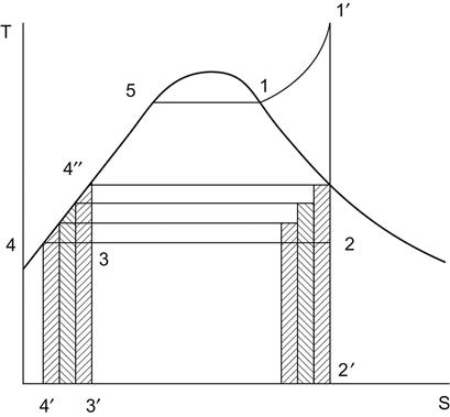
Figure 1.14 and Figure 1.15 show a typical triple-extraction three-stage feedheating regenerative cycle [2].


The ideal cycle efficiency of the above feedheating cycle (see Figure 1.15) is given by
(1.32)
Example 1.7
Calculate the ideal cycle efficiency and specific steam consumption (s.s.c.) of a regenerative cycle with triple extractions, as shown in Figure 1.14 and Figure 1.15, with boiler outlet steam pressure and superheat steam temperature are 8 MPa and 773 K, respectively, and condenser pressure 9.6 kPa. If the steam flowing through the turbine is 100 kg/s, also find the power output. Determine the heat rate of the turbine, which is defined as “the heat required at the turbine inlet per unit of power generated.” (Assume the turbine extraction bleed steam pressures such that temperature difference between T2 and T9 (Figure 1.15) is approximately equally divided. Neglect work input to boiler feed pump. Also assume that on completion of regenerative feedheating, the enthalpies of both the compressed feedwater and condensed steam are equal to the enthalpies of the saturated liquid corresponding to the respective extraction bleed steam pressures.)
Solution: From the steam table it is noted that at 8 MPa, the temperature at T2 is 568 K and corresponding to 9.6 kPa, temperature at T9 is 318 K.
For approximately equal temperature difference ((568–318)/4=62.5 K) among (T2–T13), (T13–T15), (T15–T17) and (T17–T9), the turbine extraction bleed steam pressures are chosen as 2.8 MPa, 0.8 MPa, and 0.12 MPa.
In order to facilitate solving this problem the following table has been prepared based on the given data and assumptions:
| Steam pressure | Temperature K | Inlet/ext. steam entropy kJ/kgK | Enthalpy kJ/kg | Dryness fraction % | |||
| Inlet/ext. steam | Saturated fluid | Inlet/ext. steam | Sat. steam | Sat. water | |||
| 1 | 2 | 3 | 4 | 5 | 6 | 7 | 8 |
| 8.00 MPa | 773.0 | 568.0 | s4=6.7262 | h4=3398.80 | h3=2759.90 | h2=1317.1 | – |
| 2.80 MPa | 608.0 | 503.0 | s5=6.7262 | h5=hEX1=3086.20 | 2802.00 | h13=990.48 | – |
| 0.80 MPa | 456.0 | 443.0 | s6=6.7262 | h6=hEX2=2797.40 | 2767.50 | h15=720.94 | – |
| 0.12 MPa | 378.0 | 378.0 | s7=6.7262 | h7=hEX3=2467.2 | 2683.40 | h17=439.36 | x7=90.363 |
| 9.60 kPa | 318.0 | 318.0 | s8=6.7262 | h8=2125.4 | 2583.40 | h9=188.50 | x8=80.878 |

This table is also reflects the following:
Column 2 shows temperature at different extraction bleed steam stages and at the exhaust of the turbine
Temperature of saturated liquid is shown in column 3
Isentropic expansion is given in column 4
Enthalpies of vapor at the inlet, extraction bleed steam stages and at the exhaust of the turbine are given in column 5
Enthalpies of saturated vapor and liquid at various pressures are presented in columns =6 and 7, respectively
Dryness fractions of wet vapor at the last extraction bleed steam stage and at the exhaust of the turbine are given in column 8
Let us denote the turbine extraction bleed steam flow quantity to feedheaters per kg of steam supplied to the turbine as ya, yb, and yc and give the extraction steam from each feedwater heater as EX1, EX2, and EX3 and the states of condensed steam/drain from each feedwater heater as D1, D2, and D3, both in decreasing order of pressure.
As per the given conditions and assumptions, we have h1=h13, hD1=h12=h14=h15, hD2=h11=h16=h17, and hD3=h9=h10=h18.
Using the energy equation for each heater, we get the following relationships:


Having found the turbine extraction bleed steam flows, it is possible to calculate the heat and work transfers for the cycle.
Heat added to the boiler is
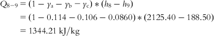
Heat rejected in the condenser is
Net work output is
Therefore, the cycle efficiency is
The specific steam consumption is
The power output is
Neglecting pressure drop in steam pipeline, it may be assumed that “heat required at the turbine inlet” is same as “heat added to the boiler.”
The heat rate of the turbine is
1. There are two types of feedwater heaters: open or direct contact feedwater heater and closed (contact less) feedwater heater. Two terms that are always used for heat transfer in closed feedwater heater are terminal temperature difference (TTD) and drain cooler approach (DCA) as defined below:
TTD=Saturation temperature of extraction bleed steam to the heater−Feedwater temperature at heater exit.
DCA=Heater extraction bleed steam condensate drain temperature−Feedwater temperature at heater inlet.
2. The results of Examples 1.4, 1.5, 1.6, and 1.7, as presented in the following table, compare the performance of the Ideal Saturated Rankine, Real Saturated Rankine, Ideal Superheat Reheat Rankine, and Ideal Superheat Regenerative Rankine cycles, with steam operating between 8 MPa and 9.6 kPa pressures.
| Parameters | Ideal saturated rankine cycle | Real saturated rankine cycle | Ideal superheat reheat rankine cycle** | Ideal superheat regenerative rankine cycle** |
| Heat Added, kJ/kg | 2561.58 | 2560.16 | 3931.18 | 2408.32 |
| Cycle Efficiency, % | 36.61 | 29.19 | 40.86 | 44.18 |
| Specific Steam Consumption, kg/kWh | 3.84 | 4.82 | 2.24 | 3.38 |

** In these cycles “work input to boiler feed pump” as well as “isentropic efficiencies of expansion and compression processes” have been neglected.)
Example 1.8
For the same cycle of Example 1.7 consider the following and calculate the cycle efficiency, specific steam consumption, power output, and heat rate of the turbine.
Isentropic efficiencies of expansion and compression processes as 0.9 and 0.8, respectively
Work input to boiler feed pump to be taken into consideration
Assume TTD for the lowest pressure heater as 3 K and for the remaining heaters as −2 K. DCA for all the heaters as 5 K
Neglect pressure drop in feedwater pipe, steam pipe, and extraction pipelines
Solution: For 0.9 isentropic efficiency for the expansion process and for 0.8 isentropic efficiency for the compression process all states on the vertical line of Figure 1.15 show that states 5, 6, 7, 8 and 10 would move toward the right. Hence, various thermodynamic parameters of these states will have new values as presented in the following tables:
| States | Steam press. | Enthalpy, kJ/kg | Inlet/ext. steam entropy kJ/kgK | Specific volume m3/kg | Dryness fraction x % | |||
| Isentropic inlet/ext. steam | Actual inlet/ext. steam | Sat. steam | Sat. water | |||||
| 4 | p2=8.00 MPa | h4=3398.80 | h4=3398.80 | h3=2759.90 | h2=1317.1 | s4=6.7262 | – | – |
| 5 | 2.80 MPa | 3086.20 | h5=hEX1=3117.46 | 2802.00 | h13=990.48 | s5=6.7771 | – | – |
| 6 | 0.80 MPa | 2797.40 | h6=hEX2=2857.54 | 2767.50 | h15=720.94 | s6=6.8546 | – | – |
| 7 | 0.12 MPa | 2467.2 | h7=hEX3=2560.36 | 2683.40 | h17=439.36 | s7=6.9729 | – | x7=94.515 |
| 8 | p9=9.60 kPa | 2125.4 | h8=2252.74 | 2583.40 | h9=188.50 | s8=7.1263 | vf9=0.00101 | x8=86.195 |
| s9=s10=0.6388 | ||||||||

| States | Steam press. | Temperature K | Enthalpy, kJ/kg | ||||
| Inlet/Ext. steam | Sat. fluid | Applying given TTD | Applying given DCA | Feedwater at 8.00 MPa | Heater drain | ||
| 4 | P2=8.00 MPa | T4=773.0 | T2=568.0 | – | – | h2=1317.1 | – |
| h10=196.56 | |||||||
| 5 | 2.80 MPa | T5=621.0 | T13=503.0 | T1=501.0 | T14=T12 + 5=446.0 | h1=982.09 | h14=733.33 |
| 6 | 0.80 MPa | T6=481 | T15=443.0 | T12=441.0 | T16=T11 + 5=386.0 | h12=714.43 | h16=474.48 |
| 7 | 0.12 MPa | T7=378 | T7=T17=378.0 | T11=381.0 | T18=T10+5=323.0 | h11=458.62 | h18=209.35 |
| 8 | p9=9.60 kPa | – | T8=T9=318 | – | – | h9=188.50 | – |

Using the energy equation for each heater as in Example 1.6, we get the following results:


Having found the turbine extraction bleed steam flows, it is possible to calculate the heat and work transfers for the cycle.
Heat added to the boiler is
Heat rejected in the condenser is
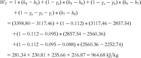
Work output of turbine
Work input to feed pump is

(since 1 kPa=0.0102 kg/cm2, 1 MPa=10.2 kg/cm2, 1 m2=10000 cm2 and 1000 mkgf=9.8 kJ).
Net work output is
Therefore, the cycle efficiency is
The specific steam consumption is
The power output is
The heat rate of the turbine is
(Note: The following table gives a comparison of the results of Examples 1.7 and 1.8:
| Example no. | FEX1 kg | FEX2 kg | FEX3 kg | ηr % | s.s.c. kg/kWh | P kW | HR kJ/kWh |
| 1.7 | 0.114 | 0.106 | 0.086 | 44.18 | 3.38 | 106411 | 8147.61 |
| 1.8 | 0.112 | 0.095 | 0.088 | 39.50 | 3.77 | 95460 | 9113.93 |

The above table shows that the performance of the real cycle, i.e., Example 1.8 is influenced by the factors “work input to boiler feed pump” and “isentropic efficiencies of expansion and compression processes,” resulting in reduction in cycle efficiency and power output and increase in specific steam consumption and turbine heat rate. Nevertheless, performance of this cycle does indicate substantial improvement in performance compared with the performance of the ideal saturated Rankine cycle.)
Figure 1.16 shows a typical steam-water flow diagram of a superheat-reheat-regenerative cycle.

1.7 Kalina Cycle
The Kalina cycle, named after the Russian engineer Alexander Kalina, is a thermodynamic cycle for converting thermal energy to mechanical power. The working fluid in this cycle is a mixture of at least two different fluids (typically water and ammonia). Ammonia has a lower boiling point compared with water. Hence, when the temperature of the mixture increases, the ammonia will boil first. In contrast to this when the mixture is cooled, water will condense first (Figure 1.17) [13,14]. When the mixture begins to boil at 550 kPa (state 3) the concentration of ammonia is 70% and water is 30%. As the boiling of mixture continues, the temperature increases and at state 4 the concentration of the remaining fluid and vapor formed are given by states 6 and 5, respectively. On further boiling of the mixture, when it reaches state 7, the mixture is saturated vapor. The concentration of vapor at this point is the same as the concentration of the liquid at the beginning of the evaporation process.

Unlike the Rankine cycle, where considerable heat energy is lost in the isothermal vaporization of water to steam, the binary mixture in the Kalina cycle vaporizes non-isothermally, resulting in better performance. Variable temperature boiling permits the working fluid to maintain a temperature closer to that of the combustion gases in the boiler. The use of mixture as the working fluid allows manipulating pressure in the system by changing composition of the mixture. At given cooling conditions the pressure in the condenser can be reduced to slightly above atmospheric pressure by decreasing the ammonia concentration of the condensing fluid. Increasing the ammonia concentration may raise the evaporation pressure. A high ammonia concentration causes a steep increase in pressure. The demands of high ammonia concentration in the working fluid during evaporation and expansion and low ammonia concentration during condensation are met by the distillation and mixing processes.
High temperature exhaust from any process/equipment, e.g., a gas turbine, is the heat source of the ammonia-water mixture for recovering heat [15]. By absorbing heat the mixture vaporizes and then drives the turbine. On partial completion of expansion in the turbine, the mixture gets condensed. The condensed mixture is further diluted to lower its pressure and extract more work from the turbine. Finally, this diluted working fluid is re-concentrated and sent back to the heat source. However, this cycle is not commercially viable, since it is difficult to handle large quantities of ammonia safely and reliably.
| Boiling Point at 101.3 kPa | 239.5 K |
| Melting Point | 195 K |
| Critical Point | 11.28 MPa and 405.4 K |
| Latent Heat of Vaporization at 101.3 kPa | 1371.2 kJ/kg |
| Vapor Pressure at 294 K | 888 kPa |
| Liquid Density at Boiling Point | 682 kg/m3 |
| Gas Density at Boiling Point | 0.86 kg/m3 |
| Gas Density at 101.3 kPa and 288 K | 0.73 kg/m3 |
| Liquid/Gas Equivalent at 101.3 kPa and 288 K | 947 vol/vol |
| Gas Specific Gravity at 101.3 kPa and 294 K | 0.597 |
| Gas Specific Volume at 101.3 kPa and 294 K | 1.411 m3/kg |
| Liquid Specific Heat Capacity (constant pressure) at 300 K | 4.75 kJ/kg.K |
| Gas Specific Heat Capacity (constant pressure) at 101.3 kPa and 288 K | 0.037 kg/mol.K |
| Gas Specific Heat Capacity (constant volume) at 101.3 kPa and 288 K | 0.028 kg/mol.K |
| Liquid Thermal Conductivity at 300 K | 477×106 kW/m.K |
| Gas Thermal Conductivity at 101.3 kPa and 273 K | 22.19 mW/m.K |
| Gas Solubility in Water at 101.3 kPa and 273 K | 862 vol/vol |
| Gas Auto-ignition Temperature | 903 K |
1.8 Binary Vapor Cycle
It is known that the higher the temperature of the heat source, the greater the cycle efficiency. Thus, a considerable improvement in cycle efficiency could be achieved provided evaporation takes place at a temperature corresponding to the metallurgical limit of the turbine. There is, however, a constraint. Although steam has a relatively low critical temperature (647.14 K), its critical pressure is very high (22.12 MPa). As a result, the design becomes critical. The process could be simplified if there is a working fluid whose critical temperature is higher than the metallurgical limit of about 873 K, but the vapor pressure of the fluid is moderate [2]. One such working fluid is mercury, with a vapor temperature of 873 K at a saturation pressure of only 2.3 MPa. It is evident that at a comparable temperature the saturation pressure of mercury is far below that of water.
Figure 1.18 and Figure 1.19 [2] show a cycle where mercury in conjunction with steam is used in a binary cycle to harness the benefit of the whole temperature range beginning with the metallurgical limit down to the atmosphere. In a mercury boiler mercury is evaporated and then it expands in the mercury turbine to a pressure of about 10 kPa. The mercury condenser then serves the dual purpose of condensing mercury and acting as a steam generator. Feedwater heating and superheating of steam after evaporation are performed by the heat of condensation of mercury vapor.


From Figure 1.19 it is observed that dry saturated vapor of mercury leaves the mercury boiler at state 10 and expands isentropically in the mercury turbine to state 11. A two-phase mixture of mercury vapor-liquid then enters the “mercury condenser-water boiler” heat exchanger to exchange its heat of condensation to water steam and reaches state 7. Then the mercury pump raises its pressure to state 8 for further evaporation in the mercury boiler.
Water becomes dry saturated vapor in a “mercury condenser-water boiler” at state 4 and then passes through the superheater in the mercury boiler furnace to state 5. Superheated steam then enters the steam turbine, expands isentropically to state 6, and condenses to state 1. Saturated water thereafter is pushed to the boiler to repeat the cycle.
Although quite attractive, this cycle is not commercially viable since it suffers from the following disadvantages:
i. Mercury vapor is toxic and extremely hazardous.
ii. At the normal heat sink temperature of about 300 K, the vapor pressure of mercury is extremely low and its specific volume is very large. Thus, the vacuum to be maintained in the mercury condenser is exorbitantly high, causing the size of the condenser to be impracticably large.
iii. Mercury has low latent heat (about one-eighth of the latent heat of steam), therefore, specific mercury consumption is high.
| Boiling Point at 101.3 kPa | 630 K |
| Freezing Point | 234 K |
| Latent Heat of Vaporization at 101.3 kPa | 272.1 kJ/kg |
| Latent Heat of Fusion at 101.3 kPa | 11.3 kJ/kg |
| Vapor Pressure at 373 K | 0.0364 kPa |
| Density at 373 K | 13352.2 kg/m3 |
| Specific Heat Capacity (constant pressure) at 273 K | 0.139 kJ/kg.K |
| Thermal Conductivity at 273 K | 7.82 W/m.K |
1.9 Problems
1.1 Steam expands in a Carnot cycle from 6 MPa pressure to 10.13 kPa pressure in the condenser. Calculate the cycle efficiency and specific steam consumption of the process.
(Ans.: ηc=41.83 %; s.s.c.=5.48 kg/kWh.)
1.2 Assume isentropic efficiencies of expansion and compression as 0.9 and 0.8, respectively, and calculate the cycle efficiency and specific steam consumption of the process of problem 1.1.
(Ans.: ηc=31.81 %; s.s.c.=7.20 kg/kWh.}
1.3 Calculate the heat and work transfers of a Carnot cycle, using steam between pressures 3 MPa and 8.67 kPa.
(Ans.:
Heat supplied to the cycle, Q2-3=1793.90 kJ/kg
Heat rejected from the cycle, Q4-1=1118.22 kJ/kg.s
Net work output of the system, Wo=675.68 kJ/kg)
1.4 Calculate the heat and work transfers of an ideal saturated Rankine cycle, using steam between pressures 3 MPa and 8.67 kPa.
(Ans.:
Heat added in the steam generator, Q1=2619.00 kJ/kg
Heat rejected to the condenser, Q2=1761.32 kJ/kg
Work output of turbine, WT=860.70 kJ/kg
Work input to feed pump, WP=3.02 kJ/kg
Net work output of the system, Wo=857.68 kJ/kg
Efficiency of the cycle, ηr=32.75 %)
1.5 Steam at a rate of 80 kg/s expands through an ideal saturated Rankine cycle turbine at temperature 623 K and condenses to a temperature of 313 K. Calculate the efficiency of the cycle.
(Ans.: ηr=38.94 %)
1.6 Assume isentropic efficiencies of expansion and compression as 0.85 and 0.75, respectively, and calculate the cycle efficiency and specific steam consumption of the process of problem 1.5.
(Ans.: ηr=32.84%; s.s.c.=4.61 kg/kWh)
1.7 Steam is generated at a pressure of 2 MPa and is then superheated to a temperature of 623 K. If this superheated steam is used in an engine working on ideal Rankine cycle, and expanded to a pressure of 10.33 kPa, calculate the thermal efficiency of the cycle and the dryness fraction of the steam after expansion.
(Ans.: x2=0.842; ηr=31.55 %)
1.8 Calculate the power output and the heat rate of a real superheat-reheat Rankine cycle turbine, through which 200 kg/s of steam at pressure and temperature of 13 MPa and 723 K, respectively, expands to a pressure of 3.5 MPa with an isentropic efficiency of 0.90, gets reheated to temperature of 753 K, and thereafter expands further with an isentropic efficiency of 0.85 to condenser pressure of 11.87 kPa. The saturated water is then compressed to pressure 13 MPa with an isentropic compression efficiency of 0.80.
(Ans.: P=248144 kW; HR=10188.70 kJ/kWh)
1.9 In an ideal superheat steam Rankine cycle turbine operating with four stages of feedheating, steam enters at pressure 10 MPa and temperature 673 K and condenses at pressure 8.66 kPa. Feedwater heating extraction bleed steam pressures are such that the difference between the saturated temperature at 10 MPa and the saturated temperature at 8.66 kPa is approximately equally divided. Assume isentropic efficiency of expansion as 0.8. Assume any other conditions that may be required to find the cycle efficiency, power output, and heat rate of the turbine. Neglect the work input to the boiler feed pump.
(Ans.: Assumptions:
i. Steam flow through turbine 100 kg/s
ii. Isentropic efficiency of compression as 1.0
iii. On completion of regenerative feedheating, the enthalpies of both compressed feedwater and condensed steam are equal to the enthalpies of saturated liquid corresponding to respective extraction bleed steam pressures.
ηr=36.22%; P=71614 kW; HR=9940.29 kJ/kWh)
1.10 A steam cycle operates between pressures 3.0 MPa and 4.0 kPa, and uses a superheat temperature of 723 K. The mercury cycle operates between pressures 1.4 MPa and 10 kPa, and the mercury is dry saturated prior to entering the turbine. Determine the cycle efficiency of this binary vapor cycle.
(Assume quantity of steam in circulation is 1 kg and quantity of mercury in circulation is y kg. Neglect the work supplied to the feed pumps.
Given: Referring to Figure 1.19
h10=362.55 kJ/kg, h8=h7=34.33 kJ/kg, x11=0.7286, h11=248.93 kJ/kg)
(CLUE: Sequence of calculations is to be as below:
i. First, calculate the heat and work transfers in the steam-water cycle.
ii. Perform the same calculations for the mercury cycle.
iii. Use the energy equation of the mercury condenser-steam generator as y*(h7 – h11)=1*(h4 – h3).)