7.7. NUMERICAL METHODS FOR UNSTEADY-STATE MOLECULAR DIFFUSION
7.7A. Introduction
Unsteady-state diffusion often occurs in inorganic, organic, and biological solid materials. If the boundary conditions are constant with time, if they are the same on all sides or surfaces of the solid, and if the initial concentration profile is uniform throughout the solid, the methods described in Section 7.1 can be used. However, these conditions are not always fulfilled, in which case numerical methods must be used.
7.7B. Unsteady-State Numerical Methods for Diffusion
1. Derivation for unsteady state for a slab
For unsteady-state diffusion in one direction, Eq. (7.1-9) becomes
Equation 7.7-1
![]()
Since this equation is identical mathematically to the unsteady-state heat-conduction Eq. (5.10-10),
Equation 5.10-10
![]()
identical mathematical methods can be used for solving both diffusion and conduction numerically.
Figure 7.7-1 shows a slab of width Δx centered at point n, represented by the shaded area. Making a mole balance of A on this slab at the time t when the rate in − rate out = rate of accumulation in Δt s,
Equation 7.7-2
![]()
Figure 7.7-1. Unsteady-state diffusion in a slab.

where A is cross-sectional area and t+Δtcn is concentration at point n one Δt later. Rearranging,
Equation 7.7-3
![]()
where M is a constant.
Equation 7.7-4
![]()
In using Eq. (7.7-3), the concentration t+ΔtCn at position n and the new time t + Δt is calculated explicitly from the known three points at t. In this calculation method, starting with the known concentrations at t = 0, the calculations proceed directly from one time increment to the next until the final time is reached.
2. Simplified Schmidt method for a slab
If the value of M = 2, a simplification of Eq. (7.7-3) occurs, giving the Schmidt method:
Equation 7.7-5
![]()
7.7C. Boundary Conditions for Numerical Methods for a Slab
1. Convection at a boundary
For the case where convection occurs outside in the fluid and the concentration of the fluid outside is suddenly changed to ca, we can make a mass balance on the outside half-slab in Fig. 7.7-1. Following the methods used for heat transfer to derive Eq. (5.4-7), we write rate of mass entering by convection − rate of mass leaving by diffusion = rate of mass accumulation in Δt hours:
Equation 7.7-6
![]()
where tc1.25 is the concentration at the midpoint of the 0.5 Δx outside slab. As an approximation, using tc1 for tc1.25 and rearranging Eq. (7.7-6),
Equation 7.7-7
![]()
Equation 7.7-8
![]()
where kc is the convective mass-transfer coefficient in m/s. Again, note that M ≥ (2N + 2).
2. Insulated boundary condition
For the insulated boundary at f in Fig. 7.7-1, setting kc = 0 (N = 0) in Eq. (7.7-7), we obtain
Equation 7.7-9

3. Alternative convective equation at the boundary
Another form of Eq. (7.7-7) to use if N gets too large can be obtained by neglecting the accumulation in the front half-slab of Eq. (7.7-6) to give
Equation 7.7-10
![]()
The value of M is not restricted by the N value in this equation. When a large number of increments in Δx are used, the amount of mass neglected is small compared to the total.
4. Procedure for use of initial boundary concentration
For the first time increment, we should use an average value for 1ca of (ca + 0c1)/2, where 0c1 is the initial concentration at point 1. For succeeding times, the full value of ca should be used. This special procedure for the value of ca increases the accuracy of the numerical method, especially after a few time intervals.
In Section 5.4B, concerning numerical methods for heat-transfer, a detailed discussion is given on the best value of M to use in Eq. (7.7-3). The most accurate results are obtained for M = 4.
5. Boundary conditions with distribution coefficient
Equations for boundary conditions in Eqs. (7.7-7) and (7.7-10) were derived for the distribution coefficient K given in Eq. (7.7-7) being 1.0. When K is not 1.0, as in the boundary conditions for steady state, Kkc should be substituted for kc in Eq. (7.7-8) to become as follows (see also Sections 6.6B and 7.1C):
Equation 7.7-11
![]()
Also, in Eqs. (7.7-7) and (7.7-10), the term ca/K should be substituted for ca.
Other cases, such as for diffusion between dissimilar slabs in series, resistance between slabs in series, and so on, are covered in detail elsewhere (G1), with actual numerical examples being given. In reference (G1) the implicit numerical method is discussed.
EXAMPLE 7.7-1. Numerical Solution for Unsteady-State Diffusion with a Distribution CoefficientA slab of material 0.004 m thick has an initial concentration profile of solute A as follows, where x is distance in m from the exposed surface:
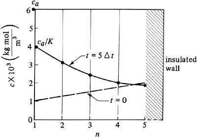
The diffusivity DAB = 1.0 × 10⁻⁹ m2/s. Suddenly, the top surface is exposed to a fluid having a constant concentration ca = 6 × 10⁻³ kg mol A/m3. The distribution coefficient K = ca/cn = 1.50. The rear surface is insulated, so that unsteady-state diffusion is occurring only in the x direction. Calculate the concentration profile after 2500 s. The convective mass-transfer coefficient kc can be assumed as infinite. Use Δx = 0.001 m and M = 2.0. Solution: Figure 7.7-2 shows the initial concentration profile for four slices and ca = 6 × 10⁻³. Since M = 2, substituting into Eq. (7.7-4) with Δx = 0.001 m and solving for Δt,
Figure 7.7-2. Concentrations for numerical method for unsteady-state diffusion, Example 7.7-1.
Hence, 2500 s/(500 s/increment) or five time increments are needed. For the front surface, where n = 1, the concentration to use for the first time increment, as stated previously, is Equation 7.7-12
where 0c1 is the initial concentration at n = 1. For the remaining time increments, Equation 7.7-13
To calculate the concentrations for all time increments for slabs n = 2, 3, 4, using Eq. (7.7-5) for M = 2, Equation 7.7-14
For the insulated end at n = 5, substituting M = 2 and f = n = 5 into Eq. (7.7-9), Equation 7.7-15
For 1 Δt or t + 1 Δt, the first time increment, calculating the concentration for n = 1 by Eq. (7.7-12),
For n = 2, 3, and 4, using Eq. (7.7-14),
For n = 5, using Eq. (7.7-15),
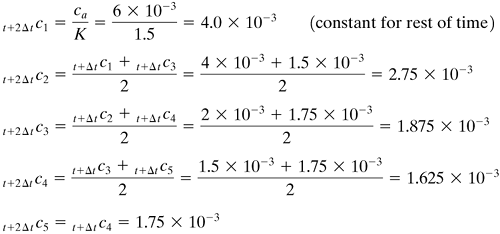
For 2 Δt, using Eq. (7.7-13) for n = 1, using Eq. (7.7-14) for n = 2–4, and using Eq. (7.7-15) for n = 5,
For 3 Δt,
For 5 Δt,
The final concentration profile is plotted in Fig. 7.7-2. To increase the accuracy, more slab increments and time increments are needed. This type of calculation is suitable for use with a computer spreadsheet. |


