
In previous chapters, you focused on the Azure Data Factory features and learned how to build an end-to-end pipeline. The focus of this chapter will be how to set up a pipeline flow and why it’s important for any organization.
Why Managing Flow Is Important
So far, you can build an Azure Data Factory pipeline and run it. This chapter will discuss expressions, functions, and activities to control the data flow in an ADF pipeline. Why do you need to manage the flow? An SSIS developer knows the importance of control flow; however, if you are new to this world, then let’s look at an example. As a data developer, you build an ADF pipeline to move data from an on-premises SQL Server instance to an Azure SQL Database instance. However, you are asked to move five tables now and six tables later. So, you will create one pipeline and change it later. This will continue as many times as the organization needs data for certain tables. Another example could be you have been asked to move delta/incremental data. This is not a straightforward flow. You need to tweak the ADF pipeline without changing the existing pipeline and redeploying, which may cause errors. That’s where you need some mechanism to manage the ADF pipeline from the outside. This means you need to control the application flow from a configuration file that resides outside of the application.
Azure Data Factory provides various activities to manage the pipeline flow. Let’s get started with some action.
Expressions
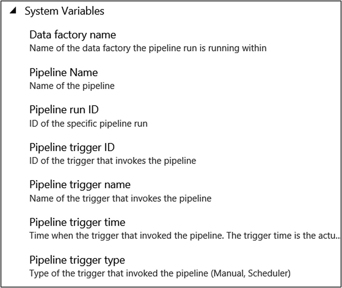
System variables
Functions
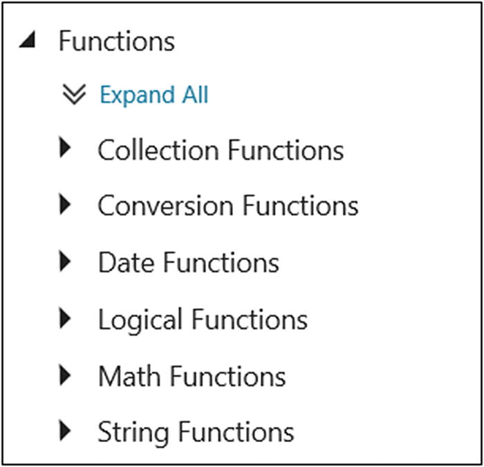
Functions
Activities
In all programing languages there are ways to control the code flow such as for loops, if and until statements, and so on. These all help to decide which part of the code needs to be executed. In Azure Data Factory, the control flow activities help to set the direction of the data pipeline execution. For example, the if condition activity provides a way to decide which activity needs to be executed based on a condition.
Let’s Build the Flow
Let’s build a solution for AdventureWorks to understand how to use the features discussed.
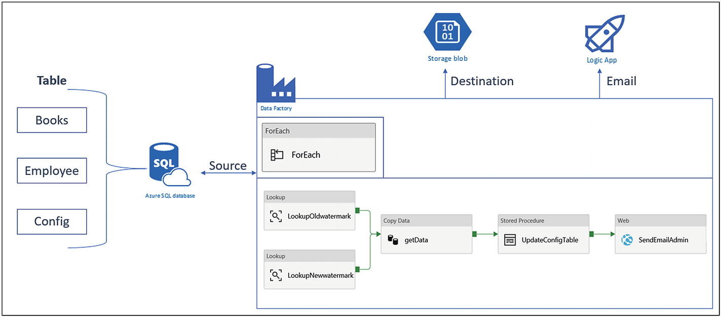
Azure Data Factory pipeline design for delta data loading
Let’s start building this architecture.
Build the Source Database
- 1)
Go to https://portal.azure.com .
- 2)
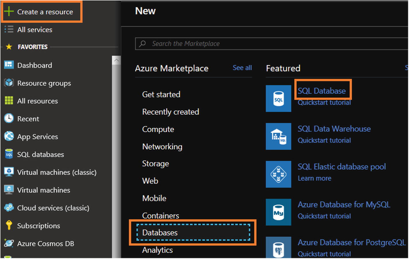
Click “Create a resource.”
- 3)
Click Databases.
- 4)
- 5)
Use ADFControlFlow for “Database name.”
- 6)
Select the subscription where you want to deploy Azure SQL Server.
- 7)
Create or select a resource group.
- 8)
Select “Blank database” for “Select source.”
- 9)
For Server, either create a new server or select an existing server.
- 10)
Select “Not now” for “Want to use SQL elastic pool.”
- 11)
Select the needed pricing tier.
- 12)
Select the default or provide a Collation value.
- 13)
- 14)Once Azure SQL Server is set up, click “Query editor (preview),” as shown in Figure 6-6, or if you are familiar with SQL Server Management Studio, then execute all scripts there.
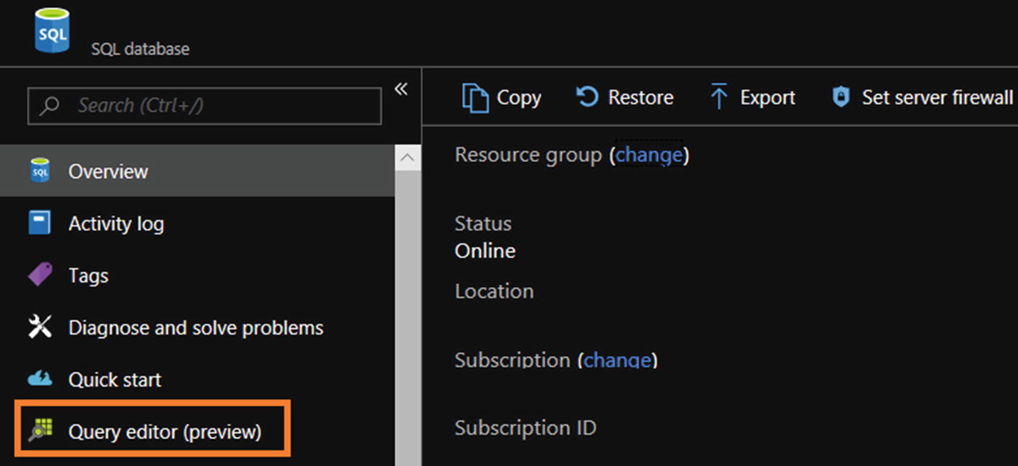 Figure 6-6
SQL query editor
- 15)
Click Login.
- 16)
Select “SQL server authentication” for “Authorization type.”
- 17)
Provide a login and a password.
- 18)Click OK (see Figure 6-7).
 Figure 6-7
SQL query editor login screen
- 19)

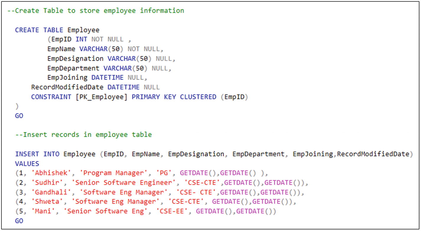
SQL script for table creation and data insertion
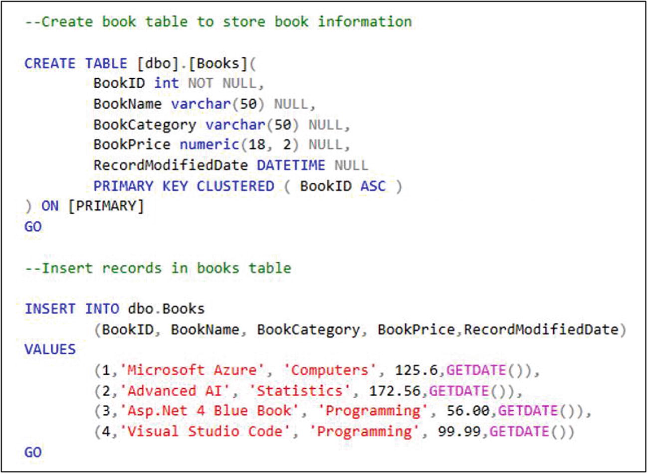
SQL script for table creation and data insertion, continued
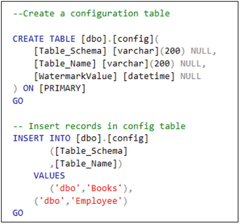
SQL script for table creation and data insertion, continued
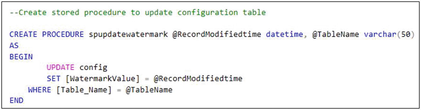
SQL script for stored procedure creation
Build Azure Blob Storage as the Destination
- 1)
Switch to https://portal.azure.com .
- 2)
Click “Create a resource.”
- 3)
Click Storage.
- 4)Click “Storage account - blob, file, table, queue” (see Figure 6-12).
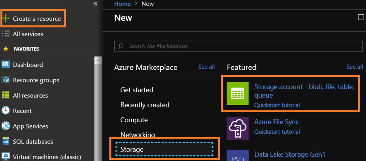 Figure 6-12
Azure Blob Storage service selection
- 5)Provide all the requested information to set up Azure Blob Storage and click Create (see Figure 6-13).
 Figure 6-13
Azure Blob Storage selection
- 6)
Once the Azure Blob Storage setup is done, click “Storage Explorer (preview).”
- 7)Right-click Blob Containers and click Create Blob Container (see Figure 6-14).
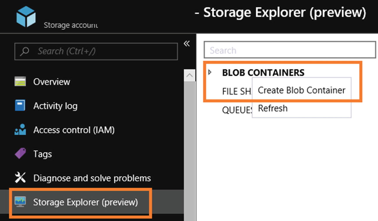 Figure 6-14
Access Azure Storage Explorer (preview)
- 8)Provide a name and public access level (see Figure 6-15).
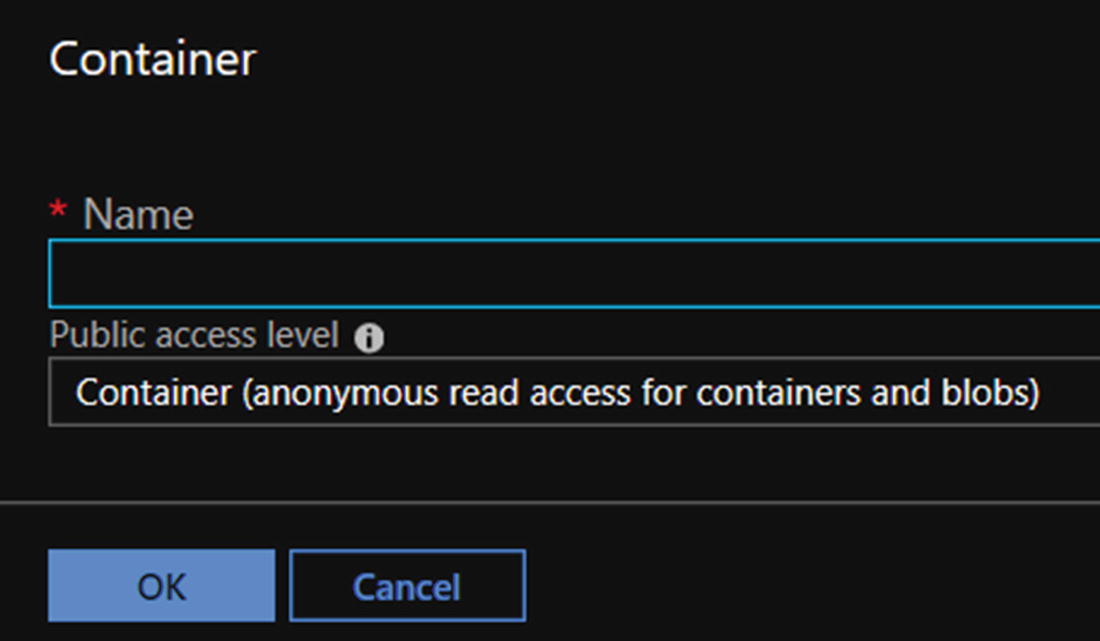 Figure 6-15
Container name and access level screen
- 9)
Click OK.
Build the Azure Logic App
- 1)
Switch to https://portal.azure.com .
- 2)Click “Create a resource,” then Integration, and then Logic App (see Figure 6-16).
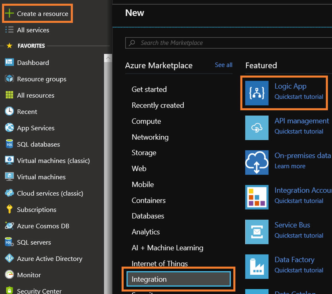 Figure 6-16
Azure Logic App service selection
- 3)Provide a name, select your subscription, create or select a resource group, select the right location, enable or disable Log Analytics, and click Create (see Figure 6-17).
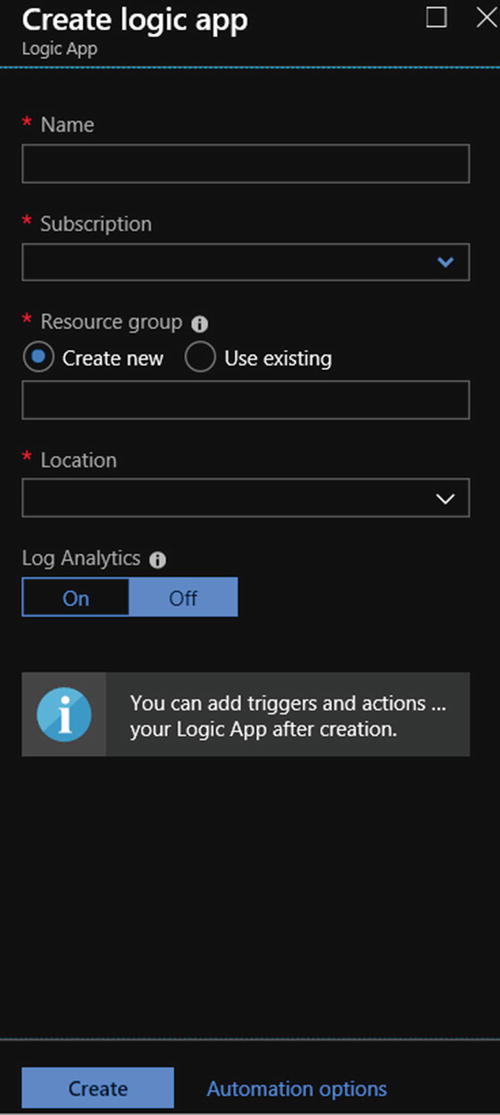 Figure 6-17
Azure Logic App service creation
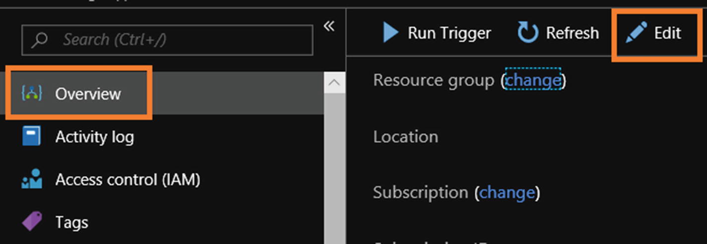
- 4)
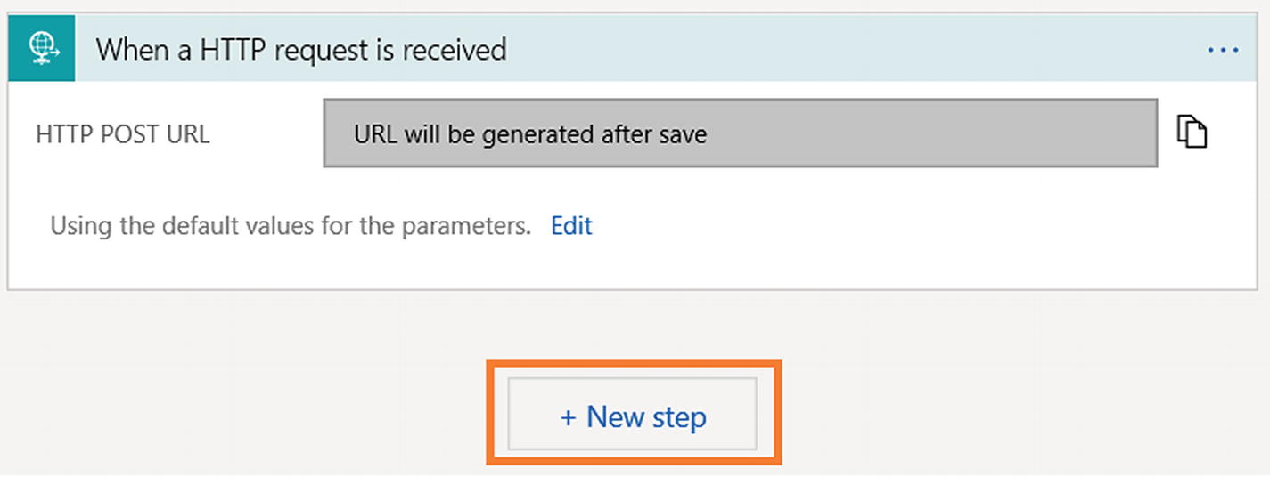
- 5)Select “When a HTTP request is received” from the Logic Apps Designer (see Figure 6-19).
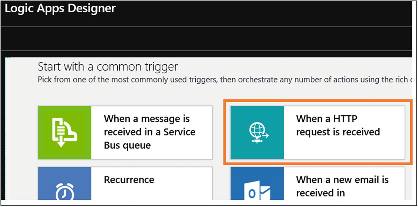 Figure 6-19
Azure Logic App trigger selection
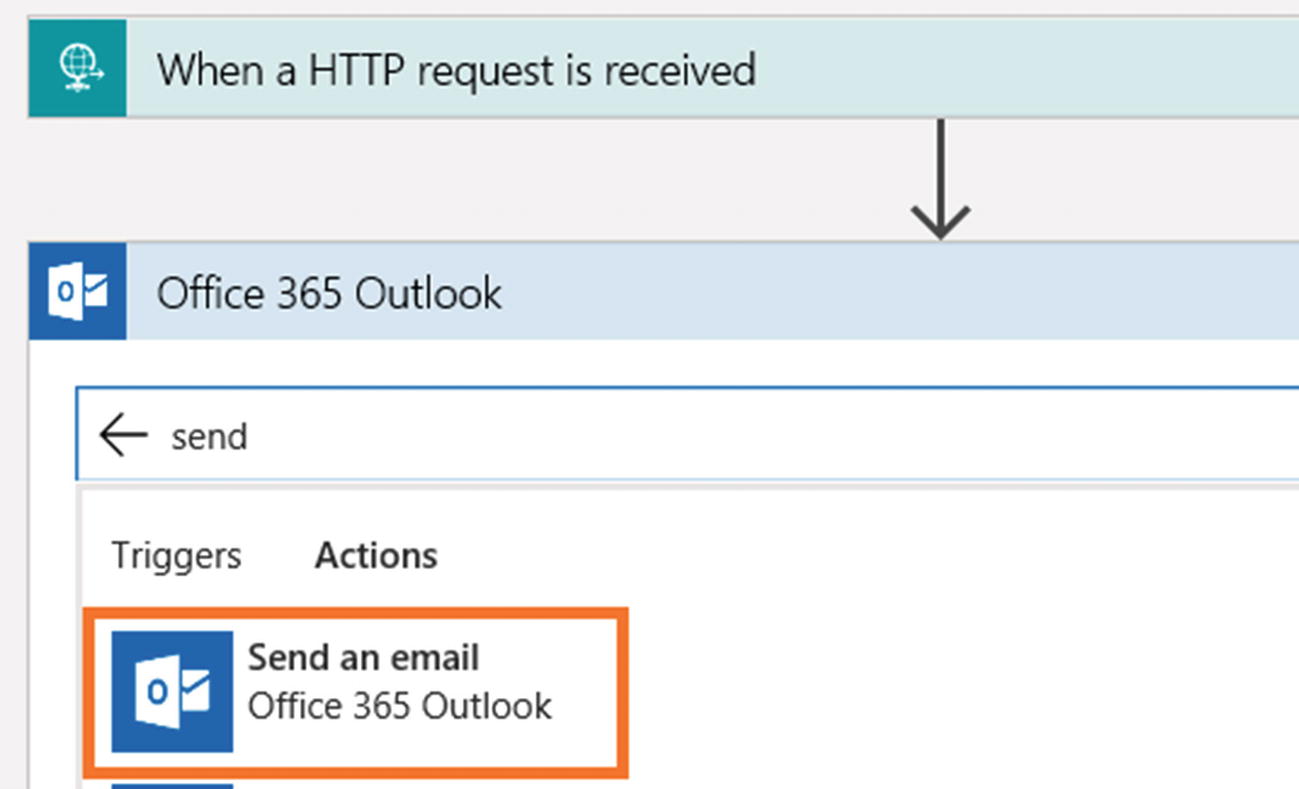
- 6)
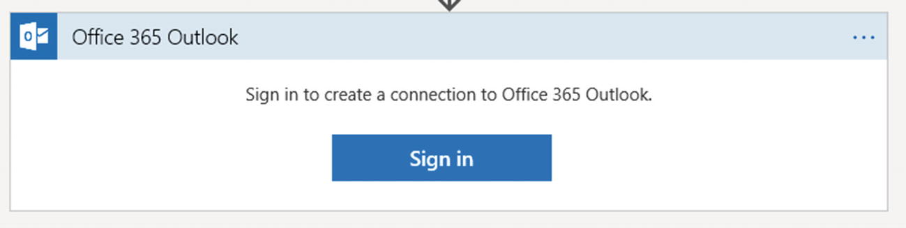
- 7)Click Office 365 Outlook. If you want to use another e-mail provider like Gmail, you can (see Figure 6-21).
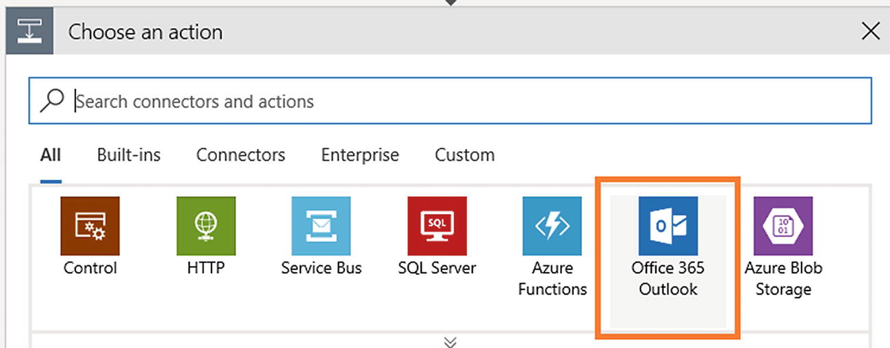 Figure 6-21
Azure Logic App action selection
- 8)
- 9)
- 10)Configure the e-mail settings and click Save (see Figure 6-24).
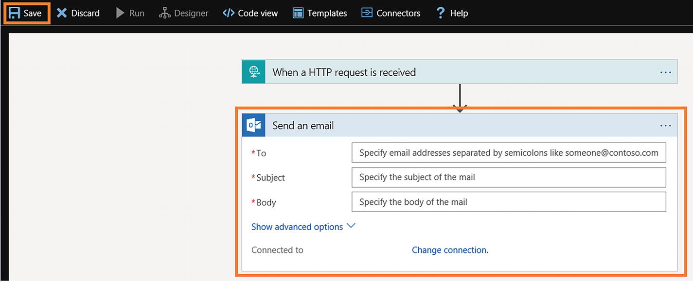 Figure 6-24
Azure Logic App Office 365 Outlook e-mail configuration
- 11)Once the Logic App is saved, you can view the HTTP POST URL (see Figure 6-25).
 Figure 6-25
Azure Logic App HTTP POST URL
- 12)
- 13)The screen will look like Figure 6-27 after entering the value.
 Figure 6-27
Azure Logic App HTTP request body configuration
- 14)In the “Send an email” activity, add a custom message adding dynamic content, as shown in Figure 6-28.
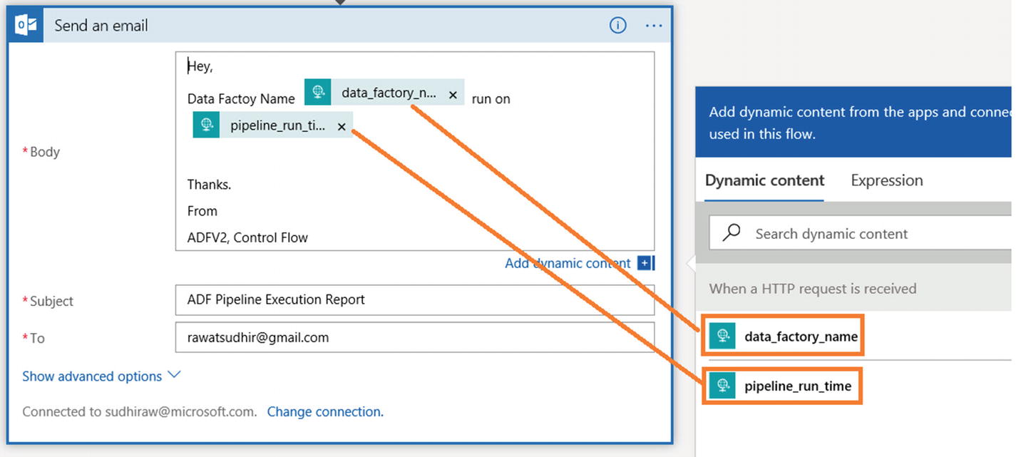 Figure 6-28
Azure Logic App adding dynamic content

Build the Azure Data Factory Pipeline
- 1)
From the Azure portal, click Azure Data Factory services, and click Author & Monitor. If you haven’t set up Azure Data Factory yet, then please refer to the previous chapters to set up the ADF service.
- 2)In the Author & Monitor UI, click Connection and + New (see Figure 6-29).
 Figure 6-29
Azure Data Factory new connection
- 3)Create two connections: one for Azure SQL Database (the service created earlier) and another for Azure Blob Storage (the service created earlier). Please refer to Chapter 5 if you are not sure how to create connections. Once you have created the connections, the screen will look like Figure 6-30.
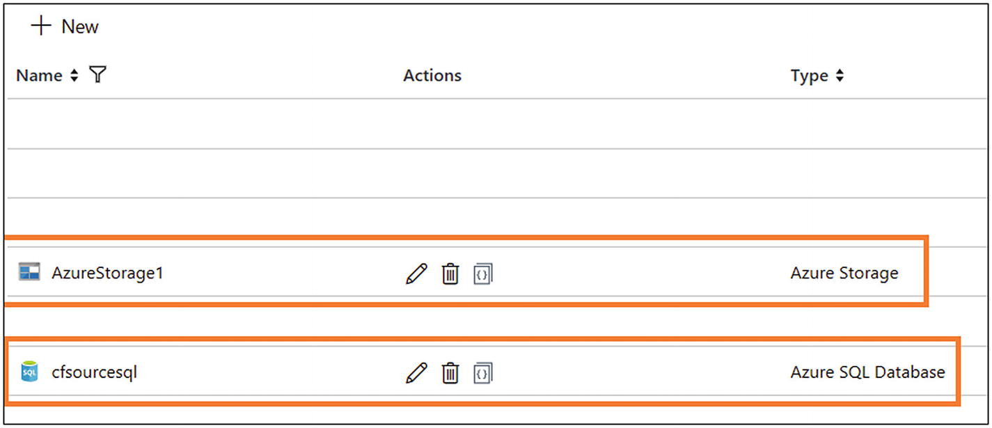 Figure 6-30
Azure Data Factory connections
- 4)Let’s create datasets. Click + and then Dataset (see Figure 6-31).
 Figure 6-31
Azure Data Factory dataset option
- 5)Select Azure SQL Database and click Finish (see Figure 6-32).
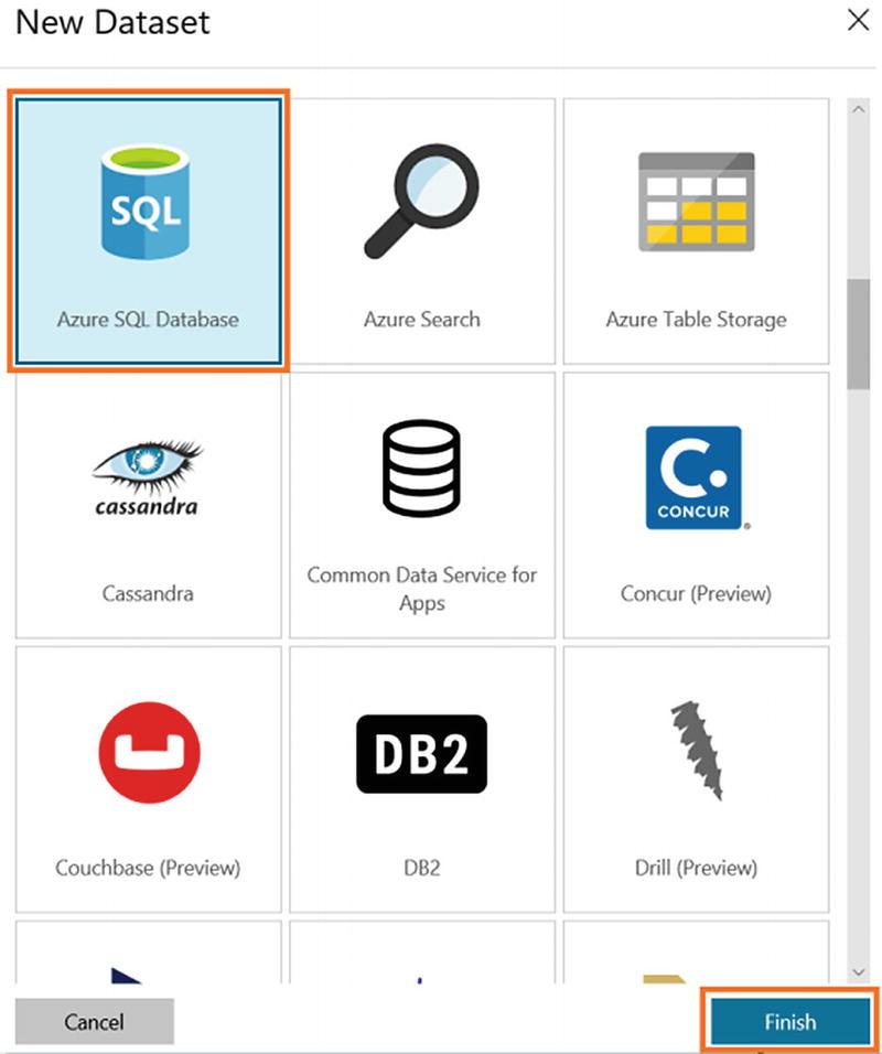 Figure 6-32
Azure Data Factory Azure SQL Database selection
- 6)
On the General tab, provide a name and add a description.
- 7)On the Connection tab, select the connection you created earlier for “Linked service.” Don’t choose any value for Table (see Figure 6-33).
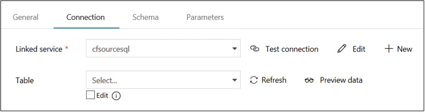 Figure 6-33
Azure Data Factory Azure SQL database configuration
- 8)Let’s create a dataset for Azure Blob Storage. Click + and then Dataset (see Figure 6-34).
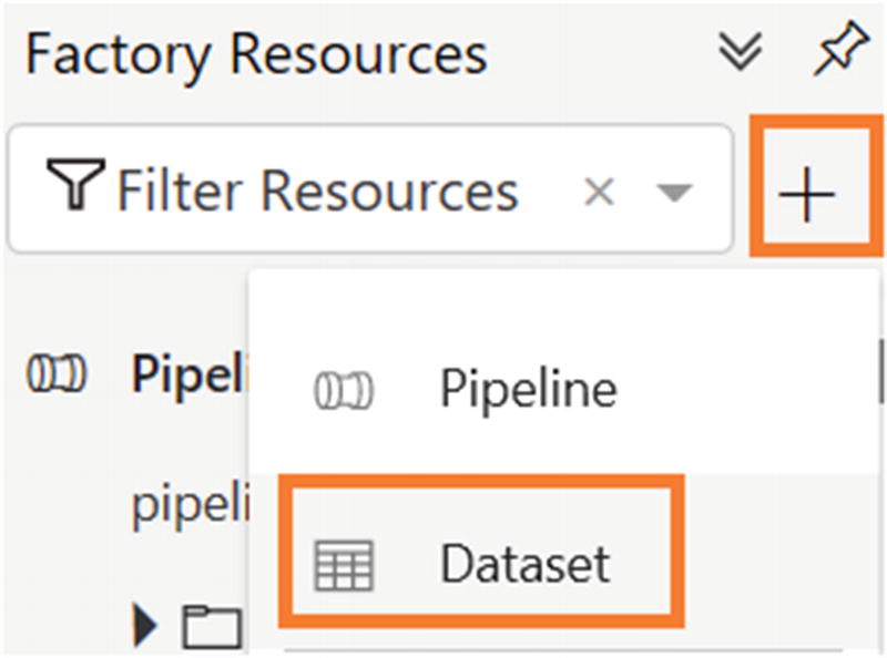 Figure 6-34
Azure Data Factory Dataset option
- 9)Select Azure Blob Storage and click Finish (see Figure 6-35).
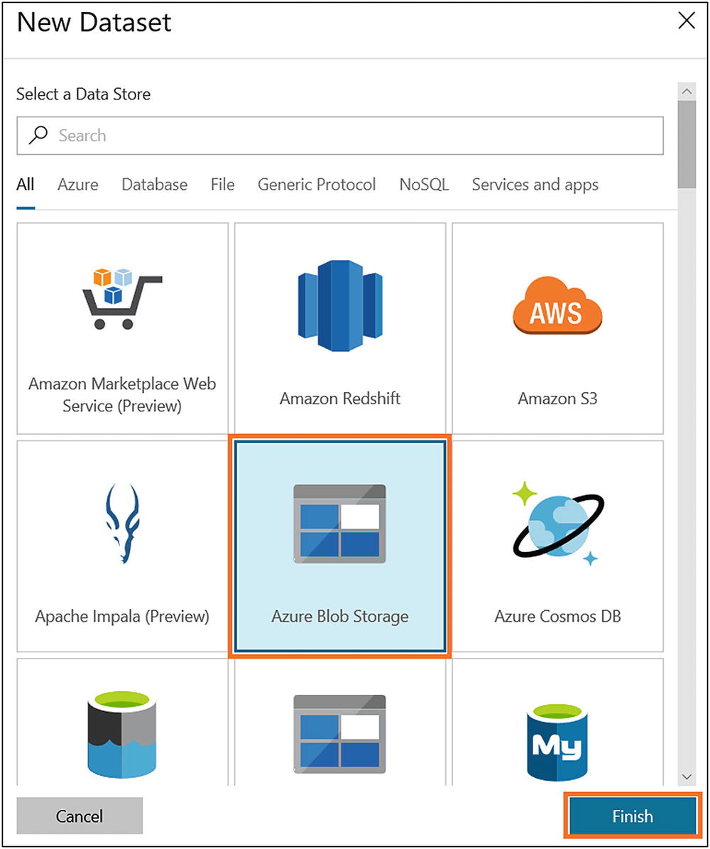 Figure 6-35
Azure Data Factory Azure Blob Storage dataset selection
- 10)
On the General tab, provide a name and add a description.
- 11)On the Parameters tab, click New and provide a variable name for Name, select String for Type, and leave Default Value blank (see Figure 6-36).
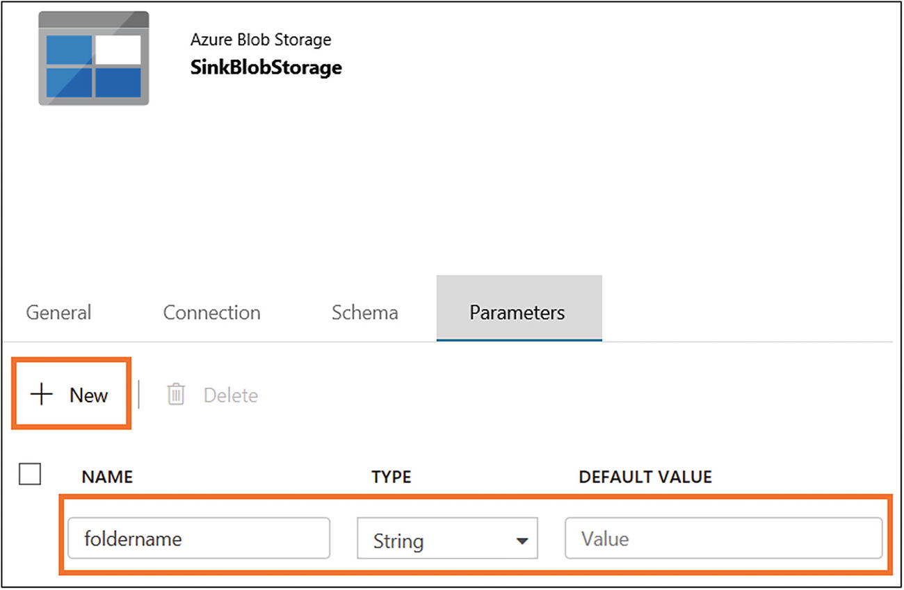 Figure 6-36
Azure Data Factory dataset configuration
- 12)
On the Connection tab, select the linked service you created earlier.
- 13)
Provide a container in “File path” and click the file name area to add the parameter.
- 14)Select the parameter name and click Finish (see Figure 6-37).
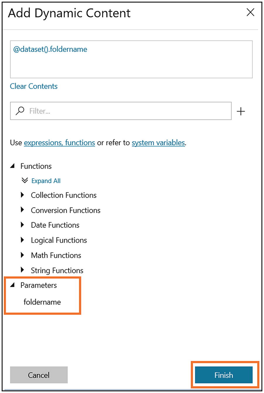 Figure 6-37
Azure Data Factory parameter listing
- 15)Select “Text format” for “File format.” The screen will look like Figure 6-38.
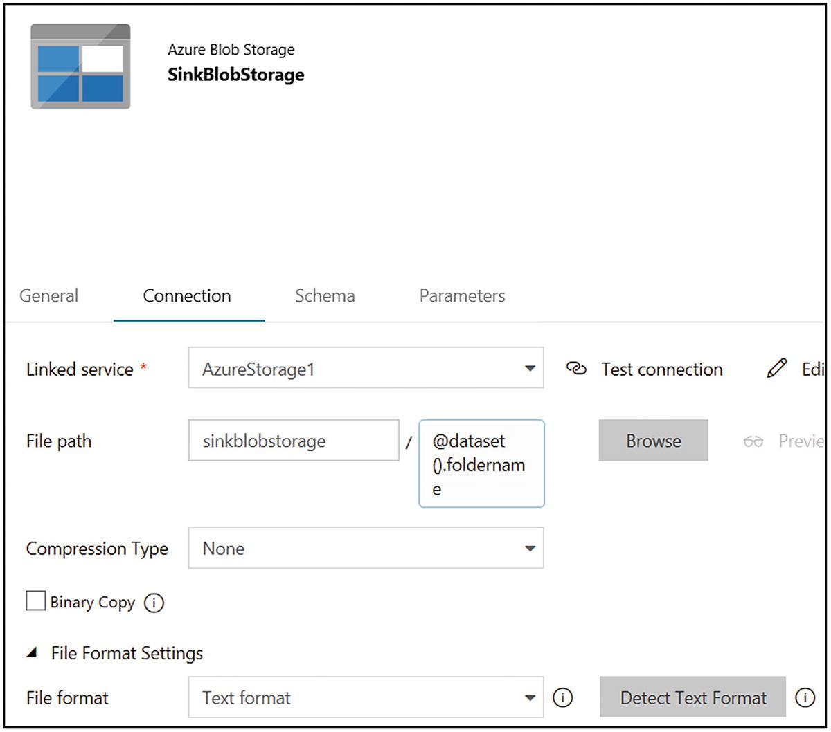 Figure 6-38
Azure Data Factory dataset configuration
- 16)Let’s create a dataset for the config table in Azure SQL. Click + and then Dataset (see Figure 6-39).
 Figure 6-39
Azure Data Factory Dataset option
- 17)
On the General tab, provide a name and add a description.
- 18)On the Connection tab, select the Azure SQL connection created earlier. Provide [dbo].[config] for Table (see Figure 6-40).
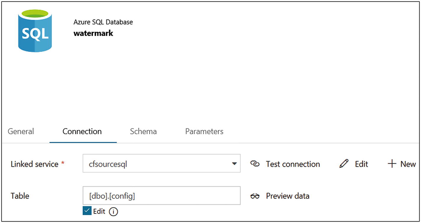 Figure 6-40
Azure Data Factory dataset configuration
- 19)
Once the dataset is set up, let’s create a pipeline. Click + and then Pipeline.
- 20)
On the General tab, provide a name and add a description.
- 21)On the Parameters tab, click + New and create a new parameter, as shown in Figure 6-41.
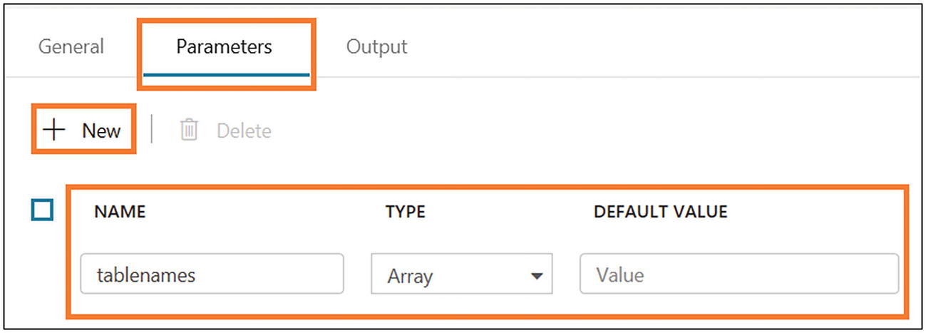 Figure 6-41
Azure Data Factory parameter setting
- 22)Drag and drop a ForEach activity (in Iteration & Conditionals), as shown in Figure 6-42.
 Figure 6-42
Adding a ForEach activity
- 23)
On the General tab, provide a name and add a description.
- 24)In Settings, provide “@pipeline().parameters.tablenames” for Items (see Figure 6-43).
 Figure 6-43
Azure Data Factory configuring activity
- 25)
Under Activities (0), click “Add activity.”
- 26)
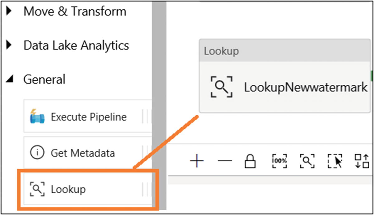
- 27)
On the General tab, provide a name (LookupNewwatermark) and add a description.
- 28)In Settings, select “Azure SQL dataset” for Source Dataset, and select Query for Use Query. Provide the following code in the Query area to get a new watermark:select MAX(@{item().WaterMark_Column}) as NewWatermarkvalue from @{item().TABLE_NAME}
- 29)Select “First row only.” The screen will look like Figure 6-45.
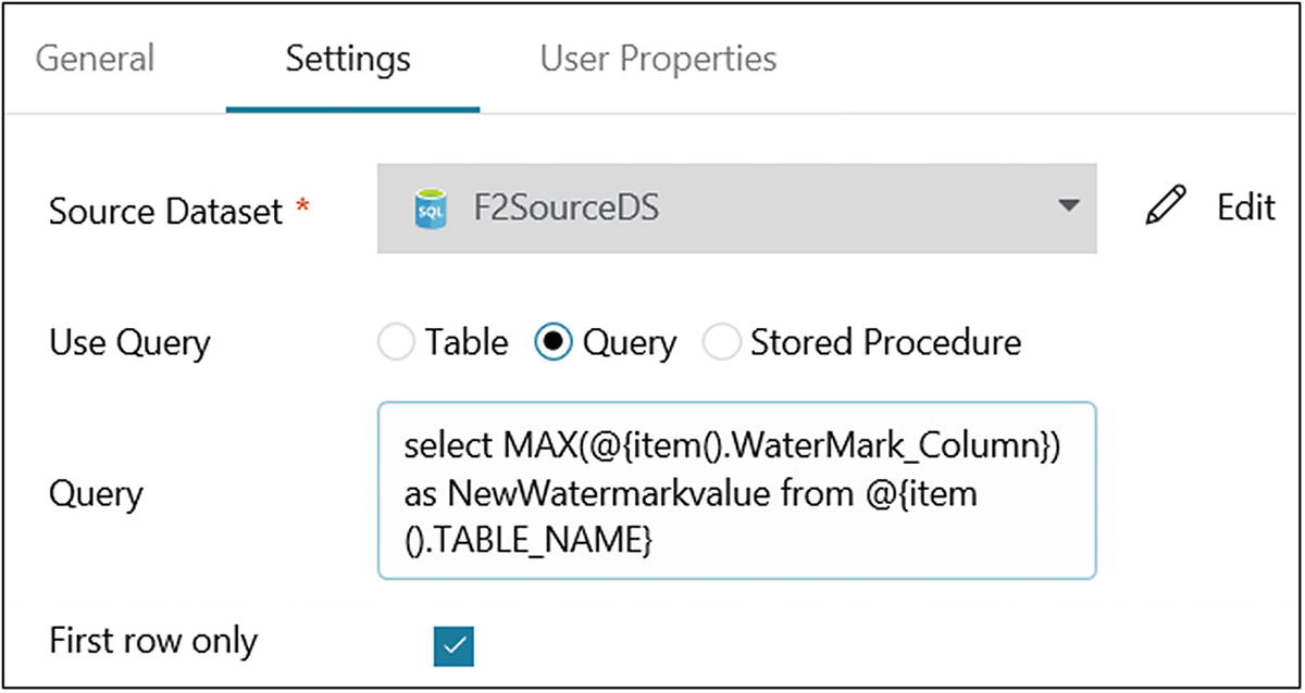 Figure 6-45
Azure Data Factory activity configuration
- 30)
- 31)
On the General tab, provide a name (LookupOldwatermark) and add a description. Let’s use the default values for the rest of the properties.
- 32)
On the Settings tab, select the “watermark” dataset for Source Dataset.
- 33)
Select Query for Use Query.
- 34)Provide the following query in the Query area:select Table_Name, WatermarkValue from Config where Table_Name = '@{item().TABLE_NAME}'
- 35)Select “First row only.” The screen will look like Figure 6-47.
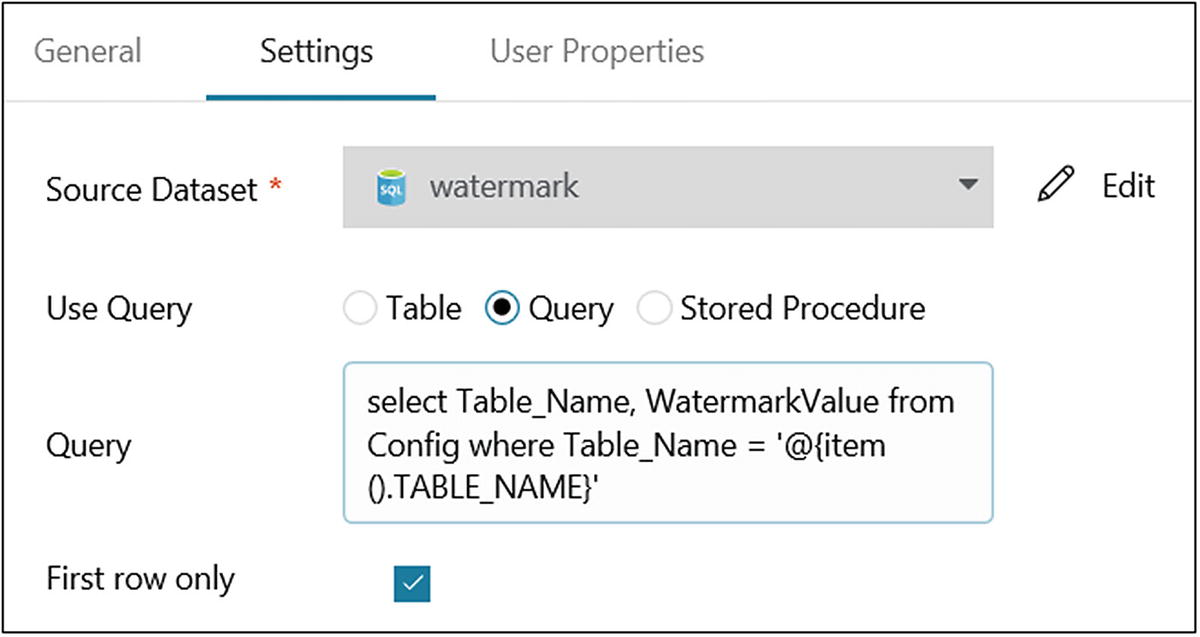 Figure 6-47
Azure Data Factory activity configuration
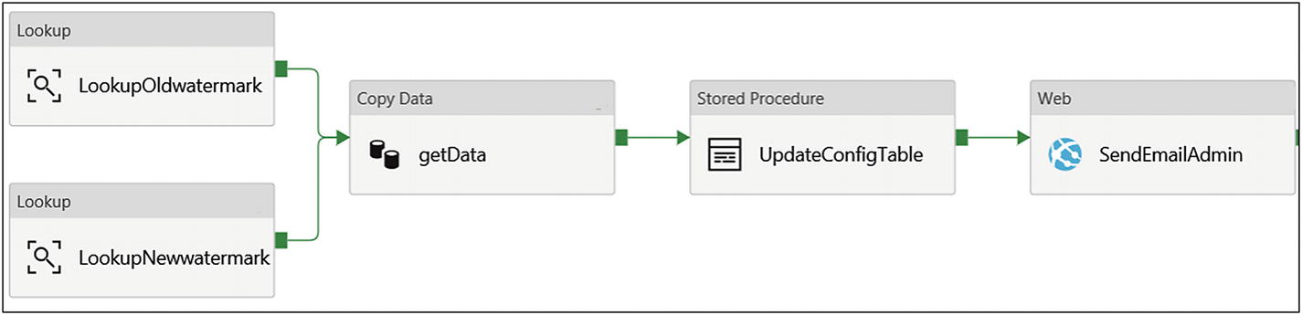
- 36)Drag and drop the Copy Data activity (in Move & Transform). Connect both previous activities to the Copy Data activity (see Figure 6-48).
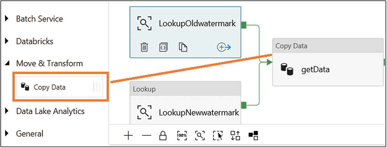 Figure 6-48
Adding a Copy Data activity
- 37)
On the General tab, provide a name (getData) and add a description. Let’s use the default values for the rest of the properties.
- 38)
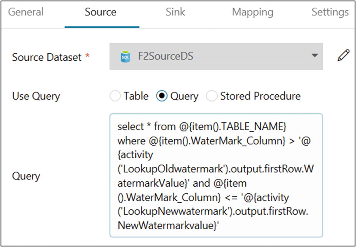
On the Source tab, select “Azure SQL dataset” for Source Dataset. Select Query for Use Query.
- 39)Provide the following query for Query:select * from @{item().TABLE_NAME} where @{item().WaterMark_Column} > '@{activity('LookupOldwatermark').output.firstRow.WatermarkValue}' and @{item().WaterMark_Column} <= '@{activity('LookupNewwatermark').output.firstRow.NewWatermarkvalue}'

- 40)
On the Sink tab, select Azure Blob Storage for Sink Dataset.
- 41)Provide the following for the folder name:@CONCAT(item().TABLE_NAME, pipeline().RunId, '.txt')
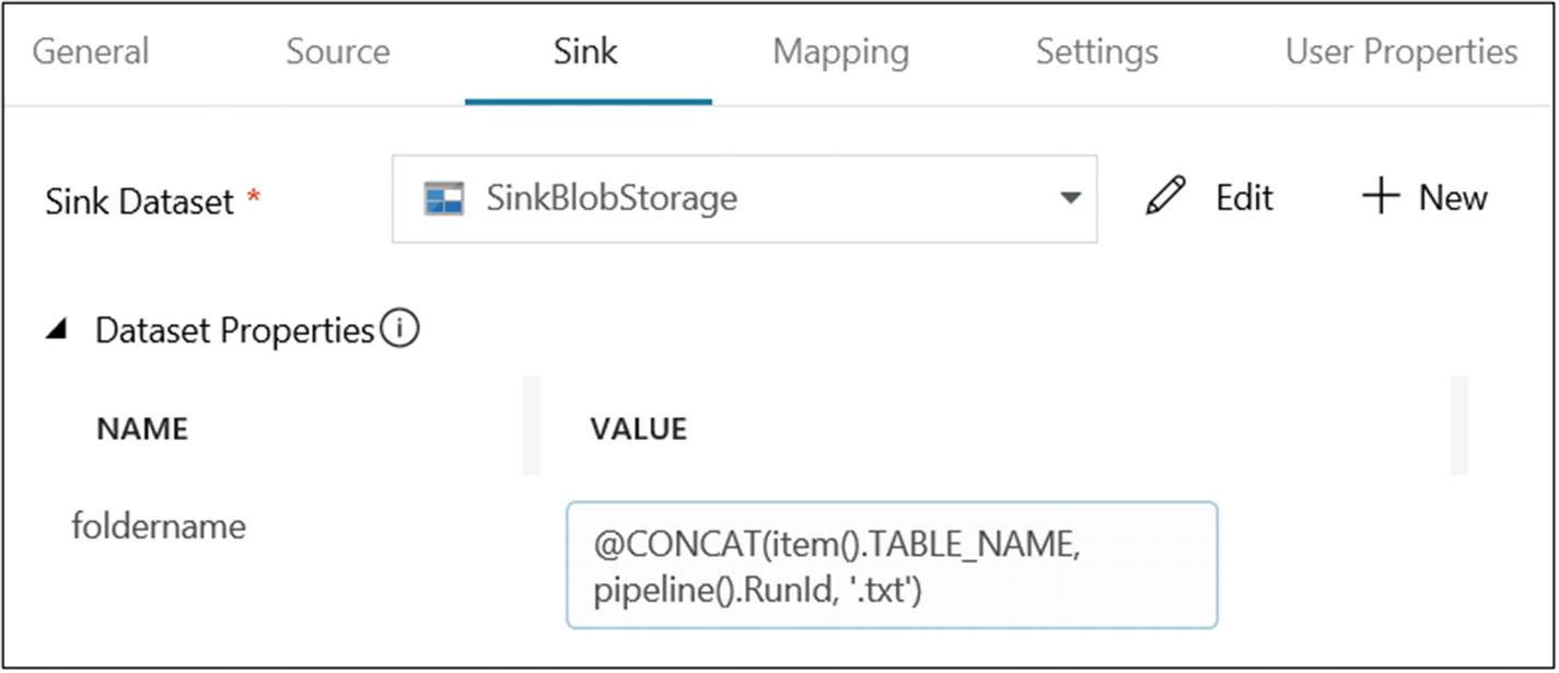
Copy Data activity sink configuration
- 42)Drag and drop the Stored Procedure activity and connect it from the Copy Data (getData) activity (see Figure 6-51).
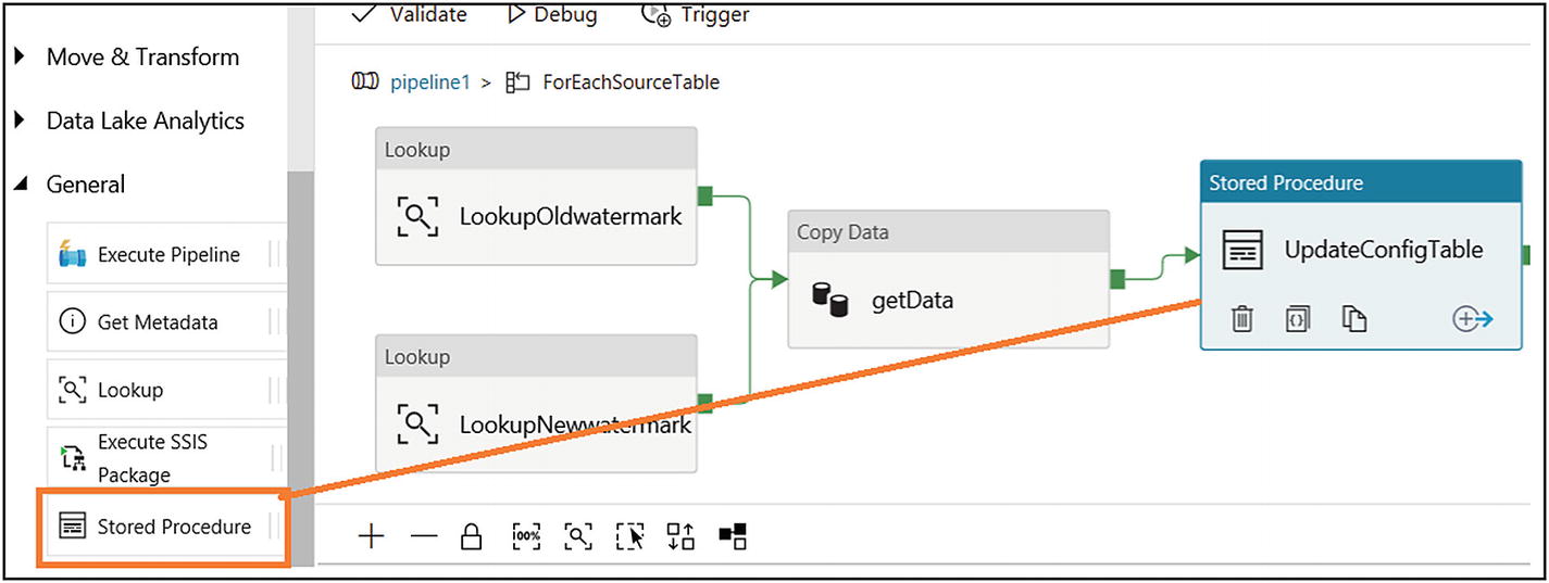 Figure 6-51
Stored Procedure activity
- 43)
On the General tab, provide a name (UpdateConfigTable) and add a description. Let’s use the default values for rest of the properties.
- 44)Under SQL Account, select “Azure SQL connection” for “Linked service” (see Figure 6-52).
 Figure 6-52
Stored Procedure activity configuration
- 45)
Provide “[dbo].[spupdatewatermark]” for “Stored procedure name.”
- 46)Click + New for “Stored procedure parameters.” Create the parameters listed in Table 6-1.Table 6-1
Azure Data Factory Parameter Configuration
Name
Type
Value
RecordModifiedtime
DateTime
@{activity(‘LookupNewwatermark’).output.firstRow.NewWatermarkvalue}
TableName
String
@{activity(‘LookupOldwatermark’).output.firstRow.Table_Name}
- 47)After creating the parameters, the screen will look like Figure 6-53.
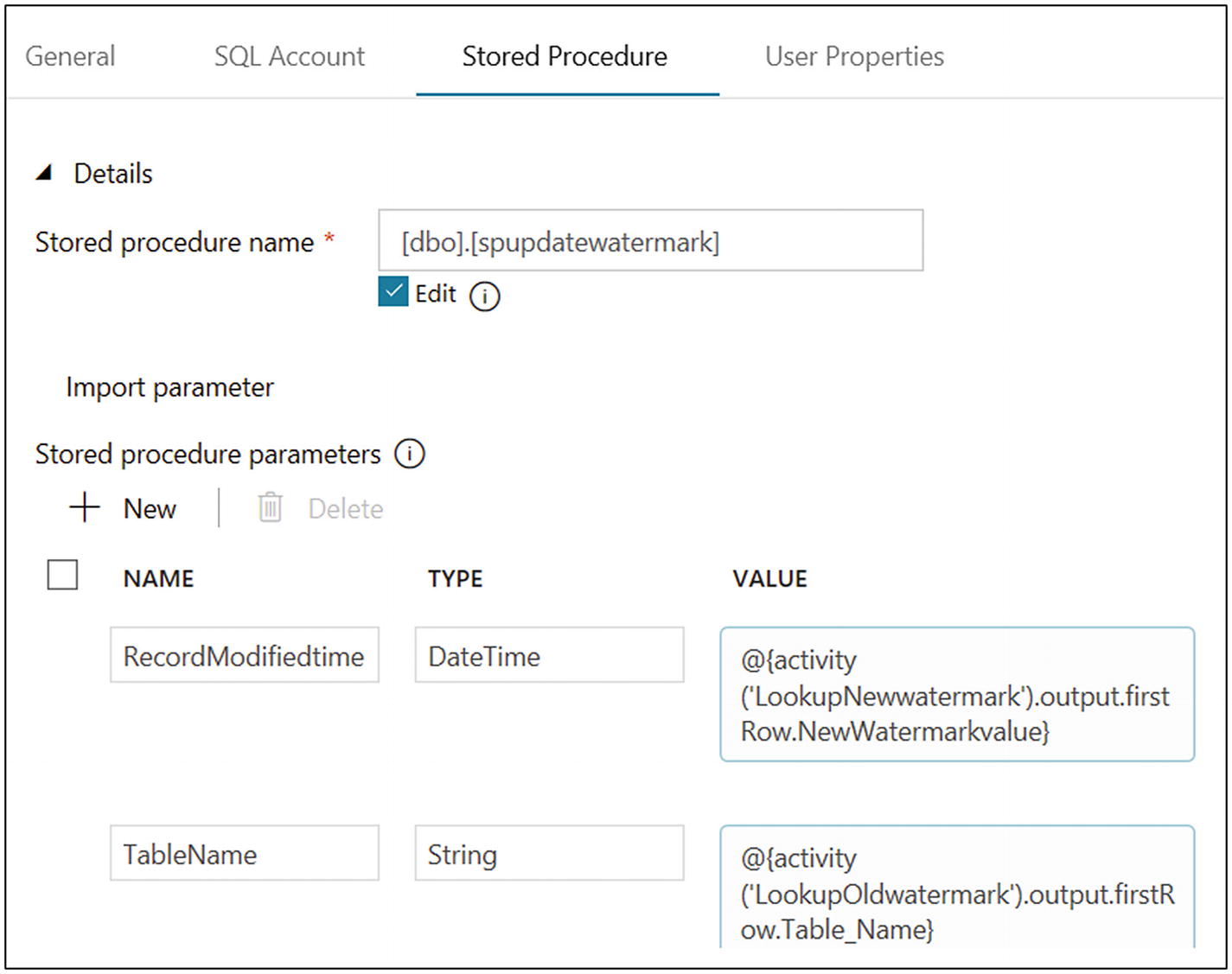 Figure 6-53
Stored Procedure activity parameter configuration
- 48)Drag and drop the Web activity and connect it to the Stored Procedure (UpdateConfigTable) activity (see Figure 6-54).
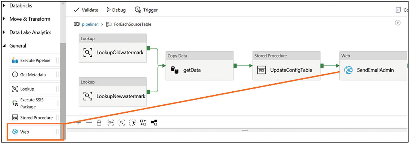 Figure 6-54
Stored Procedure activity parameter
- 49)
On the General tab, provide a name (UpdateConfigTable) and add a description. Let’s use the default values for rest of the properties.
- 50)
On the Settings tab, provide the URL (copied from the Azure logic apps).
- 51)
Select POST for Method.
- 52)Add the following value in Body:{pipeline_run_time: @{pipeline().TriggerTime},data_factory_name:@{pipeline().DataFactory}}

- 53)
- 54)
Click Publish All.
- 55)
Click Trigger and then “Trigger now.”
- 56)Provide the following value for the tablenames parameter:[{"TABLE_NAME": "Employee","WaterMark_Column": "RecordModifiedDate"},{"TABLE_NAME": "Books","WaterMark_Column": "RecordModifiedDate"}]
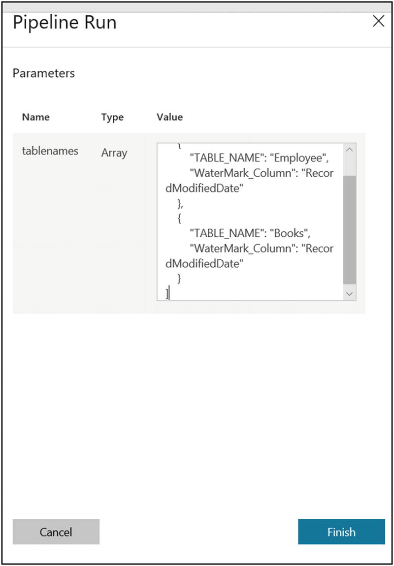
- 57)
Click Finish.
- 58)Click Monitor and click to drill down to see each activity run. All activity except the main activity (ForEachSourceTable) will run twice because you passed two tables to load data (see Figure 6-58).
 Figure 6-58
Azure Data Factory monitoring
- 59)In Azure Blob Storage, you will find two files, as shown in Figure 6-59.
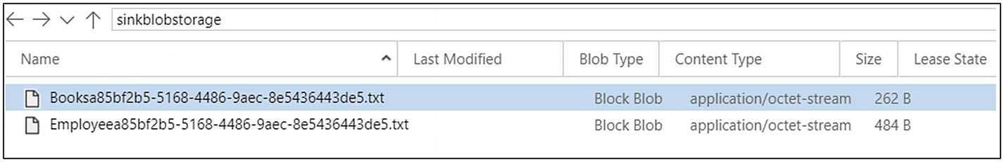 Figure 6-59
Azure Data Factory output
- 60)Open the files to look at the data (see Figure 6-60).
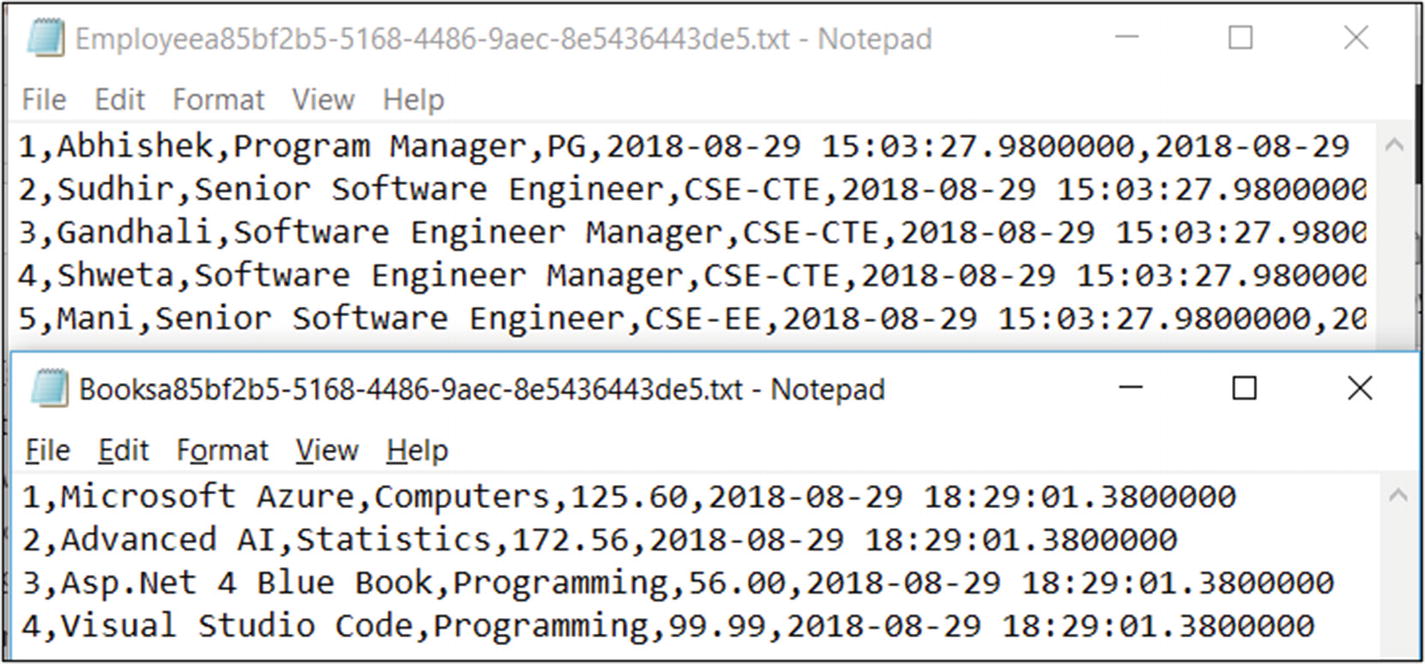 Figure 6-60
Azure Data Factory output
- 61)Check the e-mail account; you should see an e-mail like in Figure 6-61.
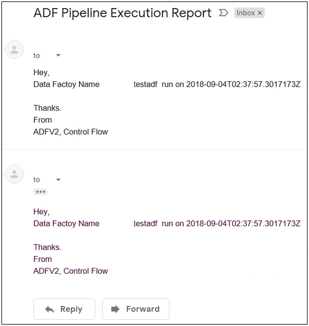 Figure 6-61
Azure Data Factory pipeline execution report e-mail
- 62)In Azure SQL Server, check the WatermarkValue config table (see Figure 6-62).
 Figure 6-62
Watermark value update
- 1)Run the code shown in Figure 6-63 to insert records into an Azure SQL table.
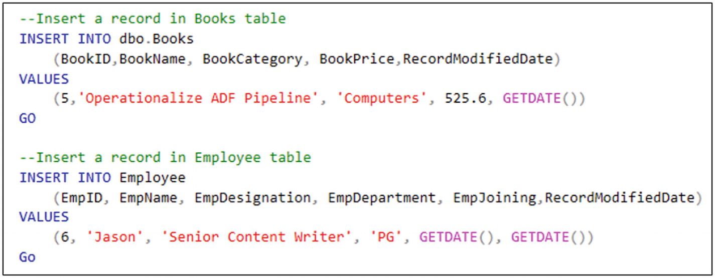 Figure 6-63
SQL script for data insertion
- 2)
Run an Azure Data Factory pipeline.
- 3)Look Azure Blob Storage and you will find two more files (selected in Figure 6-64).
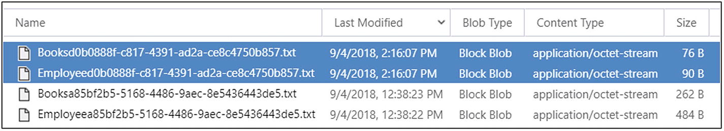 Figure 6-64
Azure Data Factory output
- 4)Open the files to see the new data (see Figure 6-65).
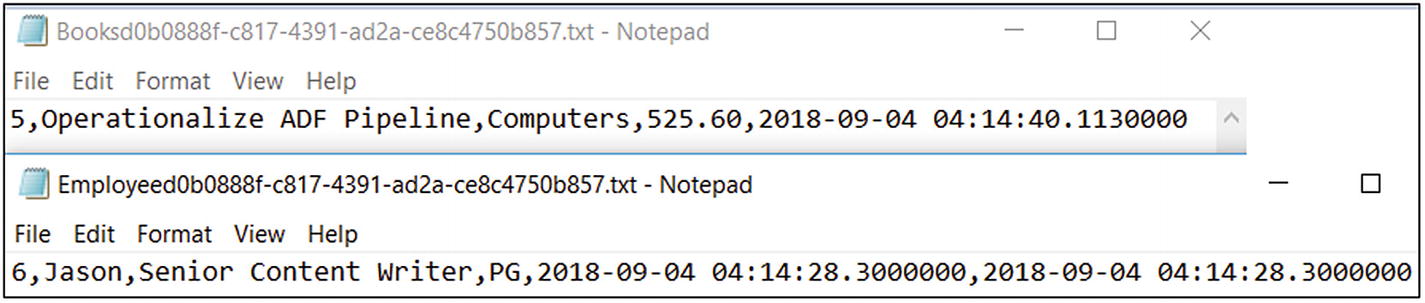 Figure 6-65
Azure Data Factory output data
- 5)

You built a solution to understand how the flow can be handled within Azure Data Factory. There are other functions and activities that can be used on a case-by-case basis.
Summary
In this chapter, you learned about managing the data pipeline flow and learned how to use expressions, functions, and activities to control the data flow in Azure Data Factory.