
Hour 18. Animators
What You’ll Learn in This Hour:
• The basics of animators
• How to create the animators
• How to manage an animator with scripts
This hour you will be taking what you learned about animations previously and putting it to use with Unity’s new Mecanim animation system and animators. You will start by learning about animators and how they work. From there you will look at how to rig, or change the rigging, of models in Unity. After that you will create an animator and configure it. You will finish the hour by manipulating your animator through scripts to build an interactive demo.
Note: Try It Yourself
Due to the complexity of animators, this hour will function like a big “Try-It-Yourself”. This means that you should be following along and completing all of the steps in the text as they are covered. By doing so, you are sure to have a project ready to go when things start coming together. There are several hours in this book where you can idly read along. This isn’t one of them!
Animator Basics
Last hour you learned to manually control individual animations. Using that system, you are capable of performing advanced processes like transitions and blending. Doing so, however, is cumbersome and tedious. This hour you will get to work with Unity’s new animation system which is called Mecanim. This system utilizes an asset called an animator which has several animations and transitions applied to it. The animator is then applied to a model to make it move. The nice thing about this system is that you can create a single animator and apply it to several different models and have them all animate in a similar fashion. Before you can build an animator though, you will need to ensure that your models are properly rigged and your animations are properly set up.
Rigging Models
If you recall from the previous hour, models and animations have to be rigged exactly the same way in order to function. This means that getting animations made for one model to work on a different model is very difficult. With the new Mecanim system, models can have their rigging remapped in the editor without using any 3D modeling tools. The result is that any animation made for a Mecanim model can work with any model that has its rigging remapped in Unity. Now animators can produce large libraries of animations that can be applied to a large range of models using many different rigs!
The rigging for models is completed in the inspector view. For this section you will be using a model called “Jack” which was made by the talented Matt Muzzy (http://www.mattmuzzy.com/). You can find this model in the folder named “Jack” which is located in the book assets for Hour 18. The “Jack” model comes with a rigging already, and it will need to be configured in Unity to work with an animator. To import and configure the model:
1. Create a folder named “Models” and drag the “Jack” folder from the book assets into it.
2. In Unity, look in the “Jack” folder for the model named “Jack1”. Select this model. In the inspector, click the “Animations” tab and unselect the “Import Animation” property. Click “Apply”.
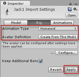
3. In the “Rig” tab, change the “Animation Type” to “Humanoid”. This will cause the “Avatar Definition” property to appear. This is where the rig mapping is done. Look at Figure 18.1 to ensure your properties match and then click “Apply”.
Figure 18.1. The “Rig” settings
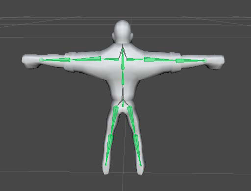
4. Click the “Configure” button to open of the rig editor. If you are prompted to save the scene go ahead and do so. In the rig editor, you will see the model standing in what is called the “T-Pose” (see Figure 18.2).
Figure 18.2. Jack in a “T-Pose”.
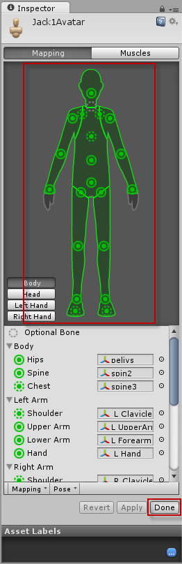
5. Ensure that all of the joints are green (see Figure 18.3) and click “Done”.
Figure 18.3. A successful rigged model.
The model “Jack” is now ready to go.
Red Rig of Death
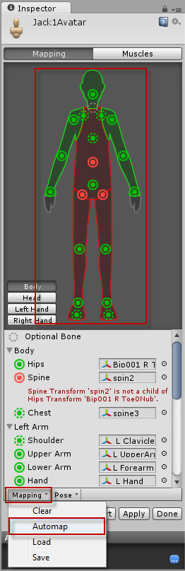
Hopefully the above steps worked exactly as planned and everything appeared green right away. That is not always the case though. Sometimes, Unity needs some assistance with guessing how a model is rigged. Figure 18.4 illustrates a model that was incorrectly rigged. In this instance, the spine joint was incorrectly matched. To fix this, you would need to click “Mapping->Automap”. Doing so will cause Unity to correctly analyze the model and fix the issue. If automapping isn’t working for your particular model, you may need to find and map the joints manually.
Figure 18.4. An incorrectly mapped model.
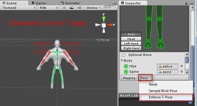
Sometimes, the model’s rig will be mapped correctly, but some of the joints are appearing red (see Figure 18.5). This is the result of pose restrictions and can be solved by clicking “Pose->Enforce T-Pose”.
Figure 18.5. Enforcing a T-Pose.
These simple methods will fix most if not all of your model rigging issues.
Animation Preparation
For this hour you will be using a set of Mecanim animations. These animations were provided by Unity in their Mecanim demo. For the sake of time savings, however, you can find the animation files in the folder named “Animations” located in the book assets for Hour 18. If you look in that folder, you will notice that the animations are actually .fbx files. This is because the animations themselves are located inside their default models. Don’t worry though, we will be able to modify and extract them inside Unity.
Each animation will need to be specifically configured the way you want it. For example, you will need to ensure that the walking animation loops appropriately so that transitions don’t have any obvious seems. In this section, you are going to go through each animation and prepare it. Start by dragging the “Animations” folder from the book assets into the Unity editor. There are three animations that you will be working with: “Idles”, “WalkForward”, and “WalkForwardTurns”. Also, each of these three animations will need to be set up uniquely.
Idle Animation
To set up the idle animation, you will need to do the following:
1. Select the “Idles.fbx” file in the “Animations” folder. In the inspector, select the “Rig” tab. Change the “Animation Type” to “Humanoid” and configure the rig exactly as you did for the “Jack” model above. You may need to go back and reference that section and repeat the steps.
2. Once the rig is configured, click the “Animations” tab in the inspector. The only thing you will need to do here is check the “Loop Pose” property. Ensure that your settings match the ones in Figure 18.6.
Figure 18.6. The idle animation properties.
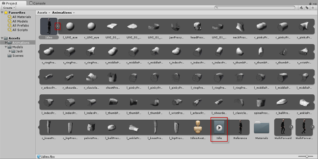
3. The animation itself should now be properly configured. It can be found by expanding the “Idles.fbx” file (see Figure 18.7). Be sure to remember how to access that animation. The model itself is irrelevant. It’s the animation you want.
Figure 18.7. Finding the animation in the model.
Note: Red Light Green Light
You may have noticed the green circles present in the animation settings (see in Figure 18.6 above). Those are nifty little tools that are used to designate whether or not your animations are lined up. The fact that the circles are green means that they will loop seamlessly. If any circles had been yellow, it would indicate that the animation came close to looming seamlessly but there was a minor difference. A red circle indicates that the beginning and end of the animation don’t line up at all and a seam would be very apparent. If you have an animation that doesn’t line up, you can change the “Start” and “End” properties to find a segment of the animation that does.
Walk Animation
To set up the walking animation, you will do the following:
1. Select the “WalkForward.fbx” file in the “Animations” folder and complete the rigging the same way you did for the idle animation.
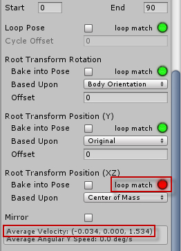
2. Under the “Animations” tab, you should have the settings demonstrated in Figure 18.8. You should note two things. First, the “Root Transform Position (XZ)” has a red circle next to it. This is good. What this means is that at the end of the animation the model is in a different x and z axis position. Since this is a walking animation, that is the behavior that you want. The other thing you should notice is the “Average Velocity” indicator. You should notice an x axis velocity of -0.034 and a z axis velocity of 1.534. The z axis velocity is good because you want to model moving “forward” but the x axis velocity is a problem as it will cause the model to drift sideways while walking. It will need to be adjusted.
Figure 18.8. The walk animation settings.
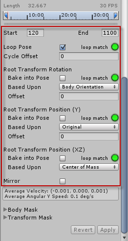
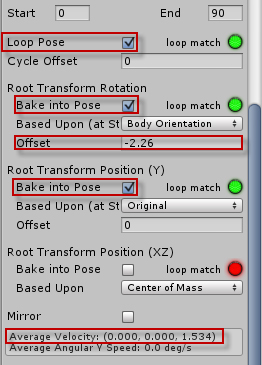
3. To adjust the x axis velocity, you will need to check the “Back into Pose” properties for both the “Root Transform Position” and “Root Transform Position (Y)” properties. You will also need to set the “Root Transform Position” offset to -2.26. Finally, you will want to check the “Loop Pose” property. Figure 18.9 contains the fixed settings. When done click the “Apply” button.
Figure 18.9. The fixed walk animation settings.
Walk Turn Animation
The walk turn animation allows the model to smoothly change facing while walking forward. This one will be a little different from the other two because you will need to make two animations out of a single animation recording. This sounds trickier than it really is. The steps to complete this are:
1. Select the “WalkForwardTurns.fbx” file in the “Animations” folder and complete the rigging the same way you did for the idle animation.
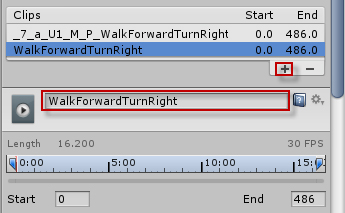
2. By default there will be a long animation with the name “_7_a_U1_M_P_WalkForwardTurnRight”. You could modify that, but it will be easier to just delete it and start over. Type “WalkForwardTurnRight” into the clip name text field and then click the plus sign (+) to create a new clip (see Figure 18.10).
Figure 18.10. Adding an animation clip.
3. Now you can remove the old animation clip. Select “_7_a_U1_M_P_WalkForwardTurnRight”. And click the minus sign (-) to remove it.
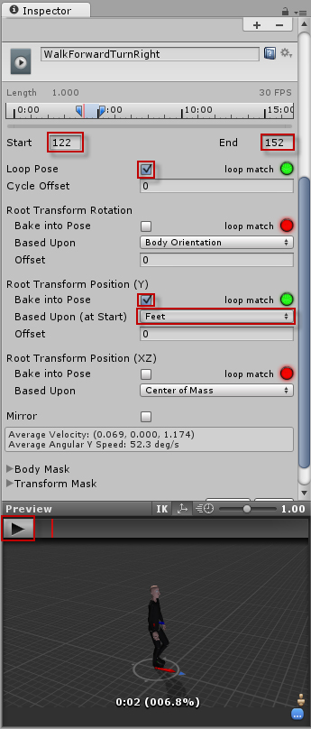
4. With the “WalkForwardTurnRight” clip selected, set the properties to match Figure 18.11. This will cut the clip down and ensure that it only contains the model moving is a rightward circle (be sure to preview it to see what it looks like). Once done, click “Apply”.
Figure 18.11. The “Right Turn” settings.
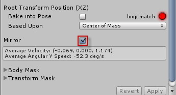
5. Create a “WalkForwardTurnLeft” animation clip the same way you made the right turning clip in step 2 above. The properties for the “WalkForwardTurnLeft” clip will be exactly the same as the “WalkForwardTurnRight” clip except you will need to put a check in the “Mirror” property (see Figure 18.12).
Figure 18.12. Mirroring the animation.
At this point, all of the animations are set up and ready to go. Now all that’s left to do is build the animator.
Creating an Animator
Animators in Unity are assets. This means that they are a part of a project and exist outside of any one scene. This is nice because it allows easy reuse over and over again. To add an animator to your project, in the project view right click a folder and select “Create->Animator Controller”.
In this exercise you will be setting up a scene and preparing for the rest of the materials for the hour. Be sure to save the scene created here as it will be needed later.
1. If you have not done so already, create a new project and complete the model and animation preparation steps in the previous section.
2. Drag the “Jack1” model into your scene and give it a position of (0, 0, -5). Add a directional light to the scene.
3. Select the “Jack1” model in the scene. Locate the “Jack Diffuse1.psd” texture in the “Jack” folder and drag it onto the “Jack1” model in the scene. Nest the main camera under the “Jack1” model and position the camera at (0, 1.5, -1.5) with a rotation of (20, 0, 0).
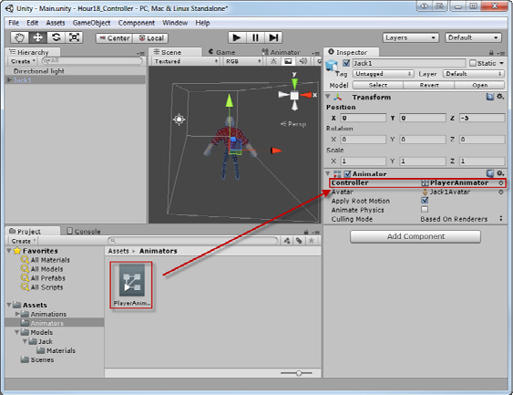
4. Create a new folder named “Animators”. Right click the new folder and select “Create->Animator Controller”. Name the animator “PlayerAnimator”. With “Jack1” selected in the scene, drag the animator onto the “Controller” property of the “Animator” component in the inspector (see Figure 18.13).
Figure 18.13. Adding the animator to the model.
5. Add a plane to your scene. Position the plane at (0, 0, -5) with a scale of (50, 1, 50). Locate the file “Checker.tga” in the book assets for Hour 18 and import it into your project. Apply the texture to the plane.
6. Run the scene and make sure everything looks correct. Note that at this point, nothing is animated.
The Animator View
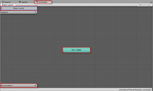
Double clicking on an animator brings up the animator view. This view functions like a flow graph allowing you to visually create animation paths and blending. This is the real power of the Mecanim system. Figure 18.14 shows the basic animator view. For a new animator, this is very plain. There is only a base layer, no parameters, and an “Any State”. These will soon be expanded upon.
Figure 18.14. The animator view.
The Idle Animation
The first animation you will want to apply to Jack is the idle animation. Now that the entire long set up process is complete, adding this animation is simple. You will need to locate the “Idle” animation clip which is stored inside the “Idles.fbx” file (see Figure 18.7 above) and drag it onto the animator in the animator view (see Figure 18.15).
Figure 18.15. Applying the idle animation.
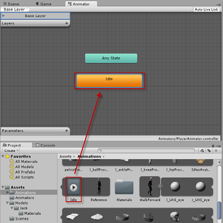
You should now be able to run your scene and see the Jack model looping through the idle animation.
Parameters
Parameters are like variables for the animator. You set them up in the animator view and then manipulate them with scripts. These parameters control when animations are transitioned and blended. To create a parameter, simply click the plus sign (+) in the “Parameters” box in the animator view.
In this exercise you will be adding two parameters. This exercise builds off of the project and scene you have been working on thus far this hour.
1. Make sure you’ve completed all of the steps up to this point.
2. In the animator view, click the plus sign (+) to create a new parameter. Choose a float parameter and name is “Speed” (see Figure 18.16).
Figure 18.16. Adding parameters.
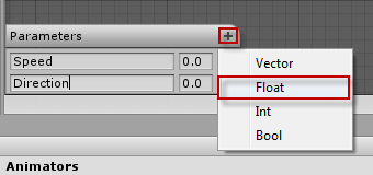
3. Repeat step 2 to create a parameter named “Direction”.
States and Blend Trees
Your next step is to create a new state. States are essentially statuses that the model is currently in that define what animation is playing. The model Jack will have two states: Idle and Walking. Idle is already in place. Since the walking state can be any of three animations, you will want to create a state that uses a blend tree. A blend tree will seamlessly blend one or more animations together based on some parameter. To create a new state, complete the following:
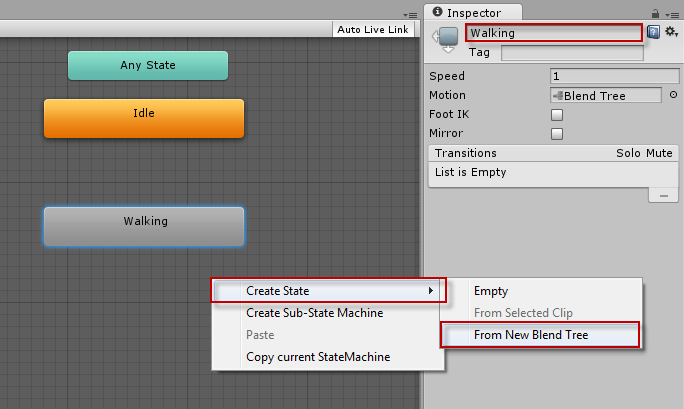
1. Right click a blank spot in the animator view and select “New State->From New Blend Tree”. In the inspector view, name the new state “Walking” (see Figure 18.17).
Figure 18.17. Creating and naming a new state.
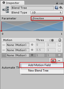
2. Double click the new state to expand it. In the inspector, change the “Parameter” property to “Direction” and add 3 motions by click the plus sign (+) under motions and selecting “Add Motion Field” (see Figure 18.18).
Figure 18.18. Adding motion fields.
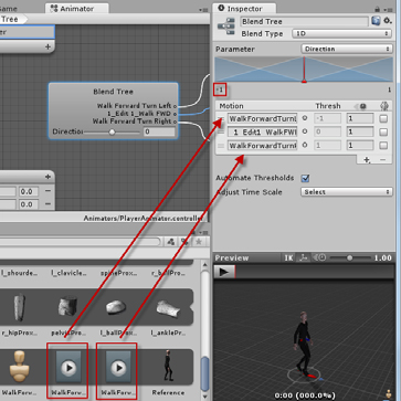
3. Change the minimum value to -1 (see Figure 18.19) and drag each of the three walking animations into the three motion fields. Make sure that they are in the order: “Turn Left”, “Straight”, “Turn Right”. Note that the “walk straight” animation will have a strange name since you never renamed it. You will know which one it is because it should be the only animation clip in the “WalkForward.fbx” file.
Figure 18.19. Changing minimum values and adding animations to a blend tree.
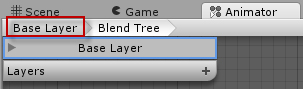
Your walking animation is now ready to blend based on the direction parameter. You can get out of the expanded view by clicking on the “Base Layer” breadcrumb at the top of the animator view (see Figure 18.20).
Figure 18.20. Navigating the animator view.
Transitions
The last thing you will need to do to ensure that your animator is finished is to tell the animator how to transition between the idle and walking animations. You will need to set up two transitions. One transitions the animator from idle to walking, and the other transitions back. To create a transition:
1. Right click on the “Idle” state and select “Make Transition”. This will create a white line that follows your mouse. Click the “Walking” state to connect the two.
2. Repeat step 1, except this time connecting the “Walking” state to the “Idle” state.
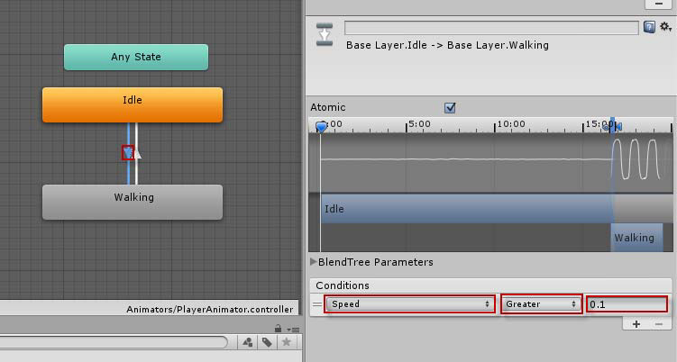
3. Edit the “Idle” to “Walking” transition by clicking the white arrow on it. Set the Conditions to be “Speed” “Greater” than the value 0.1 (see Figure 18.21). Do the same for the walking to idle transition, except set the condition to “Speed” “Less Than” the value 0.1.
Figure 18.21. Modifying transitions.
The animator is finished. You may notice that when you run the scene, there aren’t any working movement animations. This is due to the fact that the speed and direction parameters are never changed. In the next section you will learn how to change these through scripting.
Scripting Animators
Now that everything has been set up with the model, the rigging, the animations, the animator, the transitions, and the blend tree, it is finally time to make the whole thing interactive. Luckily, the actual scripting components are very simple. Most of the hard work was already done in the editor. At this point, all you need to do is manipulate the parameters you created in the animator to get Jack up and running. Since the parameters you set up were of type float, you will need to call the animator method:
SetFloat(<name> , <value>);
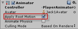
That’s it! If you run your scene after adding this script, you may notice something strange. Not only does jack animate through idle, walking, and turning, but the model also moves. This is due to two factors. The first is that the animations chosen have a built in movement to them. This was done by the animators outside of Unity. If this hadn’t been done, you would have to program the movement yourself. The second factor is that by default the animator allows the animation to move the model. This can be changed in the “Apply Root Motion” property of the animator component (see Figure 18.22).
Figure 18.22. Root motion animator property.
Summary
This hour you worked through creating an animator in Unity. You started by learning about animators. From there you went through the steps of preparing a rigging and animations for use with the Mecanim system. Once that was done, you created an animator. You added parameters, states, a blend tree, and animations to it. You finished by learning how to manipulate the parameters via a script to control the animator.
Q&A
Q. There are a lot of steps here, is the Mecanim system really better than the legacy system?
A. The amount of work this Hour might be daunting. Be aware though that with a little familiarity, these steps become very simple. Furthermore, remember that without the Mecanim system, animations had to be made for specific rigging. In the legacy system you couldn’t remap the rigging like you can now.
Workshop
Take some time to work through the questions here to ensure you have a firm grasp on the material.
Quiz
1. What pose must a model be in to correctly map in the rigging editor?
2. Variables that exist inside an animator are called what?
3. What method is used to set float parameters in a script?
Answers
1. The T-Pose.
2. Ping Pong mode.
3. SetParam( <name>, <value>).
Exercise
There is a lot of information required to produce a robust and high quality animation system. This hour you got to see one way and one group of settings to achieve this. There are plenty of other assets available, however, and learning is paramount to success. Your exercise for this hour is toi continue studying the Mecanim system. Be sure to start by browsing the Unity’s documentation on the system. This can be found on Unity’s website here: http://docs.unity3d.com/Documentation/Manual/MecanimAnimationSystem.html. If you would like to spend some more time learning about the system. Unity has provided a great demo on the system. This demo can be found here: http://video.unity3d.com/video/7362044/unity-40-mecanim-animation-tutorial.