AutoCAD Fundamentals
Part I
Learning Objectives
In this chapter, we introduce AutoCAD and discuss the following:
![]() Introduction and the basic commands
Introduction and the basic commands
![]() The Edit/Modify Objects commands
The Edit/Modify Objects commands
![]() Practicing the Create Objects commands
Practicing the Create Objects commands
![]() Practicing the Edit/Modify Objects commands
Practicing the Edit/Modify Objects commands
By the end of the chapter, you will learn the essential basics of creating, modifying, and viewing objects; the AutoCAD environment; and accuracy in the form of straight lines and precise alignment of geometric objects via OSNAP points.
Estimated time for completion of the chapter, 3 hours.
1.1 Introduction and Basic Commands
AutoCAD 2014 is a very complex program. If you are taking a class or reading this textbook, this is something you probably already know. The commands available to you, along with their submenus and various options, number in the thousands. So, how do you get a handle on them and begin using the software? Well, you have to realize two important facts.
First, you must understand that, on a typical workday, 95% of your AutoCAD drafting time is spent using only 5% of the available commands, over and over again. So getting started is easy; you need to learn only a handful of key commands; and as you progress and build confidence, you can add depth to your knowledge by learning new ones.
Second, you must understand that even the most complex drawing is essentially made up of only a few basic fundamental objects that appear over and over again in various combinations on the screen. Once you learn how to create and edit them, you can draw surprisingly quickly. Understanding these facts is the key to learning the software. We are going to strip away the perceived complexities of AutoCAD and reduce it to its essential core. Let us go ahead now and develop the list of the basic commands.
For a moment, view AutoCAD as a fancy electronic hand-drafting board. In the old days of pencil, eraser, and T-square, what was the simplest thing that you could draft on a blank sheet of paper? That of course is a line. Let us make a list with the following header, “Create Objects,” and below it add “Line.”
So, what other geometric objects can we draw? Think of basic building blocks, those that cannot be broken down any further. A circle qualifies and so does an arc. Because it is so common and useful, throw in a rectangle as well (even though you should note that it is a compound object, made up of four lines). Here is the final list of fundamental objects that we have just come up with:
As surprising as it may sound, these four objects, in large quantities, make up the vast majority of a typical design, so already you have the basic tools. We will create these on the AutoCAD screen in a bit. For now, let us keep going and get the rest of the list down.
Now that you have the objects, what can you do with them? You can erase them, which is probably the most obvious. You can also move them around your screen and, in a similar manner, copy them. The objects can rotate, and you can also scale them up or down in size. With lines, if they are too long, you can trim them, and if they are too short, you can extend them. Offset is a sort of precise copy and one of the most useful commands in AutoCAD. Mirror is used, as the name implies, to make a mirror-image copy of an object. Finally, fillet is used to put a curve on two intersecting lines, among other things. We will learn a few more useful commands a bit later, but for now, under the header “Edit/Modify Objects,” list the commands just mentioned:
Once again, as surprising as it may sound, this short list represents almost the entire set of basic Edit/Modify Objects commands you need once you begin to draft. Start memorizing them.
To finish up, let us add several View Objects commands. With AutoCAD, unlike paper hand drafting, you do not always see your whole design in front of you. You may need to zoom in for a close-up or out to see the big picture. You may also need to pan around to view other parts of the drawing. With a wheeled mouse, so common on computers these days, it is very easy to do both, as we soon see. To this list we add the regen command. It stands for regenerate, and it simply refreshes your screen, something you may find useful later. So here is the list for View Objects:
So, this is it for now, just 17 commands making up the basic set. Here is what you need to do:
1. As mentioned before, memorize them so you know what you have available.
2. Understand the basic idea, if not the details, behind each command. This should be easy to do, because (except for maybe offset and fillet) the commands are intuitive and not cryptic in any way; erase means erase, whether it is AutoCAD, a marker on a whiteboard, or a pencil line.
We are ready now to start AutoCAD, discuss how to interact with the program, and try out all the commands.
1.2 The AutoCAD Environment
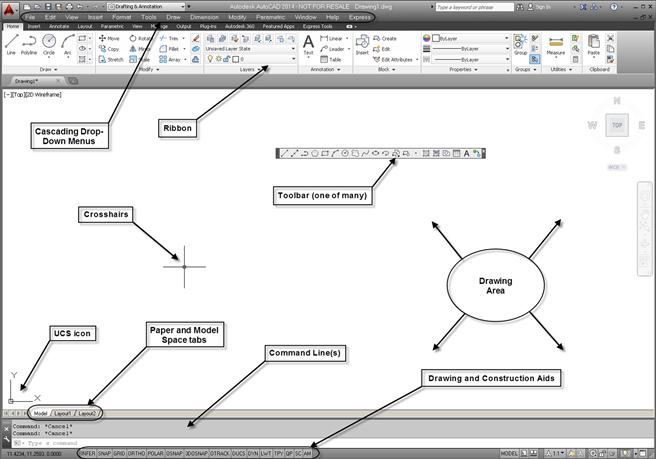
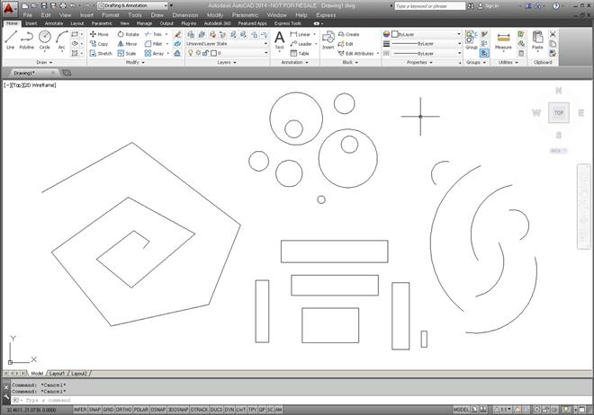
It is assumed that your computer, whether at home, school, work, or training class, is loaded with AutoCAD 2014. It is also assumed that AutoCAD starts up just fine (via the AutoCAD icon or Start menu) and everything is configured right. If not, ask your instructor, as there are just too many things that can go wrong on a particular PC or laptop, and it is beyond the scope of this book to cover these situations. If all is well, start up AutoCAD. You should see the screen depicted in Figure 1.1. Your particular screen’s appearance may vary slightly, which we discuss soon.

This is your basic “out of the box” AutoCAD environment for the Drafting & Annotation workspace. From both the learning and teaching points of view, this screen layout (and the layout of the last few releases) is an improvement over older versions of AutoCAD, and Autodesk has done an admirable job in continuing to keep things clean and (relatively) simple.
Note that you may also see a large panel appear upon AutoCAD startup (it is not shown here). It is the AutoCAD 2014 Welcome panel, a tool for additional functionality and the Help files. We discuss it in Chapter 2, so for now just delete it via the X at the upper right corner. There is a “Display at Startup” check box at the lower left of the panel. If that is left unchecked, you will not see it upon startup anymore. It may be a good idea to leave it as such until we get to talking about this tool.
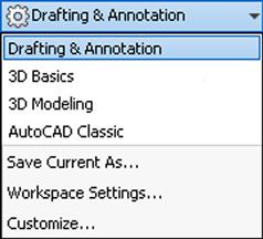
AutoCAD went through a major facelift in recent years, beginning with Release 2009. If you caught a glimpse of earlier versions, you may have noticed toolbars present. They are still around, but what we have now, dominating the upper part of the screen, is called the Ribbon. It is a new way of interacting with AutoCAD, and we discuss it in detail soon. Other screen layouts or workspaces are available to you, including one with toolbars. They can be accessed through the menu seen in Figure 1.2, which is located at the very top line of the screen, depending on settings.
If you click on the down arrow of that menu, you see the workspace switching menu, shown in Figure 1.3. Here, you can switch to AutoCAD Classic if desired, which removes the Ribbon and loads the screen with toolbars and a palette. Give it a try. So, which workspace to use? Well, for now switch back to the Drafting & Annotation workspace (seen being selected in Figure 1.3).
Next, let us take a tour of the features you are looking at on the screen, as shown in Figure 1.4. The following is a brief description of what is labeled. Be sure to read each description carefully, as the AutoCAD environment has been altered slightly out of necessity and will remain this way for the rest of the textbook. What has been added or changed (and why) is detailed in this bulleted list:
![]() Drawing Area: The drawing area takes up most of the screen and is colored a dark gray in the default version of the environment. This is where you work and your design appears. It is best to change the drawing area to black to ease eye strain, as less light will radiate toward you. In this textbook, however (as in most textbooks), the color will always be white to conserve ink and for clarity on a printed page. If you wish to change the color of the drawing area, you need to right-click into Options…, choose the Display tab, then Colors…. Finally, change the color from the drop-down menu on the right. We cover all this in more detail in Chapter 14, so you should ask your instructor for assistance in the meantime, if necessary. One new change for 2014 is that the drawing area now has “tabs,” visible at the upper left, that allow you to cycle through multiple drawings.
Drawing Area: The drawing area takes up most of the screen and is colored a dark gray in the default version of the environment. This is where you work and your design appears. It is best to change the drawing area to black to ease eye strain, as less light will radiate toward you. In this textbook, however (as in most textbooks), the color will always be white to conserve ink and for clarity on a printed page. If you wish to change the color of the drawing area, you need to right-click into Options…, choose the Display tab, then Colors…. Finally, change the color from the drop-down menu on the right. We cover all this in more detail in Chapter 14, so you should ask your instructor for assistance in the meantime, if necessary. One new change for 2014 is that the drawing area now has “tabs,” visible at the upper left, that allow you to cycle through multiple drawings.
![]() Command Line(s): Right below the drawing area is the command line or, by default, two lines. This is where the commands may be entered and also where AutoCAD tells you what it needs to continue. Always keep an eye on what appears here, as this is one of the main ways that AutoCAD communicates with you. Although we discuss a newer “heads-up” on-screen interaction method in Chapter 2, the command line remains very relevant. It is colored gray and white by default but can be changed (in a manner similar to the drawing area) to all white if desired. We leave the color as default. It has been stretched upwards to include three lines for clarity, however. These are all minor details, so you can leave your command line completely “as is” if you wish.
Command Line(s): Right below the drawing area is the command line or, by default, two lines. This is where the commands may be entered and also where AutoCAD tells you what it needs to continue. Always keep an eye on what appears here, as this is one of the main ways that AutoCAD communicates with you. Although we discuss a newer “heads-up” on-screen interaction method in Chapter 2, the command line remains very relevant. It is colored gray and white by default but can be changed (in a manner similar to the drawing area) to all white if desired. We leave the color as default. It has been stretched upwards to include three lines for clarity, however. These are all minor details, so you can leave your command line completely “as is” if you wish.
![]() UCS Icon: This is a basic X-Y-Z (Z is not visible) grid symbol. It will be important later in advanced studies and 3D. It can be turned off, as is shown via a tip in a later chapter. The significance of this icon is great, and we study it in detail later on. For now, just observe that the Y axis is “up” and the X axis is “across.”
UCS Icon: This is a basic X-Y-Z (Z is not visible) grid symbol. It will be important later in advanced studies and 3D. It can be turned off, as is shown via a tip in a later chapter. The significance of this icon is great, and we study it in detail later on. For now, just observe that the Y axis is “up” and the X axis is “across.”
![]() Paper Space/Model Space Tabs: These Model/Layout1/Layout2 tabs, not unlike those used in Microsoft’s Excel, indicate which drawing space you are in and are important in Chapter 10 when we cover Paper Space. Though you can click on them to see what happens, be sure to return to the Model tab to continue further.
Paper Space/Model Space Tabs: These Model/Layout1/Layout2 tabs, not unlike those used in Microsoft’s Excel, indicate which drawing space you are in and are important in Chapter 10 when we cover Paper Space. Though you can click on them to see what happens, be sure to return to the Model tab to continue further.
![]() Toolbar: Toolbars contain icons that can be pressed to activate commands. They are an alternative to typing and the Ribbon, and most commands can be accessed this way. AutoCAD 2014 has dozens of them. You may not have a toolbar present on your screen at the moment. If that is the case, do not worry, we activate a few toolbars shortly.
Toolbar: Toolbars contain icons that can be pressed to activate commands. They are an alternative to typing and the Ribbon, and most commands can be accessed this way. AutoCAD 2014 has dozens of them. You may not have a toolbar present on your screen at the moment. If that is the case, do not worry, we activate a few toolbars shortly.
![]() Crosshairs: Crosshairs are simply the mouse cursor and move around along with the movements of your mouse. They can be full size and span the entire screen or a small (flyspeck) size. You can change the size of the crosshairs if you wish, and full screen is recommended in some cases. For now, we leave it as is.
Crosshairs: Crosshairs are simply the mouse cursor and move around along with the movements of your mouse. They can be full size and span the entire screen or a small (flyspeck) size. You can change the size of the crosshairs if you wish, and full screen is recommended in some cases. For now, we leave it as is.
![]() Drawing & Construction Aids: These various settings assist you in drafting and modeling. We introduce them as necessary. By default, these aids are in graphical symbol form and some may be activated, which you can determine by observing their color. If they are off, they are gray; if on, then light blue. Be sure to turn them all to off for now. We will activate them as needed. There is also one more significant difference here. All the drawing aids have been converted from icon symbols to written symbols. The reason for this is that it is easier for new students to just read them and use them; no additional memorization of what the symbols mean is needed, only knowledge of how to use them. If you wish to do the same, right-click on any of them and uncheck “Use Icons.” If you prefer them as icons, then leave them as is, but they are converted for the remainder of this textbook. Note that there are additional drawing and construction aids all the way to the far right, on the same band. We discuss them later in the text, as needed.
Drawing & Construction Aids: These various settings assist you in drafting and modeling. We introduce them as necessary. By default, these aids are in graphical symbol form and some may be activated, which you can determine by observing their color. If they are off, they are gray; if on, then light blue. Be sure to turn them all to off for now. We will activate them as needed. There is also one more significant difference here. All the drawing aids have been converted from icon symbols to written symbols. The reason for this is that it is easier for new students to just read them and use them; no additional memorization of what the symbols mean is needed, only knowledge of how to use them. If you wish to do the same, right-click on any of them and uncheck “Use Icons.” If you prefer them as icons, then leave them as is, but they are converted for the remainder of this textbook. Note that there are additional drawing and construction aids all the way to the far right, on the same band. We discuss them later in the text, as needed.
![]() Ribbon: This is a relatively new way of interacting with AutoCAD’s commands, to be discussed soon. The Ribbon first appeared in AutoCAD 2009 and is somewhat similar to the approach used in Microsoft Word, Excel, and PowerPoint.
Ribbon: This is a relatively new way of interacting with AutoCAD’s commands, to be discussed soon. The Ribbon first appeared in AutoCAD 2009 and is somewhat similar to the approach used in Microsoft Word, Excel, and PowerPoint.
![]() Cascading Drop-down Menus: This is another way to access commands in AutoCAD. These menus, so named because they drop out like a waterfall, may be hidden initially, but you can easily make them visible via the down arrow at the very top of the screen, to the right of Drafting & Annotation (visible in Figure 1.2). A lengthy menu appears. Select “Show Menu Bar” toward the bottom, and the cascading menus appear as a band across the top of the screen, above the Ribbon. You should keep these menus in their spot from now on; they are referred to often.
Cascading Drop-down Menus: This is another way to access commands in AutoCAD. These menus, so named because they drop out like a waterfall, may be hidden initially, but you can easily make them visible via the down arrow at the very top of the screen, to the right of Drafting & Annotation (visible in Figure 1.2). A lengthy menu appears. Select “Show Menu Bar” toward the bottom, and the cascading menus appear as a band across the top of the screen, above the Ribbon. You should keep these menus in their spot from now on; they are referred to often.
Review this bulleted list carefully; it contains a lot of useful “get to know AutoCAD” information. You do not have to change your environment exactly as suggested—how you like your AutoCAD to look, after all, is personal taste to some extent. However, be sure to understand how to do it if necessary and why the look of AutoCAD is the way it is in the textbook.
1.3 Interacting with AutoCAD
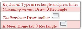
OK, so you have the basic commands in hand and ideally a good understanding of what you are looking at on the AutoCAD screen. We are ready to try out the basic commands and eventually draft something. So, how do we interact with AutoCAD and tell it what we want drawn? There are four primary ways (Methods 1–4), which follow, roughly in the order they appeared over the years. There are also two outdated methods, called the tablet and the screen side menu (dating back to the very early days of AutoCAD), but we do not cover them.
Method 1. Type in the commands on the command line (AutoCAD v1.0–current).
Method 2. Select the commands from the drop-down cascading menus (AutoCAD v1.0–current).
Method 3. Use toolbar icons to activate the commands (AutoCAD 12/13–current).
Method 4. Use the Ribbon tabs, icons, and menus (AutoCAD 2009–current).
Details of each method including the pros and cons follow. Most commands are presented in all four primary ways, and you can experiment with each method to determine what you prefer. Eventually, you will settle on one particular way of interacting with AutoCAD or a hybrid of several.
Method 1. Type in the Commands on the Command Line
This was the original method of interacting with AutoCAD and, to this day, remains the most foolproof way to enter a command: good old-fashioned typing. AutoCAD is unique among leading CAD software in that it has retained this method while almost everyone else moved to graphic icons, toolbars, and Ribbons. If you hate typing, this will probably not be your preferred choice.
However, do not discount keyboard entry entirely; AutoCAD has kept it for a reason. When the commands are abbreviated to one or two letters (Line=L, Arc=A, etc.), input can be incredibly fast. Just watch a professional typist for proof of the speed with which one can enter data via a keyboard. Other advantages to typing are that you no longer have toolbars or a Ribbon cluttering up precious screen space (there is never enough of it), and you no longer have to take your eyes off the design to find an icon; instead, the command is literally at your fingertips. The disadvantage is of course that you have to type.
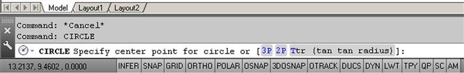
To use this method, simply type in the desired command (spelling counts!) at the command line, as seen in Figure 1.5, and press Enter. The sequence initiates and you can proceed. A number of shortcuts are built into AutoCAD (try using just the first letter or two of a command), and we learn how to make our own shortcuts in advanced chapters. This method is still preferred by many “legacy” users (a kind way to say they have been using AutoCAD forever). Note that AutoCAD has an AutoComplete (as well as an AutoCorrect) feature on the command line, which calls up a possible list of commands based on just the first letter or two. This can be useful as you start out your learning the software but can also be turned off via a command line right-click option under Input Settings.
Method 2. Select the Commands from the Drop-down Cascading Menus
This method has also been around since the beginning. It presents a way to access virtually every AutoCAD command, and indeed many students start out by checking out every one of them as a crash course on what is available—a fun but not very effective way of learning AutoCAD.
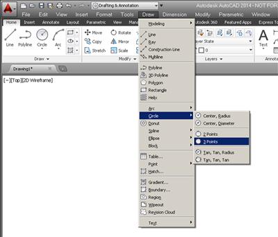
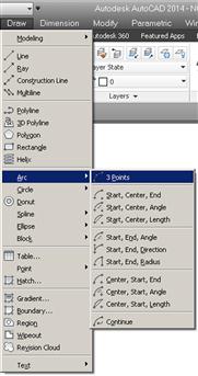
Go ahead and examine the cascading menus; these are similar in basic arrangement to other software, and you should be able to navigate through them easily. We refer to them on occasion in the following format: Menu→Command. So, for the sequence shown in Figure 1.6, you would read Draw→Circle→3 Points. The underlined letters are “hot keys” that you can press to choose that option while running through the menu.
Method 3. Use Toolbar Icons to Activate the Commands
This method has been around since AutoCAD switched from DOS to Windows in the mid-1990s and is a favorite of a whole generation of users; toolbars are a familiar sight with virtually any software these days. Toolbars contain sets of icons (see Figure 1.7 for an example), organized by categories (Draw toolbar, Modify toolbar, etc.). You press the icon you want, and a command is initiated. One disadvantage to toolbars, and the reason the Ribbon was developed, is that they take up a lot of space and, arguably, are not the most effective way of organizing commands on the screen.
You can access some toolbars by activating the AutoCAD Classic Workspace or all of them at any time by simply selecting Tools→Toolbars→AutoCAD from the cascading menus. When you do that, a menu will appear (Figure 1.8), and you can simply check off the ones you want or do not want. You also can access the same menu by right-clicking on any of the toolbars themselves. Once you have a few up, you typically just dock them on top or off to the side. It is highly encouraged to bring up the Standard, Draw, and Modify toolbars for learning purposes. We do not require any other ones for now but will just bring them up as the need arises.

Method 4: Use the Ribbon Tabs, Icons, and Menus
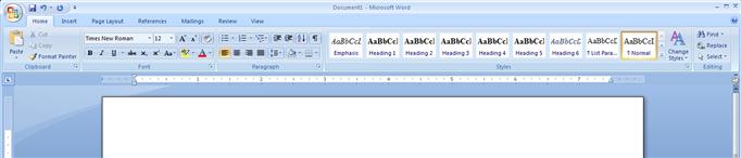
This is the most recently introduced method of interacting with AutoCAD and follows a new trend in software user interface design, such as that used by Microsoft and its Office 2007 and 2010 (seen in Figure 1.9 with Word®). Notice how toolbars have been displaced by “tabbed” categories (Home, Insert, Page Layout, etc.), where information is grouped together by a common theme. So it goes with the new AutoCAD. The Ribbon was introduced with AutoCAD 2009, and it is here to stay. It is shown again by itself in Figure 1.10.
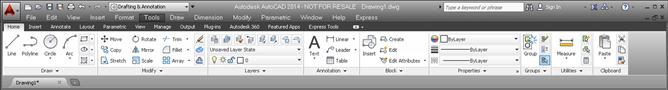
Notice what we have here. A collection of tabs, indicating a subject category, is found at the top (Home, Insert, Annotate, etc.), and each tab reveals an extensive set of tools (Draw, Modify, Annotation, etc.). At the bottom of the Ribbon, additional options can be found by using the drop arrows. In this manner, the toolbars have been rearranged in what is, in principle, a more logical and space-saving manner.
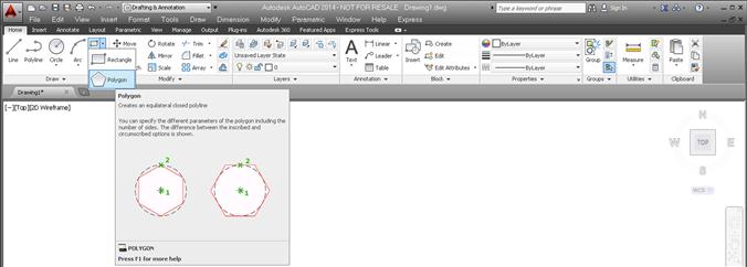
Additionally, tool tips appear if you place your mouse over any particular tool for more than a second. Another second yields an even more detailed tool tip. In Figure 1.11, you see the Home tab selected, followed by additional options via the drop arrow, and finally the mouse placed over the polygon command. A few moments of waiting reveals the full tool tip; pressing the icon activates the command.
Familiarize yourself with the Ribbon by exploring it. It presents some layout advantages, and specialized Ribbons can be displayed via other workspaces. The disadvantage of this new method is that it is a relatively advanced tool that presents many advanced features right away and some confusion is liable to come up for a brand-new user. It is also not ideal for longtime users who type, and some veterans in my update classes turn the feature off. The Ribbon is the single biggest change to AutoCAD’s user interface and represents a jump forward in user/software interaction, but the ultimate decision to use it is up to you.
Before we try out our basic commands, let us begin a list of tips. These are a mix of good ideas, essential habits, and time-saving tricks passed along to you every once in a while (mostly in the first few chapters). Make a note of them as they are important. Here is the first, most urgently needed one.
In the interest of trying out not just the Ribbon but also toolbars, cascading menus, and typing while learning the basics, bring up the three toolbars mentioned earlier, Standard, Draw, and Modify, shutting off all the rest. This is the setup you see in all the upcoming AutoCAD screen shots. Finally, close out any floating palettes and, if you wish, remove your scroll bars (ask your instructor how). They take up room and are not an efficient way to get around the screen—we learn far more effective pan and zoom methods soon. Review everything learned thus far and proceed to the first commands.
1.4 Practicing the Create Objects Commands
Let us try the commands now, one by one. Although it may not be all that exciting, it is extremely important that you memorize the sequence of prompts for each command, as these are really the ABCs of AutoCAD.
Remember: If a command is not working right, or you see little blue squares (they are called grips, and we cover them very soon), just press Esc to get back to the Command: status line, at which point you can try it again. All four methods of command entry are presented: typing, cascading menus, toolbar icons, and the Ribbon. Alternate each method until you decide which one you prefer. It is perfectly OK to use a hybrid of methods.
Line
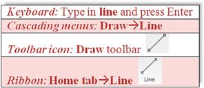
Step 1. Begin the line command via any of the preceding methods.
![]() AutoCAD says: Specify first point:
AutoCAD says: Specify first point:
Step 2. Using the mouse, left-click anywhere on the screen.
![]() AutoCAD says: Specify next point or [Undo]:
AutoCAD says: Specify next point or [Undo]:
Step 3. Move the mouse elsewhere on the screen and left-click again. You can repeat Step 2 as many times as you wish. When you are done, click Enter or Esc. You should have a bunch of lines on your screen, either separate or connected together, as shown in Figure 1.12.
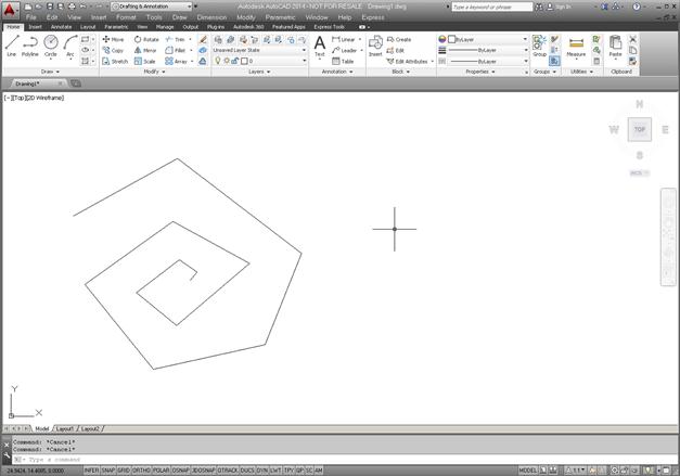
You need not worry about several things at this point. The first is accuracy; we introduce a tremendous amount of accuracy later in the learning process. The second is the options available in the brackets, such as [Undo]; we cover those as necessary. What is important is that you understand how you got those lines and how to do it again. In a similar manner, we move on to the other commands.
Circle
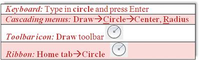
Step 1. Begin the circle command via any of the preceding methods.
![]() AutoCAD says: Specify center point for circle or [3P/2P/Ttr (tan tan radius)]:
AutoCAD says: Specify center point for circle or [3P/2P/Ttr (tan tan radius)]:
Step 2. Using the mouse, left-click anywhere on the screen and move the mouse out away from that point.
![]() AutoCAD says: Specify radius of circle or [Diameter]<1.9801>:
AutoCAD says: Specify radius of circle or [Diameter]<1.9801>:
Notice the circle that forms; it varies in size with the movement of your mouse. The value in brackets may of course be different in your case.
Step 3. Left-click to finish the circle command. Repeat Steps 1 through 3 several times, and your screen should look like Figure 1.13.
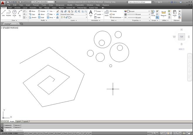
The method just used to create the circle was called Center, Radius, and you could specify an exact radius size if you wish, by just typing in a value after the first click (try it). As you may imagine, there are other ways to create circles—six ways to be precise, as seen with the Ribbon and cascading menus (Figures 1.14 and 1.15).
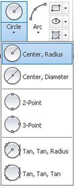
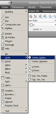
Special attention should be paid to the Center, Diameter option. Often students are asked to create a circle of a certain diameter, and they inadvertently use radius. This is less of a problem when using the Ribbon or the cascading menus, but you need to watch out if typing or using toolbars, as you will need to press d for [Diameter] before entering a value; otherwise, guess what it will be. We focus much more on these bracketed options as the course progresses. You get a chance to practice the other circle options as part of the end of chapter exercises.
Arc
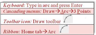
Step 1. Begin the arc command via any of the preceding methods.
![]() AutoCAD says: Specify start point of arc or [Center]:
AutoCAD says: Specify start point of arc or [Center]:
Step 2. Left-click with the mouse anywhere on the screen. This is the first of three points necessary for the arc.
![]() AutoCAD says: Specify second point of arc or [Center/End]:
AutoCAD says: Specify second point of arc or [Center/End]:
Step 3. Click somewhere else on the screen to place the second point.
![]() AutoCAD says: Specify end point of arc:
AutoCAD says: Specify end point of arc:
Step 4. Left-click a third (final) time, somewhere else on the screen, to finish the arc.
Practice this sequence several more times to fully understand the way AutoCAD places the arc. Your screen should look something like Figure 1.16.

The method just used to create the arcs is called 3 Point and, without invoking other options, is a rather arbitrary (eyeball) method of creating them, which is just fine for some applications. Just as with circles, there are, of course, other ways to create arcs—11 ways to be precise, as seen with the Ribbon and cascading menus (Figures 1.17 and 1.18).
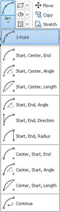
Not all of these options are used, and some you will probably never need, but it is worth going over them to know what is available. You get a chance to practice the other arc options as part of the end of chapter exercises.
Rectangle
Step 1. Begin the rectangle command via any of the preceding methods.
![]() AutoCAD says: Specify first corner point or [Chamfer/Elevation/Fillet /Thickness/Width]:
AutoCAD says: Specify first corner point or [Chamfer/Elevation/Fillet /Thickness/Width]:
Step 2. Left-click, and move the mouse diagonally somewhere else on the screen.
![]() AutoCAD says: Specify other corner point or [Area/Dimensions/Rotation]:
AutoCAD says: Specify other corner point or [Area/Dimensions/Rotation]:
Step 3. Left-click one more time to finish the command. Your screen should look more or less like Figure 1.19.
There are of course more precise ways to draw a rectangle. In Step 3, you can press d for Dimensions and follow the prompts to assign length, width, and a corner point (where you want it) to your rectangle. Try it out, but as with all basic shapes drawn so far, do not worry too much about sizing and accuracy, just be sure to understand and memorize the sequences for the basic command—that is what is important for now.
So, now you have created the four basic shapes used in AutoCAD drawings (and ended up with a lot of junk). Let us erase all of them, and get back to a blank screen. To do this, we need to introduce Tip 2, which is quite easy to just type. Notice the use of the e abbreviation; we will see more of this as we progress.
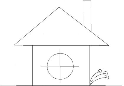
So, let us put all of this to good use. Create the drawing shown in Figure 1.20. Use the rectangle, line, circle, and arc commands. Do not get caught up trying to make everything line up perfectly, just do a quick sketch. Then, you can tell everyone that you learned how to draw a house in AutoCAD within the first half hour. Well, sort of.
At this point it is necessary to mention the zoom and pan commands. These are very easy if you have a mouse with a center wheel (as most PCs do these days).
1.5 View Objects
Zoom
Put your finger on the mouse wheel and turn it back and forth without pressing down. The house you just created gets smaller (roll back) or larger (roll forward) on the screen. Remember though, the object remains the same; just your view is zooming in and out.
Pan
Put your finger on the mouse wheel, but this time press and hold. A hand symbol appears. Now move the mouse around while keeping the wheel depressed. You are able to pan around your drawing. Remember again, the drawing is not moving; you are moving around it.
Regen
This is the easiest command you will learn. Just type in regen and press Enter. The screen refreshes. One use for this is if you are panning over and AutoCAD does not let you go further, as if you hit a wall. Simply regen and proceed.
While the mouse method is easiest, there are other ways to zoom and pan. One alternative is using toolbars, and part of the Standard toolbar (which you should have on your screen) has some Zoom (magnifying glass) and Pan (hand) icons for this purpose, as seen in Figure 1.21.
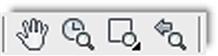
Explore the icon options on your own, but one particular zoom option is critically important: Zoom to Extents. If you managed to pan your little house right off the screen and cannot find it, this comes in handy, and a full tip on Zoom to Extents is presented next.
What if you did something that you did not want to do and wished you could go back a step or two? Well, like most programs, AutoCAD has an undo command, which brings us to the fourth tip.
Now that you have drawn your house, leave it on your screen and let us move on. We now have to go through all the Edit/Modify Objects commands, one by one. Each of them is critical to creating even the most basic drawings, so go through each carefully, paying close attention to the steps involved. Along the way, the occasional tip is added as the need arises.
Just to remind you: The Esc key gets you out of any mistakes you make and returns you to the basic command line. Be sure to perform each sequence several times to really memorize it. As you learn the first command, erase, you also are introduced to the picking objects selection method, which is similar throughout the rest of the commands. Also, keep a close eye on the command line, as it is where you and AutoCAD communicate for now, and it is a two-way conversation.
Finally, before you get started, here is another useful tip that students usually appreciate early on to save some time and effort.
1.6 Practicing the Edit/Modify Objects Commands
Erase
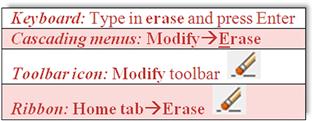
Step 1. Begin the erase command via any of the preceding methods.
Step 2. Select any object from the house in the previous drawing assignment (Figure 1.20) by taking the mouse, positioning it over that object (not in the empty space), and left-clicking once.
![]() AutoCAD says: Select objects: 1 found. The object becomes dashed. You saw this before when we erased everything in Tip 2. It means the objects were selected. AutoCAD continues to ask you: Select objects: Watch out for this step. AutoCAD always asks this, in case you want to select more objects, so get used to it. You are done, however, so….
AutoCAD says: Select objects: 1 found. The object becomes dashed. You saw this before when we erased everything in Tip 2. It means the objects were selected. AutoCAD continues to ask you: Select objects: Watch out for this step. AutoCAD always asks this, in case you want to select more objects, so get used to it. You are done, however, so….
Practice this several times, using the undo command to bring the object back. Make sure you keep it there, since you need it to practice the next few commands. You can of course select more than one object, as this is the whole point of being asked to select again. As you click on each one, it becomes dashed. You can do this until you run out of objects to select; there is no limit. To deselect any objects, hold down the Shift key and click on them. They will be removed from the selection set.
Move
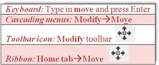
Step 1. Begin the move command via any of the preceding methods.
Step 2. Select an object by positioning the mouse over that object (not the empty space) and left-clicking once.
![]() AutoCAD says: Select objects: 1 found. The object becomes dashed.
AutoCAD says: Select objects: 1 found. The object becomes dashed.
![]() AutoCAD then asks you again: Select objects:
AutoCAD then asks you again: Select objects:
Step 3. Unless you have more than one object to move, you are done, so press Enter.
![]() AutoCAD says: Specify base point or [Displacement]<Displacement>:
AutoCAD says: Specify base point or [Displacement]<Displacement>:
Step 4. Left-click anywhere on or near the object to “pick it up;” this is where you are moving it from.
![]() AutoCAD says: Specify second point or<use first point as displacement>:
AutoCAD says: Specify second point or<use first point as displacement>:
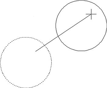
Step 5. Move the mouse somewhere else on the screen and left-click to place the object in the new location. This is where you are moving it to.
Undo what you just did and practice it again. Figure 1.22 shows the move command in progress. Notice how the dashed circle remains there as a “shadow” until you place your circle in its new location.
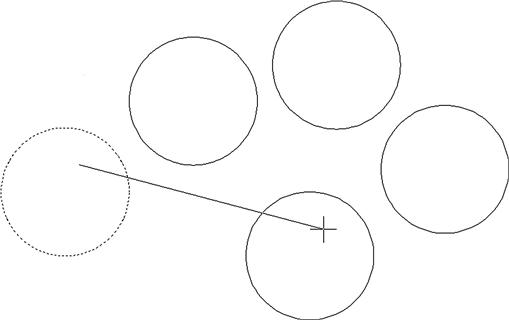
Copy
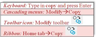
Step 1. Begin the copy command via any of the preceding methods.
Step 2. Select an object by positioning the mouse over that object and left-clicking once.
![]() AutoCAD says: Select objects: 1 found. The object becomes dashed.
AutoCAD says: Select objects: 1 found. The object becomes dashed.
![]() AutoCAD then asks you again: Select objects:
AutoCAD then asks you again: Select objects:
Step 3. Unless you have more than one object to copy, you are done, so press Enter.
![]() AutoCAD says: Specify base point or [Displacement/mOde]<Displacement>:
AutoCAD says: Specify base point or [Displacement/mOde]<Displacement>:
Step 4. Left-click anywhere on or near the object to “pick it up”; this is where you are copying it from.
![]() AutoCAD says: Specify second point or<use first point as displacement>:
AutoCAD says: Specify second point or<use first point as displacement>:
Step 5. Move the mouse somewhere else on the screen and left-click to copy the object to the new location. This is where you are copying it to. Notice that a dashed copy of the object remains in its original location until you complete the command. You can copy as many times as you want.
Undo what you just did and practice it again. Figure 1.23 shows the copy command in progress. The dashed circle remains there as a “shadow” until you copy your new circles into their new locations.
Rotate
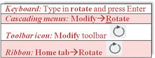
Step 1. Begin the rotate command via any of the preceding methods.
![]() AutoCAD says: Current positive angle in UCS: ANGDIR=counterclockwise ANGBASE=0, and on the next line: Select objects:
AutoCAD says: Current positive angle in UCS: ANGDIR=counterclockwise ANGBASE=0, and on the next line: Select objects:
Step 2. Select any object as before, remembering to press Enter again after the selection. So far, it is quite similar to erase, move, and copy.
![]() AutoCAD says: Specify base point: This means select the pivot point of the object’s rotation (the point about which it rotates). If you select a circle for your object, try to stay away from the center point, as your rotation efforts may be less than obvious.
AutoCAD says: Specify base point: This means select the pivot point of the object’s rotation (the point about which it rotates). If you select a circle for your object, try to stay away from the center point, as your rotation efforts may be less than obvious.
Step 3. Click anywhere on or near the selected object.
![]() AutoCAD says: Specify rotation angle or [Copy/Reference]<0>:
AutoCAD says: Specify rotation angle or [Copy/Reference]<0>:
Step 4. Move the mouse around in a wide circle and the object rotates. Notice how the motion gets smoother as you move the mouse farther away. You can click anywhere for a random rotation angle or you can type in a specific numerical degree value.
Figure 1.24 shows the rotate command in progress.
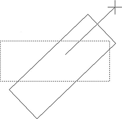
Scale
Step 1. Begin the scale command via any of the preceding methods.
Step 2. Select any object as before, remembering to press Enter again after the first selection.
![]() AutoCAD says: Specify base point: This means select the point from which the scaling of the object (up or down) is to occur.
AutoCAD says: Specify base point: This means select the point from which the scaling of the object (up or down) is to occur.
Step 3. Click somewhere on or near the object or directly in the middle of it.
![]() AutoCAD says: Specify scale factor or [Copy/Reference]<1.000>:
AutoCAD says: Specify scale factor or [Copy/Reference]<1.000>:
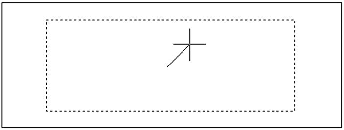
Step 4. Move the mouse around the screen. The object gets bigger or smaller. You can randomly scale it or enter a numerical value. For example, if you want it twice as big, enter 2; half size is .5.
Figure 1.25 shows the scale command in progress.
Trim
To practice this command you first need to draw two intersecting lines, one horizontal and one vertical, similar to a plus sign (see Figure 1.26). Once this is done, go ahead and perform the sequence that follows.
Step 1. Begin the trim command via any of the preceding methods.
Current settings: Projection=UCS, Edge=None
Select objects or<select all>:
Step 2. Left-click on one of the lines. You can choose the vertical or horizontal, it does not matter. This is your cutting edge. The other line, the one you did not pick, is trimmed at the intersection point of the two lines. The cutting edge line becomes dashed.
![]() AutoCAD says: Select objects or<select all>: 1 found
AutoCAD says: Select objects or<select all>: 1 found
![]() AutoCAD says: Select object to trim or shift-select to extend or[Fence/Crossing/Project/Edge/eRase/Undo]:
AutoCAD says: Select object to trim or shift-select to extend or[Fence/Crossing/Project/Edge/eRase/Undo]:
Step 4. Go ahead and pick anywhere on the line that you did not yet select and it is trimmed.
You can repeat Step 4 as many times as you want, but we are done, so press Enter. Practice this several times by pressing u then Enter and repeating Steps 1 through 4. Remember two things to avoid mistakes: Pick the cutting edge first, and do not forget to press Enter before picking the line to be chopped.
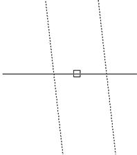
You can also do a trim between two or more lines, as shown in Figure 1.26. This is something we need in the first major project, so practice both types of trims. In both cases, the lines selected as cutting edges are now dashed, and the lines about to be trimmed have the cursor (small box) over them.
Extend
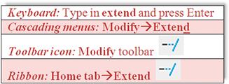
To practice this command, we first need to draw two intersecting lines, just as for trim, but then use the move command to relocate the vertical line directly to the right (or left) of the horizontal line, a short distance away, so we can extend the horizontal line into the vertical. You can see this in Figure 1.27. Once this is done, go ahead and perform the extend command.
Step 1. Begin the extend command via any of the preceding methods.
Current settings: Projection=UCS, Edge=None
Select objects or<select all>:
Step 2. At this point, left-click on the vertical line. This is the target into which you extend the horizontal line. It becomes dashed.
![]() AutoCAD says: Select objects: 1 found
AutoCAD says: Select objects: 1 found
![]() AutoCAD says: Select object to extend or shift-select to trim or [Fence/Crossing/Project/Edge/Undo]:
AutoCAD says: Select object to extend or shift-select to trim or [Fence/Crossing/Project/Edge/Undo]:
Step 4. Pick the end of the horizontal line that is closest to the vertical line. The arrow is what extends into the vertical line target.
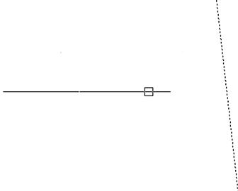
You can repeat Step 4 as many times as you want, but we are done, so press Enter. Practice this several times by pressing u then Enter and repeating Steps 1 through 4. In Figure 1.27, the dashed vertical line is the “target” and the solid horizontal line is the “arrow.” The cursor (box) is positioned to extend the arrow into the target by clicking once.
Offset
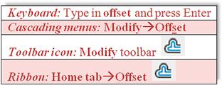
This command is one of the more important ones you will learn. Its power lies in its simplicity. This command creates new lines by the directional parallel offset concept, where if you have a line on your screen, you can create a new one that is a certain distance away but parallel to the original. To illustrate it, first draw a random vertical or horizontal line anywhere on your screen.
Step 1. Begin the offset command via any of the preceding methods.
![]() AutoCAD says: Specify offset distance or [Through/Erase/Layer]<Through>:
AutoCAD says: Specify offset distance or [Through/Erase/Layer]<Through>:
Step 2. Enter an offset value (use a small number for now, 2 or 3). Then press Enter.
![]() AutoCAD says: Select object to offset or [Exit/Undo]<Exit>:
AutoCAD says: Select object to offset or [Exit/Undo]<Exit>:
Step 3. Pick the line by left-clicking on it; the line becomes dashed.
![]() AutoCAD says: Specify point on side to offset or [Exit/Multiple/Undo]<Exit>:
AutoCAD says: Specify point on side to offset or [Exit/Multiple/Undo]<Exit>:
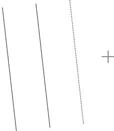
Step 4. Pick a direction for the line to go, which is to one of the two sides of the original line. It does not matter exactly how far away from the original line you click, as the distance has already been specified. You can keep doing this over and over by selecting the new line then the direction (see Figure 1.28). If you want to change the offset distance, you must repeat Steps 1 and 2.
The significance of the offset command may not be readily apparent. Many students, especially ones who may have done some hand drafting, come into learning AutoCAD with the preconceived notion that it is just a computerized version of pencil and paper. While this is true in some cases, in others, AutoCAD represents a radical departure. When you begin a new drawing on paper, you literally draw line after line. With AutoCAD, surprisingly little line drawing occurs. A few are drawn, and then the offset command is employed throughout. Learn this command well, you will need it.
Mirror
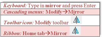
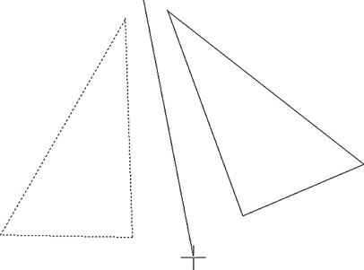
This command, much as the name implies, creates a mirror copy of an object over some plane. It is surprisingly useful because often just copying and rotating is not sufficient or takes too many steps. To learn this command, you have to think of a real-life mirror, with you standing in front of it. The original object is you, the plane is the door with the mirror attached (which can swing on a hinge), and the new object is your mirrored reflection. To practice this command, draw a triangle by joining three lines together, as seen in Figure 1.29.
Step 1. Begin the mirror command via any of the preceding methods.
Step 2. Select all three lines of the triangle and press Enter.
![]() AutoCAD says: Specify first point of mirror line:
AutoCAD says: Specify first point of mirror line:
Step 3. Click anywhere near the triangle and move the mouse around. You notice the new object appears to be anchored by one point. This is the swinging mirror reflection.
![]() AutoCAD says: Specify second point of mirror line:
AutoCAD says: Specify second point of mirror line:
Step 4. Click again near the object (make the second click follow an imaginary straight line down). You notice the new object disappear. Do not panic; rather check what the command line says.
![]() AutoCAD says: Delete source objects? [Yes/No]<N>:
AutoCAD says: Delete source objects? [Yes/No]<N>:
Step 5. The response in Step 4 just asked you if you want to keep the original object. If you do (the most common response), then just press Enter and you are done. Figure 1.29 illustrates Step 3.
Fillet
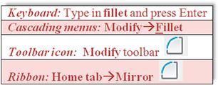
Fillets are all around us. This is not just an AutoCAD concept but rather an engineering description for a rounded edge on a corner of an object or at an intersection of two objects. These edges are added to avoid sharp corners for safety or other technical reasons (such as a weld). By definition, a fillet needs to have a radius greater than zero; but in AutoCAD, a fillet can have a radius of zero, allowing for some useful editing, as we see soon. To illustrate this command, first draw two perpendicular lines that intersect, as seen in the first box of Figure 1.30.
Step 1. Begin the fillet command via any of the preceding methods.
Current settings: Mode=TRIM, Radius=0.0000
Select first object or [Undo/Polyline/Radius/Trim/Multiple]:
Step 2. Put a radius on the fillet. Type in r for radius and press Enter.
![]() AutoCAD says: Specify fillet radius<0.0000>:
AutoCAD says: Specify fillet radius<0.0000>:
Step 3. Enter a small value, perhaps 0.5 or 1. Press Enter.
![]() AutoCAD says: Select first object or [Undo/Polyline/Radius/Trim/Multiple]:
AutoCAD says: Select first object or [Undo/Polyline/Radius/Trim/Multiple]:
Step 4. Select the first (horizontal) line, somewhere near the intersection. It becomes dashed.
![]() AutoCAD says: Select second object or shift-select to apply corner or [Radius]:
AutoCAD says: Select second object or shift-select to apply corner or [Radius]:
Step 5. As your mouse moves toward the second (vertical) line, you see a preview of the resulting fillet (if the fillet is valid). This preview capability is a new feature, first seen with AutoCAD 2012. Go ahead and click on the second line somewhere near the intersection; a fillet of the radius you specified is added.
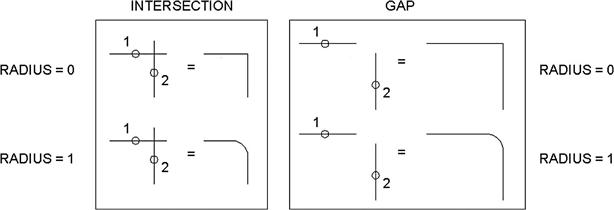
These are the steps involved in adding a fillet with a radius. You can also do a fillet with a radius of zero, so repeat Steps 1 through 5, entering 0 for the radius value. This is very useful to speed up trimming and extending. Intersecting lines can be filleted to terminate at one point, and if they are some distance apart, they can be filleted to meet together. All this is possible with a radius of zero. In these cases, the new preview feature shows a green X where the lines intersect. Try out all the variations. Figure 1.30 summarizes everything described so far. The 1 and 2 indicate a suggested order of clicking the lines for the desired effect.
Well, this is it for now. We covered the basic commands. These commands form the essentials of what we call basic CAD theory. All 2D computer-aided design programs need to be able to perform these functions in order to work, though other software may refer to them differently, such as perhaps using “displace” instead of “move,” but the capability still has to be there. Be sure to memorize these commands and practice them until they become second nature. They are truly the ABCs of basic computer drafting, their importance cannot be overstated, and you need to master them to move on.
1.7 Selection Methods
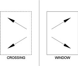
Before we talk about the accuracy tools available to you, we need to briefly cover a more advanced type of selection method called Window/Crossing. You may have already seen this by accident: When you click randomly on the screen without selecting any objects and drag your mouse to the right or left, a rectangular shape forms. It is either dashed or solid (depending on settings, these shapes may have a green or blue fill) and goes away once you click the mouse button again or press Esc. This happens to be a powerful selection tool.
![]() Crossing. A crossing appears when you click and drag to the left of an imaginary vertical line (up or down) and is a dashed rectangle. Any object it touches is selected.
Crossing. A crossing appears when you click and drag to the left of an imaginary vertical line (up or down) and is a dashed rectangle. Any object it touches is selected.
![]() Window. A window appears when you click and drag to the right of an imaginary vertical line (up or down) and is a solid rectangle. Any object falling completely inside it is selected.
Window. A window appears when you click and drag to the right of an imaginary vertical line (up or down) and is a solid rectangle. Any object falling completely inside it is selected.
Figure 1.31 shows what both the Crossing and the Window look like. Practice selecting objects in conjunction with the erase command. Draw several random objects and start up the erase command. Then, instead of picking each one individually (or doing Erase, All), select them with either the Crossing or Window and make a note of how each functions. This is a very important and useful selection method.
1.8 Drawing Accuracy—Part 1
Ortho (F8)
So far, when you created lines, they were not perfectly straight. Rather, you may have lined them up by eye. This of course is not accurate enough for most designs, so we need a better method. Ortho (which stands for orthographic) is a new concept we now introduce that allows you to draw perfectly straight vertical or horizontal lines. It is not so much a command as a condition you impose on your lines prior to starting to draw them. To turn on the Ortho feature just press the F8 key at the top of your keyboard or click to depress the ORTHO button at the bottom of the screen. Then, begin drawing lines. You see your mouse cursor constrained to only vertical and horizontal motion. Ortho is usually not something you just set and forget about, as your design may call for a varied mix of straight and angled lines, so do not be shy about turning the feature on and off as often as necessary, sometimes right in the middle of drawing a line.
1.9 Drawing Accuracy—Part 2
OSNAPs
While drawing straight lines, we generally like those lines to connect to each other in a very precise way. So far we have been eyeballing their position relative to each other, but that is not accurate and is more reminiscent of sketching, not serious drafting. Lines (or for that matter all fundamental objects in AutoCAD) connect to each other in very distinct and specific locations (two lines are joined end to end, for example). Let us develop these points for a collection of objects.
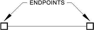
Endpoint
ENDpoints are the two locations at the ends of any line. Another object can be precisely attached to an endpoint. The symbol for it is a square, as illustrated in Figure 1.32.
Midpoint
MIDpoint is the middle of any line. Another object can be precisely attached to a midpoint. The symbol for it is a triangle, as illustrated in Figure 1.33.

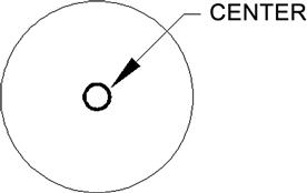
Center
CENter is the center of any circle. Another object can be precisely attached to a center point. The symbol for it is a circle, as illustrated in Figure 1.34.
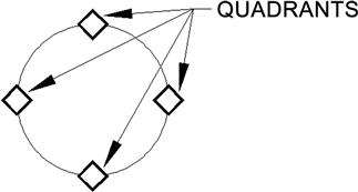
Quadrant
QUADrants are the four points at the North (90°), West (180°), South (270°), and East (0°, 360°) quadrants of any circle. Another object can be precisely attached to a quadrant point. The symbol for it is a diamond, as illustrated in Figure 1.35.
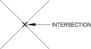
Intersection
INTersection is a point that is located at the intersection of any two objects. You may begin a line or attach any object to that point. The symbol for it is an X, as illustrated in Figure 1.36.
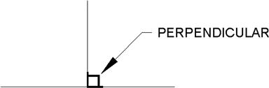
Perpendicular
PERPendicular is an OSNAP point that allows you to begin or end a line perpendicular to another line. The symbol for it is the standard mathematical symbol for a perpendicular (90°) angle, as illustrated in Figure 1.37.
These are the six fundamental OSNAP points we mention for now. There are others of course, such as Node, Extension, Insertion, Tangent, Nearest, Apparent Intersection, and Parallel, but those are used far less often; and with the exception of Tangent, Nearest, and Node (covered in upcoming chapters), they are not discussed.
So how do you use the OSNAPs that we have developed so far? There are two methods. The first is to type in the OSNAP point as you need it (only the capitalized part needs to be typed in: END, MID, etc.). For example, draw a line. Then, begin drawing another line, but before clicking to place it, type in end and press Enter. AutoCAD adds the word of, at which point you need to move the cursor to roughly the end of the first line. The snap marker for endpoint (a square) appears, along with a tool tip stating what it is. Click to place the line; now your new line is precisely attached to the first line.
In the same manner, try out all the other snap points mentioned (draw a few circles to practice Quad and Center). In all cases, begin by typing line, then one of the snap points, followed by Enter. Next, bring the mouse cursor to the approximate location of that point and click.
1.10 Osnap Drafting Settings
As you may imagine, there is a faster way to use OSNAP. The idea is to have these settings always running in the background, so you need not type them in anymore. To set them up, you need to type in osnap or select Tools→Drafting Settings… from the cascading drop-down menu. The OSNAP dialog box appears (Figure 1.38). First, make sure the Object Snap tab is selected, then select the Clear All button. Finally, check off the six settings mentioned previously (Endpoint, Midpoint, Center, Quadrant, Intersection, Perpendicular), and press OK.
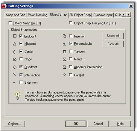
So now you have set the appropriate settings, but you still need to turn them on. For that, we need to mention another F key. If you press F3 or press the OSNAP toggle button at the bottom of the screen, the OSNAP settings become active. Go ahead and do this, then begin the same line drawing exercise; see how much easier it is now as the snap settings appear on their own. This is the preferred way to draw, with them running in the background. Feel free to press F3 anytime you do not need them anymore; OSNAP is also not something that you may want all the time. Figure 1.38 shows the Drafting Settings dialog box, with the discussed OSNAP points checked.
Summary
You should understand and know how to use the following concepts and commands before moving on to Chapter 2:
Additionally, you should understand and know how to use the following tips introduced in this chapter:
Exercises
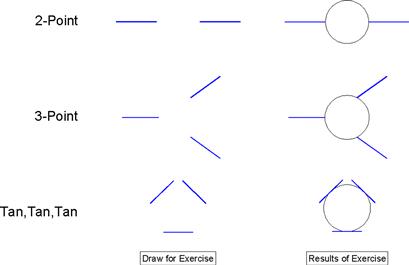
1. Draw the following sets of lines on the left and practice the 2-Point, 3-Point, and Tan, Tan, Tan circle options. You may use the Ribbon, cascading menus, or typing. In all cases, use OSNAPs to connect the circle precisely to the drawn lines. The result you should get is shown on the right. (Difficulty level: Easy; Time to completion:<5 minutes.)
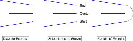
2. Draw an arc using the Start, Center, End option (a commonly used one) as follows. First, draw the three lines shown on the left, making use of the mirror command as needed, then draw the arc itself. Be sure to select from the bottom up, as shown, and use OSNAPs. The result you should get is shown on the right. Try the same exercise by picking from the top down, noticing the difference. (Difficulty level: Easy; Time to completion:<5 minutes.)
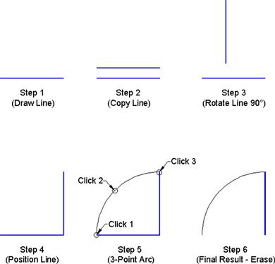
3. Draw a simple door using the 3-Point arc method. This requires some precise mouse clicking and we introduce an alternate method in Chapter 3, but for now this is a good exercise to try. First draw, copy, rotate, and position the lines as seen in Steps 1 through 4, then add the arc as shown in Step 5 (use Ortho and OSNAPs throughout). You may have to try it a few times to get it to look right. Finally, erase the bottom line to complete the door as seen in Step 6. (Difficulty level: Easy; Time to completion:<5 minutes.)
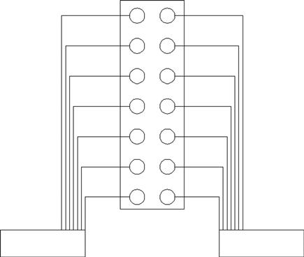
4. Draw the following sets of arbitrary electrical connection shapes. You need only the basic Create and Modify commands, including rectangle, circle, line, offset, fillet, and mirror, as well as OSNAPs and Ortho. Specific sizes are not important at this point, but make your drawing look similar, and use accuracy in connecting all the pieces. (Difficulty level: Easy; Time to completion:<10 minutes.)
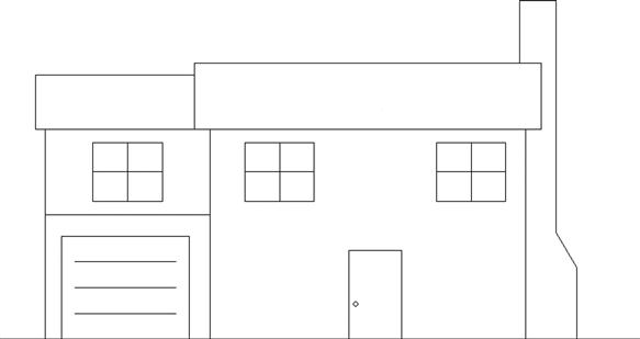
5. Draw the following house elevation using what you learned. You need only the basic Create and Modify commands. The overall sizing can be approximated; however, use Ortho (no crooked lines) and make sure all lines connect using OSNAPs. (Difficulty level: Intermediate; Time to completion:<15 minutes.)
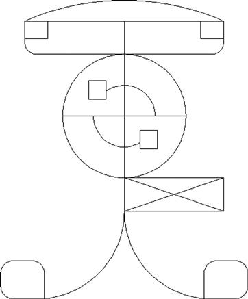
6. Draw the following sets of random shapes. You need only the basic Create and Modify commands, but you use almost every one of them, including multiple cutting edges trim. The overall sizing is completely arbitrary, and your design may not look exactly like this one, but be sure to draw all the elements you see here and use OSNAP precision throughout. (Difficulty level: Intermediate; Time to completion:<15 minutes.)
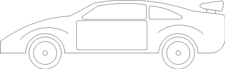
7. Draw the following side view of a car using what you learned. You need only the basic Create and Modify commands. The overall sizing (including multiple fillets needed on most corners) can be approximated; however, use accuracy and make sure all lines connect using OSNAPs. (Difficulty level: Intermediate; Time to completion:<20 minutes.)
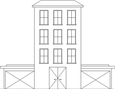
8. Draw the following elevation of a building using what you learned. You need only the basic Create and Modify commands. The overall sizing (windows, door, etc.) can be approximated; however, use accuracy and make sure all lines connect using OSNAPs. There is extensive use of mirroring to save time. (Difficulty level: Intermediate; Time to completion:<20 minutes.)
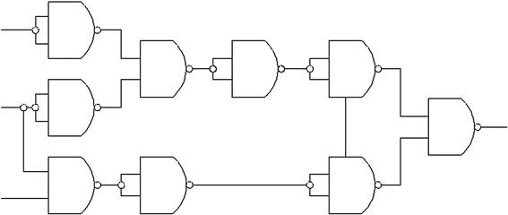
9. Logic diagrams are a familiar sight in electrical engineering; they are made up of components such as AND, OR, Not OR (NOR), Not AND (NAND), and others, as well as various inputs and outputs (I/O). They are used to construct signal flow diagrams by representing voltage flows as True (+V) and False (0V). Truth tables (you may have seen them in junior high math classes) are derived from logic diagrams. These schematics lend themselves easily to AutoCAD. Draw the following diagram using basic Create/Modify tools. Extensive use is made of the copy command. (Difficulty level: Intermediate; Time to completion:<20 minutes.)
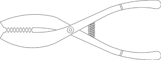
10. Draw the following set of pliers using just basic Draw/Modify commands. Extensive use is made of the copy and mirror commands, along with trim. The rest is just lines, arcs, and a few circles. (Difficulty level: Intermediate; Time to completion:<20 minutes.)