AutoCAD Fundamentals
Part II
Learning Objectives
You learned a great deal in the first chapter, in fact the majority of what you need to know to get started on a design. This chapter serves as a “clean up” and concludes the basic introduction to AutoCAD, as there are just a few more topics to get to. Here, we discuss the following:
By the end of the chapter, you will have learned all the necessary basics to begin drafting your first project, including setting proper units, analyzing what you have done, and saving your work. After an introduction to layers in Chapter 3, you will begin a realistic architectural design.
Estimated time for completion of chapter: 2 hours.
2.1 Grips
We begin Chapter 2 with grips, a natural progression from learning the OSNAP points. These are relatively advanced editing tools, but chances are you have already made them appear by accident by clicking an object without selecting a command first. That is OK; just press Esc and they go away. But, what are these mysterious blue squares? Take a close look; after learning OSNAPs, these should look familiar.
Grips are control points, locations on objects where you can modify that object’s size, shape, or location. They are quite similar to the “handles” that you find in Photoshop® or Illustrator® if you are familiar with those applications.
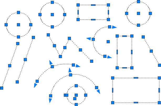
To try out the concept, first draw some lines, arcs, circles, and rectangles. Then, activate grips by clicking on any of the shapes (as seen in Figure 2.1). The objects become dashed and the grips appear. When your mouse hovers over one of them, the grip turns pink. If you click on it, it becomes red, meaning it is active (or hot). With the grip activated, move the mouse around. The object changes in one of several ways. A line or circle can be moved around if the center grip is selected. A circle can be scaled up or down in size if the outer quadrants are selected. Arcs can be made larger or their length increased. Other grips, such as the endpoints of a line or corners of a rectangle, change (or stretch) the shape of that object if activated and moved. Try them all out.
There is of course much more to grips. Formally referred to as multifunctional grips, they perform other construction tasks via an available vertex menu that appears if you hold your mouse over them. We explore this in depth in a later chapter.
2.2 Units and Scale
We have not yet talked about any drawing units, such as feet, inches, or centimeters. When you practiced the offset command, you entered a value, such as 2 or 3, but what did it mean? Well, as you inadvertently discovered, the default unit system in AutoCAD, until you change it, is a simple decimal system of the type we use in everyday life. However, it is unitless, meaning that the 2 or 3 you entered could have been anything—feet, inches, yards, meters, miles, or millimeters. Think about it: It is an easy and powerful idea, but it is up to you to set the frame of reference and stick to it. So, if you are designing a city and 1 is equal to a mile, then 2 is two miles and 0.5 is half a mile. AutoCAD does not care; it gives you a system and lets you adapt it to any situation or design. Then, you just draw in real-life units or, as we say in CAD, 1-to-1 units. This is the Golden Rule of AutoCAD. Always draw everything to real-life size. Do not scale objects up or down.
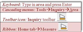
A decimal system of units is OK for many engineering applications, but what about architecture? Architects prefer their distances broken down to feet and inches, because it is always easier to understand and visualize a distance of 22’-6" than 270". To switch to architectural units, type in units and press Enter, or select Format→Units… from the cascading menus, and the dialog box in Figure 2.2 appears.
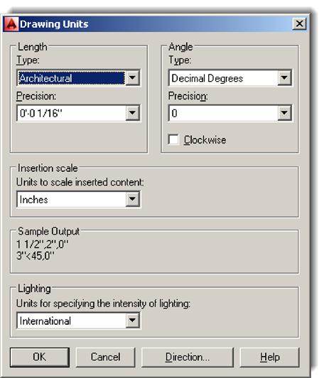
Simply select Architectural from the drop-down menu at the upper left and ignore the rest of the options in the dialog box; there is no need to change anything else at this point. Now, as you draw and enter in units, they are recognized as feet or inches. To enter in 5 feet (such as when using the offset command), type 5’. To enter in 5 inches, there is no need for an inch sign, just type in the number 5; AutoCAD understands. To mix feet and inches, type in 5’6, which is of course 5’-6"; there is no need for a hyphen either.
2.3 Snap and Grid
These two concepts go hand in hand. The idea here is to set up a framework pattern on the screen that restricts the movement of the crosshairs to predetermined intervals. That way, drawing simple shapes is easy because you know that each jump of the mouse on the screen is equal to some preset unit. Snap is the feature that sets that interval, but you need the grid to make it visible. One without the other does not make sense, and usually they are set equal to each other. Snap and Grid are not used that often in the industry, but it is a great learning tool, and we do a drawing at the end of this chapter using them. It also helps knowing about this feature, as it can be inadvertently activated by pressing the Snap or Grid buttons at the bottom of the screen. Lately, having a Grid on has also been the default setting in AutoCAD.
To Set Snap
Type in snap.
To Set Grid
Type in grid.
![]() AutoCAD says: Specify grid spacing(X) or [ON/OFF/Snap/Major/aDaptive/ Limits/Follow/Aspect]<0’−0½">:
AutoCAD says: Specify grid spacing(X) or [ON/OFF/Snap/Major/aDaptive/ Limits/Follow/Aspect]<0’−0½">:
Type in 1, setting the grid to 1 inch.
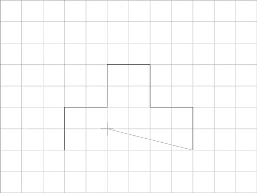
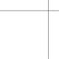
Snap and Grid are now set, although you may have to zoom to extents (Tip 3) to see everything. In previous versions of AutoCAD, the grid was hard-to-see dots. In AutoCAD 2012 and continuing with 2014, it became reminiscent of graph paper, as seen in Figure 2.3. Try drawing a line; you notice right away that the cursor “jumps” according to the intervals you set. F9 turns Snap on and off, while F7 takes care of Grid, and you can always toggle back and forth using the drawing aids buttons at the bottom of the screen. Figure 2.3 is a screen shot of Snap and Grid in use while drawing a simple shape. You can, if desired, change the color of the grid’s major and minor lines via the right-click Options…, Display tab, Colors… button. The entire Options dialog box is described later in the text, but you should explore this on your own as well.
2.4 Cartesian Coordinate System
AutoCAD, and really all CAD programs, rely on the concepts of axes and planes to orient their drawings or models in space. In 2D drafting, you are always drawing somewhere on AutoCAD’s X-Y plane, which is made up of the intersections of the X and Y axes. When you switch to 3D, the Z axis is made visible to allow drawing into the third dimension. The X, Y, and Z axes are part of the Cartesian coordinate system, and we need to briefly review this bit of basic math and illustrate why it is helpful to know it. Figure 2.4 illustrates the 2D coordinate system, made up of the X and Y axes and numbered as shown.
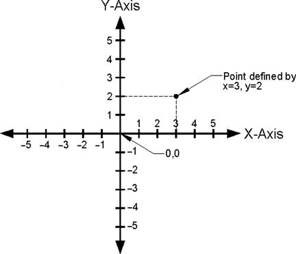
This system is important not only because you may want to know where in space your drawing is but so you can create objects of a given size by entering their X and Y values. Moreover, we refer to this system often for a variety of other construction needs and distance entries, including inserting drawings into the point 0,0, so review and familiarize yourself with it again, as it is likely you may not have seen this in a while. Next, we introduce the various distance entry tools. As you go through Section 2.5, knowing the Cartesian coordinate system helps you understand what is going on.
2.5 Geometric Data Entry
The ability to accept sizing information when creating basic objects is the “bread and butter” of any drafting or modeling software. Geometric data entry refers to the various techniques needed to convey to AutoCAD your design intent, which may involve everything from the length and angle of a line to the diameter of a circle, or the size of a rectangle.
AutoCAD has two precise methods to enter distances, angles, and anything else you may need. These techniques are the older “manual” method, where you enter data via the keyboard and it appears on your command line, and the newer “dynamic” method, where you still use the keyboard, but the data appears on your screen via what is known as a heads-up display. Most students probably gravitate toward the newer method, and indeed it offers many advantages, not the least of which is faster data input. We consider this the primary method in this text but present the manual method as an optional alternative. Experience has shown that some students dislike the additional on-screen clutter that Dynamic Input adds, finding the manual method less distracting. Ultimately, it is up to you to decide what to use.
Dynamic Input
Erase anything that may be on your screen and turn off all drawing aids at the bottom of the screen, including Snap, Grid, and anything else you may have on. Now press the DYN drawing aid, as seen in Figure 2.5.
This type of input allows you to specify distances and angles directly on the screen. Begin drawing a line and you see an example of Dynamic Input in action. An arbitrary example is shown in Figure 2.6. Your values of course may be different, but the basic display should be the same.
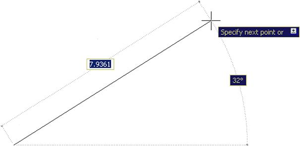
Notice what AutoCAD is allowing you to do. The 7.9361 value in Figure 2.6 is surrounded by a box, meaning it is editable. All you have to do is enter a desired value, so enter a small value, such as 5, but do not press Enter yet. What if you wanted to change the angle of the line? Simply press the Tab key, tab over to the 32° value, and enter something else, perhaps a 45. Finally, press Enter. Your line 5 units long at 45° is done. The line command continues of course, and you can repeat this as much as needed.
This works with Ortho on as well. In that case, you enter only distance values, no angles, as Ortho forces the lines to all be 90°. Be sure to “lead” the mouse (and in turn the lines being created) by slightly moving the mouse in the direction you want to go.
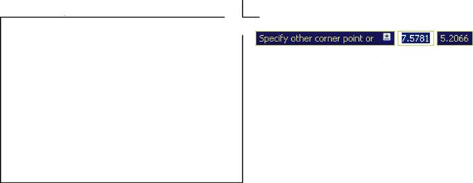
To use Dynamic Input to draw a rectangle (5"×3" in this example), make sure DYN is on, begin the command, and click anywhere to start the rectangle. You see fields in which to enter the values for the height and width (Figure 2.7). As before, enter a new value in the first text field (5) and Tab over to the next field, entering the other value (3). As you press Enter, the 5"×3" rectangle is created. Note of course that the first value is the width and the second value is the height.
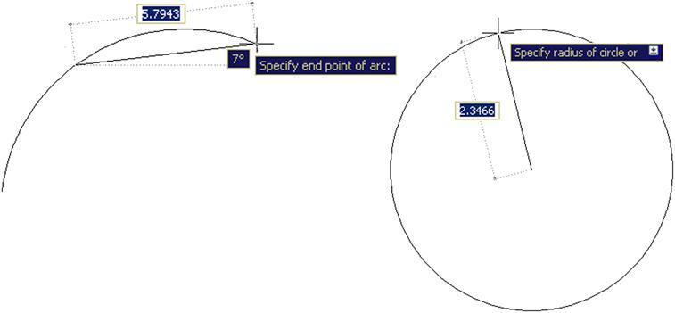
The usefulness of Dynamic Input extends out to just about any shape with which you may work. Figure 2.8 shows DYN with an arc (left) and a circle (right). As before, you can specify on-screen data needed to create that particular shape.
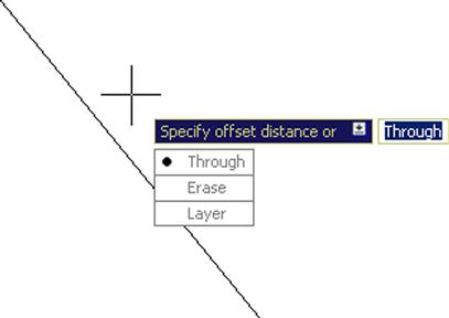
You may notice also that some of the “heads-up” menus show a downward pointing arrow. You can use the down arrow on your keyboard to drop down the menu and reveal other choices, which of course mimic what is available in the parentheses on the command line. Figure 2.9 is one example with the offset command. You can cycle through these options to select what you need.
Manual Input
Using the manual method, you can do the same thing that can be done with the DYN input. Let us run through a few scenarios and, along the way, introduce Direct and Relative Data Entry. The simplest case just involves lines. Turn off the DYN button and begin the line command, clicking where you want to start. Now, all you have to do is point the mouse in the direction you want the line to go (moving the mouse a bit in that direction), enter a length value on the keyboard, and the line appears. You can continue this “stitching” indefinitely. Note that we have not yet explored how to draw the lines at various precise angles, except for 90°; for that, just turn on Ortho. If using Ortho, be sure to once again “lead” the linework as before, by moving your mouse in the direction you want to go, so AutoCAD understands your intent.
Whether done manually or via DYN, this point-by-point stitching, called Direct Data Entry, is a useful technique. One example of its use occurs after you do a basic room or building perimeter survey. This may just be a wall-by-wall sequential field measurement of a space. When you return to the office you can quickly enter the wall lengths into AutoCAD one at a time via this technique. Do take a few minutes to practice it.
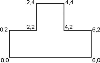
Direct Distance Entry can be done manually one other way. While not a common technique for day-to-day drafting, it really gets you to practice and understand the Cartesian coordinate system. What you do is enter data one click at a time by following the coordinate points. To practice this, begin the line command, then, instead of clicking anymore, type in the following values, pressing Enter after each one:
These are the X and Y values sfor the lines to follow; and if you typed correctly, then the shape seen in Figure 2.10 should emerge on your screen one segment at a time.
A variation on Direct Data Entry is called Relative Data Entry. This is useful for quickly and easily creating shapes, such as rectangles, anywhere on the screen. It also allows you to enter in various angles for lines besides the Ortho-induced 90°. To do either you need to know two new symbols, @ and<.
The @ symbol frees you from 0,0 and can be interpreted as meaning “relative to.” In the case of a rectangle, this means you can create it relative to wherever you are in space by simply starting the rectangle command and specifying an X and a Y value preceded by the @ symbol. So, for a 5"×3" rectangle,
The rectangle then appears.
Now that you know about the @ symbol and what it does, you can also draw lines at any angle by also employing the additional<symbol. Any numerical value after this “alligator tooth” symbol is interpreted as an angle. The format is as follows: @Distance<Angle. Therefore, to create a line that is 10 units long at 45°,
The line (10 units long, at 45°) appears.
As we conclude Section 2.5, remember that, when it comes to creating a rectangle, the dynamic and basic manual methods are not the only ones available. A brief mention was made in Chapter 1, when the rectangle was first introduced, that you can also access length and width data as part of the command line suboptions, such as pressing d for Dimensions. You can vary that by specifying a total area then either the length or width. It may be worth it to briefly review all this again to have the full set of options available to you. You need to create quite a few rectangles as you begin drafting. They are the basis of furniture, mechanical components, and even entire floor plans, as we soon see. You should be well versed in all the ways to create them.
2.6 Inquiry Commands
Our next topic in AutoCAD fundamentals is the Inquiry commands set. These commands are there to give you information about the objects in front of you on the screen as well as other vital data like angles, distances, and areas. As such, it is important for you to learn them early on; the information these commands provide is especially valuable to a beginner student and will continue to be essential as you get more experienced. Inquiry commands were upgraded just a few releases ago and they currently comprise:
![]() Area gives you the area of an object or any enclosed space.
Area gives you the area of an object or any enclosed space.
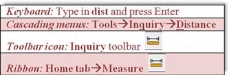
![]() Distance gives you the distance between any two points.
Distance gives you the distance between any two points.
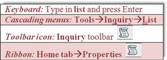
![]() List gives you essential information on any object or entity.
List gives you essential information on any object or entity.
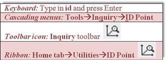
![]() ID gives you the coordinates of a point.
ID gives you the coordinates of a point.
![]() Radius gives you the radius of a circle or arc.
Radius gives you the radius of a circle or arc.
![]() Angle gives you the angle between two lines.
Angle gives you the angle between two lines.
![]() Volume gives you the volume of a 3D object.
Volume gives you the volume of a 3D object.
![]() Mass Properties lists various mass properties of a 3D solid.
Mass Properties lists various mass properties of a 3D solid.
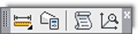
We cover the first four inquiry commands in detail (area, distance, list, and ID) and include a brief mention of radius and angle. Volume and mass properties are not discussed here, as those are for 3D work. As before, all commands can be accessed through the usual four ways: typing, cascading menus, toolbars, and the Ribbon. The toolbar used is the Inquiry toolbar, as seen in Figure 2.11, and should be brought up on screen using the methods described in Chapter 1.
Area
Area is a very important and useful Inquiry command. It is used often by architects to verify the area of a room or an entire floor plan. Area calculations are performed in two ways: either on an object or, more commonly, point by point (such as the area of a room). Draw a rectangle of any size. We go over both methods, although with a rectangle you would really use only the object method, saving the point-by-point approach for a more complex floor plan.
Point By Point
This is used when measuring an area defined by individual lines (not an object).
Step 1. Make sure your units are set to Architectural and you have a rectangle on your screen.
Step 2. Begin the area command via any of the preceding methods.
![]() AutoCAD says: Specify first corner point or [Object/Add area/Subtract area]<Object>:
AutoCAD says: Specify first corner point or [Object/Add area/Subtract area]<Object>:
Step 3. Activate your OSNAPs (F3) and click your way around the corners of the rectangle until the green shading covers the entire area to be measured (five clicks total).
Specify next point or [Arc/Length/Undo]:
Specify next point or [Arc/Length/Undo]:
Specify next point or [Arc/Length/Undo/Total]<Total>:
Specify next point or [Arc/Length/Undo/Total]<Total>:
Step 4. When done, press Enter. You get a total for area and perimeter. Mine said:
Yours of course will likely say something different.
Object
This is used when you have an object (not an area defined by individual lines) to measure.
Distance
The distance command gets you the distance between any two points. Although we practice on the corners of a rectangle, the command works on any two points, as selected by a mouse click, even an empty space.
Step 1. Make sure your units are set to Architectural, a rectangle is on your screen, and your OSNAPs are activated.
Step 2. Begin the distance command via any of the preceding methods. (Be sure to read the note after Step 4.)
![]() AutoCAD says: Specify first point:
AutoCAD says: Specify first point:
Step 3. Select a corner of the rectangle.
![]() AutoCAD says: Specify second point or [Multiple points]:
AutoCAD says: Specify second point or [Multiple points]:
Step 4. Select the other corner across the rectangle. AutoCAD then gives you some information. Mine said:
Distance=13.5521, Angle in XY Plane=0, Angle from XY Plane=0
Yours will say something different.
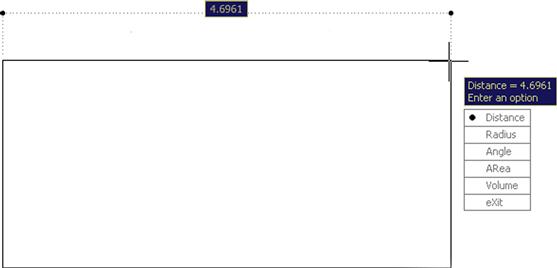
Note: There is an important difference in procedures if you use the icons or the Ribbon. In those cases, DYN activates and you get a graphical representation of the distance, as seen in Figure 2.12. If you type or use cascading menus, then you get the command line results seen in Steps 1 through 4.
List
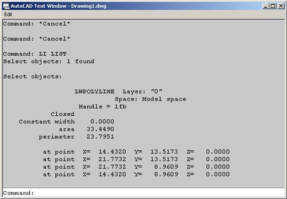
The list command gives you information about not just the geometric properties of the object but also its CAD properties, such as what layer it is on, the subject of the next chapter. It is an extremely useful command that clues you in on what you are looking at (whether a beginner or an expert, you will sometimes ask yourself this question).
Step 1. Make sure you have something on your screen to investigate. Draw a line, rectangle, or circle.
Step 2. Begin the list command via any of the preceding methods.
Step 3. Select your object (it becomes dashed) and press Enter. The command line in the form of a text window appears mid-screen. Look it over and close it (X, upper right, or just press F2) when done. What mine said about an arbitrary rectangle is shown in Figure 2.13.
ID
This command is the simplest of all. It tells you the coordinates of a point in space, such as the intersection of two lines. This is useful for inserting blocks (Chapter 7) and just plain old figuring out the general location of an object, something that may be needed for Xrefs (Chapter 17).
Step 1. Make sure you have something on your screen to ID. Create a line or a rectangle.
Step 2. Begin the ID command via any of the preceding methods.
Step 3. Using OSNAPs, select a point, such as the corner of a rectangle or end of a line. AutoCAD gives you the X, Y, and Z coordinates. Here is what I got; you of course will likely get different values:
Radius and Angle
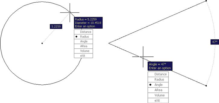
You should now have a good feel for the Inquiry toolset, so go ahead and practice the remaining two commands on your own. Radius and angle cannot be typed in; you must use the toolbars, the cascading menus, or the Ribbon.
To practice Radius, draw an arbitrary circle, then activate the command and select it. A radius is displayed and you can just press Esc to get out. The result is shown in Figure 2.14 (left). To get an angle reading create two “alligator teeth” lines, activate the command, and select both lines. The angle is displayed, and again, you can press Esc to exit. The result is shown in Figure 2.14 (right). Note that these commands are “dynamic” in nature, so DYN activates when you use them.
This concludes the section on Inquiry commands. We are now in the home stretch and will explore some commands and concepts that do not quite fit in neatly anywhere else but will prove to be very useful as you start a realistic project in the next chapter and, of course, everyday AutoCAD use.
2.7 Additional Drafting Commands
We are going to take a moment to explore four additional drafting commands: explode, polygon, ellipse, and chamfer. They are not mentioned in Chapter 1, because they are not part of the essential set of drafting commands. The need for lines and rectangles in a typical drawing is far greater than the need for ellipses or polygons. However, in the few cases you do need one of those shapes, there really is no substitute. We start off with the unusual explode command.
Explode
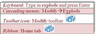
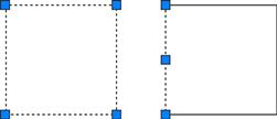
Explode is used to make complex objects simpler. That means a rectangle becomes four separate lines, and other objects we have yet to study (blocks, text, dimensions, hatch, etc.) are simplified into their respective components. This command is mentioned in almost every chapter, as virtually all AutoCAD entities can be exploded—although many should never be! To try it out, we again need a rectangle of any size. Make sure you are using the actual rectangle command, not just four connected lines. Those are already in their simplest form, and explode does not work on them.
Step 1. Begin the explode command via any of the preceding methods.
Click any of its lines and you notice that each line is independent, as seen in Figure 2.15. Keep in mind that you cannot explode circles, arcs, and lines (previously mentioned), as those are already the simplest objects possible. There is a way to reverse explode, in addition to an immediate undo. It is called a pedit command (discussed in Chapter 11), but that applies only to simple compound objects, such as a rectangle. If you explode a hatch pattern and save your work, that is it, no going back. This is why you see appropriate warnings when we get to those chapters.
Polygon
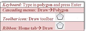
The polygon command is a useful tool that we need in later chapters for a project. A polygon, strictly speaking, is any shape with three or more sides to it. Of course, in those cases when it has three sides (triangle), you can draw it with existing line techniques. Same thing with four sides (square or rectangle). However, what about five sides or more, such as a pentagon or hexagon? Here, a polygon command is needed, as it is a real chore to draw these shapes using the line command—just try figuring out all the correct angles.
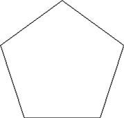
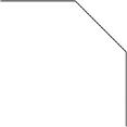
Drawing polygons, however, presents a complication you do not have with simpler shapes. With a rectangle, you specify the height and width and that is it, but how do you do that with, say, a pentagon? Figure 2.16 is a picture of one. What is the height? What is the width? It is not an easily measured shape.
The solution that drafters came up with a long time ago (many of AutoCAD’s techniques are just adaptations of pencil and paper board-drafting methods used for decades) is to enclose the shape in a circle of a known radius or diameter. Of course, you can also enclose the circle inside the polygon.
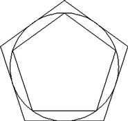
With either approach, it is much easier to specify a size. You just say, “I need a pentagon that fits inside (or outside) a circle of 10 inches in diameter.” This is where the terms inscribed and circumscribed come from. Figure 2.17 is a diagram of two pentagons, one inscribed in a circle and one circumscribed about a circle. Note the tangencies. In one case, the points of the polygon touch the circle; in the other case, its sides touch it.
Let us go through the steps in making a polygon inscribed in a circle. Begin by drawing a circle with an arbitrary radius of 5. Note that we do not need this step to create a polygon, but for your first try, it is a great help in visualizing what you are doing. Then proceed as shown next.
Step 1. Begin the polygon command via any of the preceding methods.
![]() AutoCAD says: Enter number of sides<4>:
AutoCAD says: Enter number of sides<4>:
Step 2. Enter the number 5 for five sides (making it a pentagon), and press Enter.
![]() AutoCAD says: Specify center of polygon or [Edge]:
AutoCAD says: Specify center of polygon or [Edge]:
Step 3. With your OSNAPs on, click to select the center of the circle.
![]() AutoCAD says: Enter an option [Inscribed in circle/Circumscribed about circle]<I>:
AutoCAD says: Enter an option [Inscribed in circle/Circumscribed about circle]<I>:
Step 4. Now that you know what these terms mean, go ahead and press Enter to select i for “Inscribed in circle” (the default value). You can just as easily select c as well.
![]() AutoCAD says: Specify radius of circle:
AutoCAD says: Specify radius of circle:
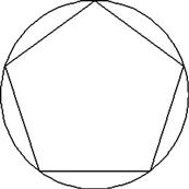
Step 5. Enter the value 5. A screen shot of the result is in Figure 2.18.
You can now erase the circle, since it was just a guide. In the future you do not need it; just click to place the polygon anywhere on the screen. Go ahead and practice this command, but this time select a different number of sides (six or more) and also use the Circumscribed option. This new command leads us into the first challenge exercise.
 Drawing Challenge—Star
Try this exercise based on what you learned. Draw a perfect five-sided star, such as the one shown in Figure 2.19. Think about everything we talked about up to this point. Only four commands are needed to create the star. Take a few minutes to try to draw it. If you cannot get it to look right, the answer is at the end of this chapter, just before the summary.

Ellipse
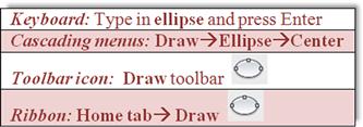
The ellipse command is easy to use and is needed when we draw furniture in Chapter 4, so it is included here. The command can be executed in one of two ways: Center or Axis, End. You can also create a partial ellipse by defining just a section of it.
Step 1. Begin the ellipse command via any of the preceding methods.
![]() AutoCAD says: Specify axis endpoint of ellipse or [Arc/Center]:
AutoCAD says: Specify axis endpoint of ellipse or [Arc/Center]:
Step 2. Click anywhere on the screen.
![]() AutoCAD says: Specify other endpoint of axis:
AutoCAD says: Specify other endpoint of axis:
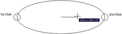
Step 3. With Ortho on (not required but good to have), click again somewhere off to the left or right of the first point. Then, move the mouse back toward the center as the ellipse is formed, as seen in Figure 2.20.
![]() AutoCAD says: Specify distance to other axis or [Rotation]:
AutoCAD says: Specify distance to other axis or [Rotation]:
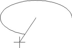
Step 4. Click anywhere again to complete the ellipse. You can also specify a rotation angle along the major axis (the line between clicks 1 and 2). This would be as if the ellipse were rotating away (or toward) you. For a variation on this, try the Arc submenu of the ellipse, which is essentially similar in execution until the final step, when you trace how much of the ellipse you want to see, as shown in Figure 2.21.
Chamfer
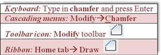
You may have already tried the chamfer command, as it sits right next to fillet in the cascading menus and the Modify toolbar. While normally not used as often as a fillet, it is still very much worth investigating. A chamfer is a beveled edge connecting two surfaces. Think of it as a fillet that is angled instead of round. Chamfers may have a 45° corner, but this is not required; AutoCAD allows for asymmetrical chamfers.
To try out the command, draw two perpendicular lines similar to the fillet exercise in Chapter 1 (reproduced in Figure 2.22) and follow these steps.
Step 1. Begin the chamfer command via any of the preceding methods.
(TRIM mode) Current chamfer Dist1=0.0000, Dist2=0.0000
Select first line or [Undo/Polyline/Distance/Angle/Trim/mEthod/Multiple]:
Step 2. No distance has been entered yet, and any attempt at chamfer results in a chamfer radius of zero. Press d for Distance.
![]() AutoCAD says: Specify first chamfer distance<0.0000>:
AutoCAD says: Specify first chamfer distance<0.0000>:
Step 3. Enter a small value, such as 1.
![]() AutoCAD says: Specify second chamfer distance<1.0000>:
AutoCAD says: Specify second chamfer distance<1.0000>:
Step 4. Here the 1 is not needed again, so just press Enter.
![]() AutoCAD says: Select first line or [Undo/Polyline/Distance/Angle/Trim/mEthod/ Multiple]:
AutoCAD says: Select first line or [Undo/Polyline/Distance/Angle/Trim/mEthod/ Multiple]:
Step 5. Select the first line.
![]() AutoCAD says: Select second line or shift-select to apply corner or [Distance/Angle/Method]:
AutoCAD says: Select second line or shift-select to apply corner or [Distance/Angle/Method]:
Step 6. As you move the mouse toward the second line, you again see a preview of the completed command (similar to fillet). Select the second line and the chamfer is created as seen in Figure 2.23. Zoom in if needed to see it.
If the chamfer fails, it is possible that you selected values too large for the available lines. Another way to create a chamfer is using the length of one line segment together with an angle, using the Angle option. Experiment with both.
Templates
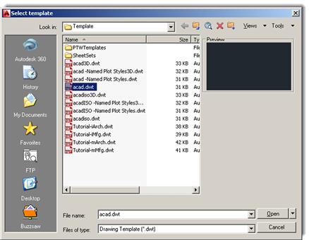
Templates are something of a mystery for a beginner AutoCAD student. What exactly are they? While templates can get complicated in what they contain, they are really just files with some information embedded in them, with all the proper settings but no actual design present. So it is a blank page with some intelligence built in and everything set up and ready for you to draw. These templates can be saved under a .dwt extension, but you really need not concern yourself with this. What is important is being able to open a new file and know what you are looking at. Using the cascading menu File→New…, you default to the screen in Figure 2.24. Open up the highlighted acad.dwt and you have a blank file, and that is it.
Limits
This is yet another topic that causes confusion. Limits are not technically necessary, but many textbooks persist in having you set them up. All they are is an indication of the size to which your drawing area is preset. Remember, however, that it is limitless, so all limits refer to is the area you can work on without a regen. If you draw a shape that is way beyond your limits, you simply regenerate the screen via a Zoom, Extents (see Tip 3 in Chapter 1 for a reminder) and the limits move to just beyond this new shape, so setting them is rather redundant. If you would like to set them anyway, just type in limits, press Enter, and set the lower left corner to 0,0, then the upper right corner to perhaps 100’, 50’, or anything else you wish.
Save
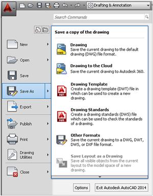
Needless to say, you have to save your work; AutoCAD will eventually lock up or crash. If not, Windows will, there will be a power failure, or you may spill coffee on your laptop, so it is just a good habit to get into. Starting in the next chapter, you need to start saving your work. To do so, you can type in save and press Enter or press the graphic of a disk at the top of the screen. Another way is to drop down the arrow located next to the big red A at the upper left of the screen (Figure 2.25) and choose Save or Save As. You then get the usual Save Drawing As dialog box from which you should know how to proceed.
Help Files
AutoCAD, like pretty much every software application, has extensive Help files and indeed that is one way (though not recommended) to attempt to learn the software. A better application of Help is to explore it once you know how to use AutoCAD and need assistance with a particular aspect of a command. Tool tips that appear with every command can be considered to be part of the Help files.
AutoCAD’s Help files have come a long way in recent releases. The original method to access them was generally to press F1 (same as for other software), and the installed files would come up. Over the years, they became context sensitive and showed only relevant results based on what you were doing. You could also just search for what you wanted and access additional information, including examples. Autodesk even offered a printed Help files manual for those preferring paper.
These files, however, were part of AutoCAD, could not be updated by Autodesk between releases, and offered very little interactive content and access to other tools. All that began to change as internet access became virtually guaranteed as part of working on a computer. The monumental shift with Help files in recent years was to move them completely online and link them with additional tools and functionality. Today, with AutoCAD 2014, online content is accessed if the internet is available, and built-in files are not even offered with AutoCAD (though you can download them). As far as paper help manuals? I am not aware of them being offered anymore.
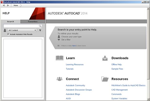
As just mentioned, Help files are now just a part of a larger, interactive suite of online tools, applications, and resources. To access the regular Help files, you can still just press F1. You can do this without any commands active (resulting in Figure 2.26) or in “context-sensitive” mode, while in the middle of a command (such as shown in Figure 2.27 with “line”).
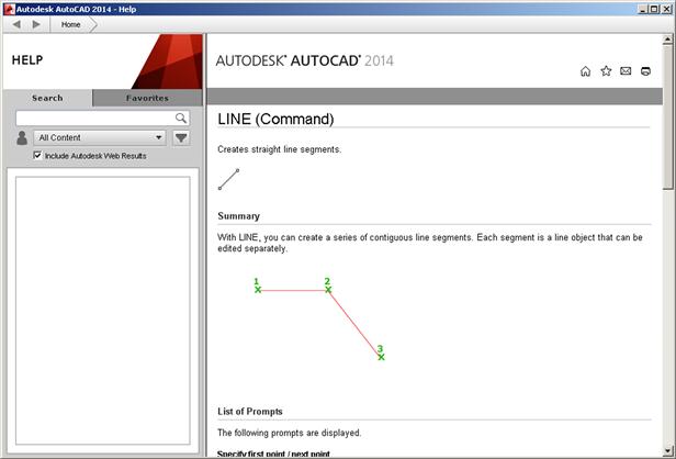
In both modes of the Help files, you can do a search for any other commands and find related tasks, references, and concepts. Note also how, on the left-hand side of the Help files, you can filter what you see based on your level of interest and responsibility. You can now access pretty much anything that has to do with that command, including programming tools, related tutorials, and even relevant blog entries. It is an interesting, if overwhelming, approach and signifies a major shift in Help file philosophy. You are now getting content-based, Googlelike content to cover every angle, not just a cookie-cutter text file to explain the command.
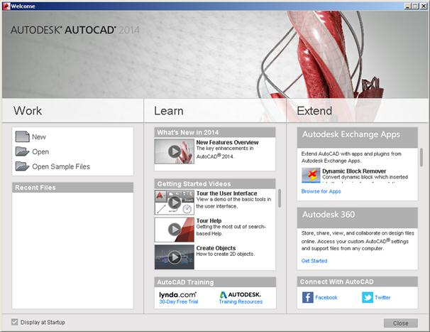
There is more to help files, however, in the form of additional content. Part of it can be accessed through the Help drop-down menu (including the Welcome Screen), and part of it through the AutoCAD Exchange. Take a look at the Help cascading menu. There you will find the Welcome Screen… choice, which will give you the screen you may have already seen when you first fired up AutoCAD (Figure 2.28). The welcome screen gives you broad access to recent files, “what’s new” tutorials, and access to various applications and “connect” methods, meaning blogs, information exchanges, and similar professional and social media tools. Explore a bit on your own.
From the same Help cascading menu, note that you can also download and install the Help files, if you anticipate working off-line a lot and generally want local access to the files. They are not regularly updated or interactive, but do the job for most users. Also note many choices for on-line help for developers and training resources. Somewhat related to this is the Autodesk 360 site, which is basically a “cloud” for data storage and collaboration. While we do not discuss Autodesk 360 further here, it may be a good idea to read up on it on the Autodesk website. Collaborative cloud work is something to watch for in the future, and at the very least you will be familiar with the subject if it comes up in conversation.
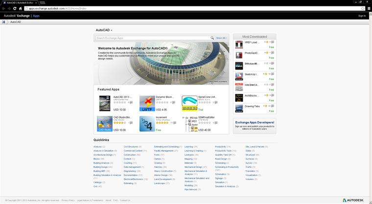
Finally, we have the Autodesk Exchange (Figure 2.29). You can access it at any time via a small X toward the upper right of the screen, to the right of the Autodesk 360 “Sign In.” The Exchange is also geared toward developers and “power users” with various tools and application to customize, extend, or otherwise enhance AutoCAD. Although, as a beginning user, you probably will not need all this additional content (beyond the Help files, that is), make a note of what you see for future reference.
As you can see, a tremendous amount of useful information is found in all these references. You will need to occasionally explore these files for answers, so get comfortable with them at the outset.
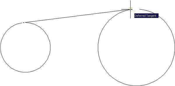
Tangent OSNAP
The Tangent OSNAP point is necessary to draw part of Exercise 6 and is one of three additional OSNAP points mentioned throughout upcoming chapters. Tangent works by allowing you to create a line that maintains perfect tangency to a circle or an arc. Because this OSNAP is used quite rarely, just type in TAN when you need to create the tangency; you see the symbol shown in Figure 2.30. Once started, create another tangency point on another circle or arc.
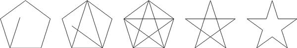
Drawing the Star
As promised, the technique of drawing the star is as follows. First, create a pentagon. Then, noticing that it is a five-point geometric shape, draw lines from endpoint to endpoint, connecting those vertices. Finally, erase the pentagon and use trim to erase the inner lines, as shown in the progression in Figure 2.31.
The reason students do this simple exercise is to underscore a very important point. AutoCAD is used across a vast array of industries, each with its own symbols and unique objects. It would be impossible for the software to include all of them in its database. Instead, AutoCAD gives you basic tools and leaves it up to your creativity and skill to create the shape you need. So, when at a loss as to how to draw something you imagined in your mind, stop and think about the basics that you learned and how you can put them together into something new.
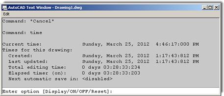
Time
This interesting command allows you to keep track of various time factors involved with a drawing, such as when it was created, last updated, or the total time spent on it. This could be useful for billing purposes when doing contract drafting or good when you are the boss and want to see how long an employee actually spent on a file. For those students just starting out, or if you are not anyone’s boss yet, keep this command in mind, someone may be watching you! To use it with a drawing open, just type in time and press Enter. You will see the text window in Figure 2.32. Yours, of course will likely say something different.
Review everything presented so far. In Chapter 3, we introduce the layers concept and put all the preceding together to begin drawing a floor plan. Remember that learning AutoCAD is cumulative, and you need everything we have covered so far, no more and no less, to successfully deal with the upcoming material, so make sure you understand it all before moving on.
Summary
You should understand and know how to use the following concepts and commands before moving on to Chapter 3:
![]() Activating them, using Esc to get out
Activating them, using Esc to get out
![]() Architectural and Engineering (Decimal) units
Architectural and Engineering (Decimal) units
![]() Setting both, turning them on and off
Setting both, turning them on and off
![]() Understanding the Cartesian coordinate system
Understanding the Cartesian coordinate system
Exercises
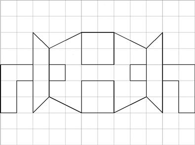
1. Open a new file, set units to Architectural, and set both your snap and grid to 1". Then, draw the following shape. Keep in mind the spacing between each dot is now 1". You would be wise to use the mirror command to complete this faster. The linework in this example has been darkened slightly for clarity. (Difficulty level: Easy; Time to completion:<5 minutes.)
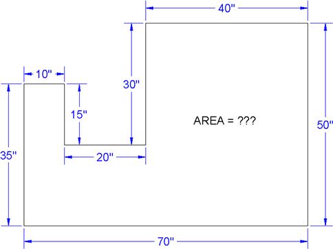
2. Open a new file and set units to Architectural. Then, draw the following figure using the DYN drawing aid. When done, use the area command to find its area. Redraw the shape again via the manual method. (Difficulty level: Easy; Time to completion:<5 minutes.)
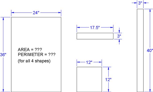
3. Open a new file and set units to Architectural. Draw the following shapes using the manual Relative Distance Entry (the @ sign) method. Repeat the exercise using the DYN method. Repeat again using the rectangle command’s length and width suboptions. Finally, use the area command (Object option) to find the area and perimeter of each shape. The sizes are 24"×36", 17.5"×3", 12"×12", and 3"×40". Remember that the first number is always the X; the second is the Y, as shown in the exercise figure. (Difficulty level: Easy; Time to completion:<10 minutes.)
4. Open a new file and set units to Architectural. Draw the following figure using the basic circle, line, offset, trim, and fillet commands. Create the top view first, using circles and project lines for the side view. (Difficulty level: Easy; Time to completion: 5–7 minutes.)
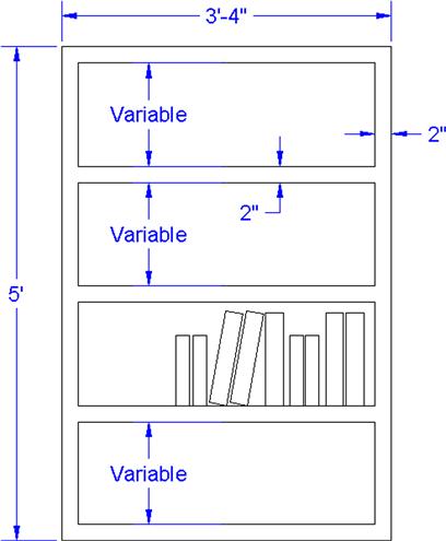
5. Open a new file and set units to Architectural. Draw the following bookshelf. Depending on your exact approach, you may need the rectangle, offset, explode, trim, rotate, copy, scale, and line commands. The spacing of the shelves and the size and rotation of the books can be anything you want. All dimensions are for reference only. (Difficulty level: Intermediate; Time to completion: 10 minutes.)
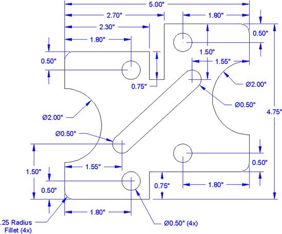
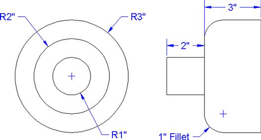
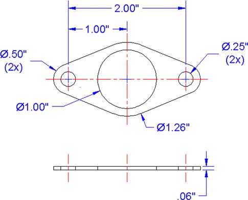
6. Open a new file and set units to Architectural. Draw the following mechanical piece. All dimensions and centerlines are for reference only; we have not yet covered how to create them. You need to use the TANgent OSNAP point. (Difficulty level: Intermediate; Time to completion: 10 minutes.)
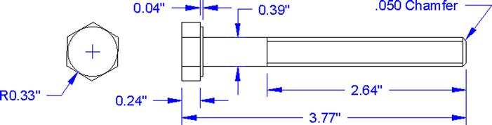
7. Open a new file and leave the units as Decimal. Draw the following simplified bolt diagram. You have all the information needed but may have to carefully project some parts of the side view. You may need the polygon, circle, line, trim, chamfer, and other commands. (Difficulty level: Intermediate; Time to completion: 10 minutes.)
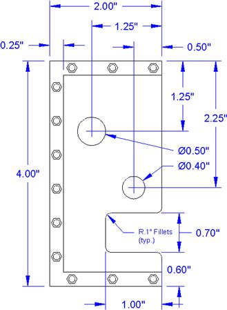
8. Open a new file and leave the units as Decimal. Draw the following fictional bracket. You have all the information needed except for the bolts—you can improvise their sizing and position. You may need the rectangle, circle, line, trim, fillet, polygon, and other commands. (Difficulty level: Intermediate; Time to completion: 20 minutes.)
9. Open a new file and leave the units as Decimal. Draw the following fictional bracket. You may need to use the rectangle, circle, fillet, offset, and other commands. The middle slot is made up of two circles, positioned as shown. Then, two lines are drawn using the TANgent OSNAP, with a trim to complete the slot. (Difficulty level: Intermediate; Time to completion: 30 minutes.)