Hatch Patterns
Learning Objectives
Hatch patterns allow you to indicate a variety of surfaces, from wood to concrete, on your design. In engineering, they are also used to indicate cross-section surfaces. In this chapter, we introduce boundary hatch and discuss the following:
At the end of this chapter, you will be able to add hatch patterns to your floor plan.
Estimated time for completion of chapter: 2 hours (lesson and project).
5.1 Introduction to Hatch
This is a chapter on the concept of boundary hatch or just hatch for short. This is simply a tool for creating patterns and adding fills to your design. These are not merely decorative; rather, they serve an important function of indicating types of materials, ground and floor coverings, and cross sections. As such, this topic is quite important and is the next logical concept to master in AutoCAD.
We cover hatch patterns in two sections. The first is with the Ribbon turned off, which makes the hatch command default to the classic dialog box seen in Figure 5.1. It is easier for a beginner to visualize hatch concepts via this method. It was also the only way to access hatch up until AutoCAD 2011, good to know if you are using an older version of AutoCAD. Starting with AutoCAD 2011 and continuing with 2014, hatch can still be accessed the old way if the Ribbon is not on or, if it is, then via the Ribbon only. The Ribbon essentially duplicates the hatch dialog box, with maybe a few more bells and whistles; we cover this approach as well.
Hatch patterns are not an AutoCAD invention. In the days of hand drafting, there was also a need to visually indicate what sort of material one was looking at. Architects and engineers created easy to understand repeating patterns that somewhat, if not closely, resembled the actual material or at least gave you a very good idea of what it was. Just a few of the uses of hatch patterns follow:
![]() Brick: An important and popular pattern to render the exterior and (sometimes) interior of buildings. AutoCAD has numerous brick patterns available.
Brick: An important and popular pattern to render the exterior and (sometimes) interior of buildings. AutoCAD has numerous brick patterns available.
![]() Herringbone, parquet: Important for flooring designations.
Herringbone, parquet: Important for flooring designations.
![]() Honeycomb: Insulation designation.
Honeycomb: Insulation designation.
![]() Concrete, sand, clay, earth, gravel: All used in designating surfaces in civil and site plan design.
Concrete, sand, clay, earth, gravel: All used in designating surfaces in civil and site plan design.
![]() Various ANSI diagonal patterns: Used to designate the visible inside of an object cut in cross section.
Various ANSI diagonal patterns: Used to designate the visible inside of an object cut in cross section.
With AutoCAD, creating these patterns is easy, as they are all predrawn and saved in a library, which is called up anytime you use the command. Often a designer can purchase or download additional patterns, if the basic ones are inadequate. You can even make your own and save them for future use, although this is a tedious process and only briefly covered in Appendix D.
5.2 Hatch Procedures
At the most basic level, AutoCAD’s hatch command requires only four steps:
Step 1. Pick the hatch pattern you want to use.
Step 2. Indicate where you want the pattern to go.
Step 3. Fine-tune the pattern by adjusting scale and angle (if necessary).
Memorize the four steps and their sequence; this will help you when looking at the Hatch dialog box.
Before we get into the details, it goes without saying that you first need something to hatch. The command will not work on a blank screen or a bunch of unconnected lines. You need a closed area (although later on we violate that rule), and the easiest way to do this is to form a circle or rectangle. Open a new file and draw either of the two shapes. Follow the steps carefully as described next. All advanced hatch functions flow from these basics.
Step 1. Pick the Hatch Pattern you Want to Use
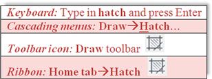
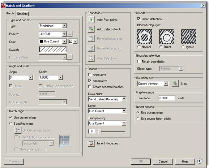
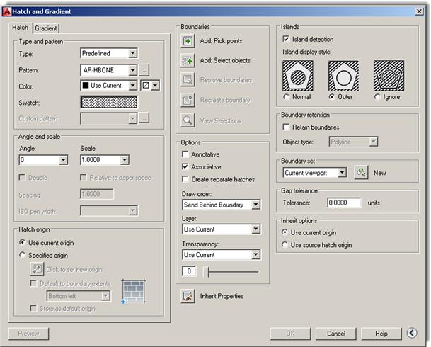
With the Ribbon turned off (Tools→Palettes→Ribbon), begin the hatch command via the keyboard, cascading menus, or icons. The Hatch and Gradient dialog box appears (Figure 5.1). At the bottom right of the dialog box is an arrow that expands or collapses additional options. Make sure it is expanded, as seen in the figure.
Now select a pattern. The choices are listed in the upper left of the dialog box under the heading Type and pattern. Below that are four fields, called Type:, Pattern:, Color:, and Swatch:. Leave Type as Predefined and also ignore Color for now. For the actual pattern selection, if you use Pattern, then select it by name; if you pick Swatch, patterns are selected visually, a much better option. Click on the diagonal lines to the right of Swatch: (or the little box with the three dots to the right of Pattern) and a new box, called the Hatch Pattern Palette, appears (Figure 5.2).
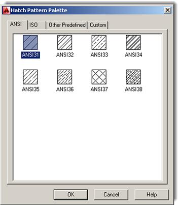
Take a look through the tabs: ANSI, ISO, Other Predefined, and Custom. We have a use for some of the ANSI patterns, not so much for the ISO ones, and Custom is where the custom defined patterns go if you are inclined to create them. We are most interested in the Other Predefined tab. Go ahead and select it; you will see what is shown in Figure 5.3.
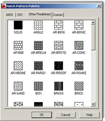
Scroll up and down the patterns. You will notice some of the ones mentioned at the start of this chapter. Go ahead and pick one that you like, preferably one that is distinct and stands out; AR-HBONE is a good choice and is used in this example. When you click on it, the pattern is highlighted blue. Go ahead and click on OK. We are done with Step 1. The new pattern choice is reflected in the Swatch area, as seen in Figure 5.4.
Step 2. Indicate Where you Want the Pattern to Go
You can indicate where to put the pattern in two ways, either by directly picking the object that will contain the pattern or by picking a point inside that object. Which method to use is easy to determine. If the object is actually made of joined-together lines and is one piece (such as your rectangle or circle), then it can be picked directly. If not and the “object” is really just a collection of connected lines defining an area, then the best way is to pick a point in the middle of that area; and indeed this is the more common situation. The pattern then behaves like a bucket of paint spilled in the middle of the room. It flows outward evenly and stops only when it hits a wall. Once again, no holes or gaps are allowed yet; that is addressed later.
In the Boundaries section of the Hatch and Gradient dialog box (top middle), notice the two choices just discussed—Add: Pick points and Add: Select objects. Choose either one to try. The AutoCAD procedure for both is outlined next.
Add: Pick Points
If you choose this option, AutoCAD says:
Click somewhere inside the object, and AutoCAD says:
Press Enter and you return to the Hatch dialog box with Step 2 completed. Notice that a preview of the hatch is shown to you as you complete this step.
Add: Select Objects
Alternatively, if you pick this option, AutoCAD says:
Click on the object itself (not the empty space) and press Enter. You return to the Hatch dialog box with Step 2 completed.
Successfully picking a boundary can sometimes be a tricky business. The existence of gaps, no matter how small, can be a source of occasional frustration to designers; and until relatively recently, it used to be difficult to tell where those gaps were hiding in order to fix them. As of AutoCAD 2010, red circles now appear where the gaps are, aiding you in locating them, but this all can be avoided in the first place by not doing sloppy drafting (i.e., not connecting lines together properly). It is a sign of advanced AutoCAD skills when a complex area hatches right the first time.
In cases where boundary selection is not successful, complex areas can often be broken down to smaller ones by using lines to divide the area into smaller pieces and the nonproblematic portions hatched first, although this is a last resort. A few releases ago, AutoCAD added the gap tolerance command that ignores gaps up to a preset limit. This is a great tool, which we cover shortly, along with the entire gap issue in general, but it is somewhat of a Band-Aid and still does not address the underlying sloppy drafting but merely allows you to get away with it.
Remember, you get only the level of accuracy that you put in. It is essential to master the fundamentals of drafting early on. The hatch command is an “early warning” to students. If they are having problems using it smoothly, they need to go back and refine their basic drafting (linework and accuracy) skills.
Step 3. Fine-Tune the Pattern by Adjusting Scale and Angle (If Necessary)
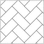
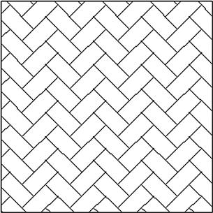
You are almost done and, at this point, could probably just press OK and finish the hatch pattern; however, press Preview instead. It is found at the bottom left of the dialog box and is generally a good habit to get into. What you see is your hatch pattern (if it is the right size) with the object’s border in dashed lines (Figure 5.5).
If everything looks right (as it does in this example), AutoCAD says what to do next:
Go ahead and right-click or press Enter.
Sometimes, however, the pattern is too big or too small. You can usually tell it is too big by either not being able to see it, or seeing a small part of it. If it is too small the problem is worse, because you may not be able to finish the pattern at all. Instead, AutoCAD tells you the following:
Hatch spacing too dense, or dash size too small. Pick or press Esc to return to dialog or<Right-click to accept hatch>:
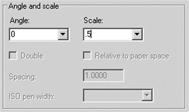
Nothing appears. In either case, press Esc once and you return to the dialog box. Under Angle and scale, change the scale to a larger or smaller number (by typing it in) and preview it again. You may need to do this several times until the hatch pattern is just right. In the same manner, you may adjust the angle of the entire pattern if desired. Angle and scale are shown in Figure 5.6.
Step 4. Preview the Pattern and Accept it if OK
Finally, you are done. Do one more preview and press OK. Note again that a preview was available to you right after Step 2, as your mouse hovered over the area you were planning on hatching. It is still a good idea to do one more preview though before the final OK.
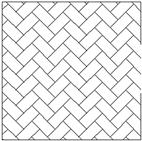
The sample hatch pattern should look like Figure 5.7. Yours may or may not be similar depending, of course, on what pattern and scale you selected, as well as what shape you used.
5.3 Working with Hatch Patterns
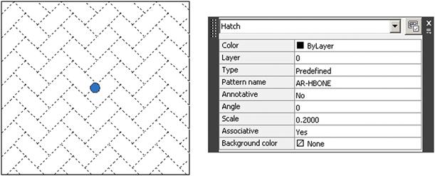
In this section, we mention some of the additional tools and concepts that pertain to hatch patterns. First of all, the most basic question at this point is: How do you edit a hatch pattern after you have created it? It is very easy: To edit a hatch pattern, simply double-click on it. Make sure you get one of the lines of the pattern, not just empty space. You will see a grip and the QuickProperties palette (Figure 5.8); here, you can change whatever you need to. You can, of course, use the full Properties palette if needed as well (recall how from Chapter 3). This is different from older releases of AutoCAD, where you were taken back to the Hatch dialog box. The thinking was that the Hatch dialog box was too big and covered up your work, so a sleeker QuickProperties (or even Properties) palette was a better option. If you are using the Ribbon, to be discussed shortly, you need to click only once to edit the pattern.
Exploding Hatch Patterns
This may be one of the worst things you can do. Never explode hatch patterns; depending on the size, they turn into hundreds of pieces that cannot be put back together again in the same editable form. All the reasons designers give for exploding hatch patterns (making them fit, trimming them, moving the containment border, etc.) can be addressed with additional hatch tools.
Hatch Pattern Layers and Colors
Hatch patterns should be on a generic A-Hatch layer or whatever layer name best describes what the pattern represents (A-Carpet, M-Cross-Sec, C-Gravel, etc.). Choose any color you want for the hatch patterns, though you should not go with anything too bright, as it may overwhelm the design. Shades of gray are common for cross sections in mechanical design, as are various shades of rusty orange for brick. As a side note, hatch patterns can be easily erased by the usual erasing methods. The patterns can also be moved, copied, rotated, and mirrored, although there is rarely a reason to do so.
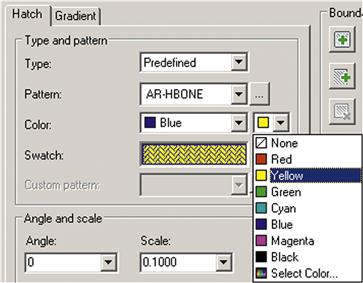
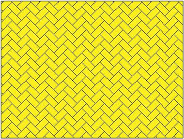
As of AutoCAD 2011, you can now assign a color directly to a hatch pattern regardless of what layer, and associated color, it is on. You can also assign a background color (solid, not a gradient). To do this when first creating the hatch, you can select both the hatch color and the background color (Figure 5.9) from two drop-down menus at the top left of the Hatch dialog box. The same steps can be performed with the Ribbon, as shown a bit later. One sample result of assigning a hatch and background color is shown in Figure 5.10.
Advanced Hatch Topics
Here, we summarize some additional advanced options available for working with hatches, including a more detailed discussion concerning the gap tolerance feature. You should explore these on your own as well; this is an important part of learning AutoCAD and greatly enhances your confidence with the software.
Hatch Origin
This allows you to begin hatch patterns from a precise location (origin) as opposed to a random fill-in. AutoCAD chooses the origin on the pattern itself, and you get to choose to what point on the object that origin is aligned. Try it out.
Options
![]() Annotative: Will not be covered until Level 2.
Annotative: Will not be covered until Level 2.
![]() Associative: Keep this checked. This simply means that, if you move the border, the hatch moves with it; very useful in case of future updates.
Associative: Keep this checked. This simply means that, if you move the border, the hatch moves with it; very useful in case of future updates.
![]() Create separate hatches: If there are multiple separate areas to hatch, this option keeps them separate; sometimes useful, sometimes not.
Create separate hatches: If there are multiple separate areas to hatch, this option keeps them separate; sometimes useful, sometimes not.
![]() Draw order: This is exactly what it sounds like; it gives you options on how you want to stack the hatch and its boundary. Check out the options in the drop-down menu.
Draw order: This is exactly what it sounds like; it gives you options on how you want to stack the hatch and its boundary. Check out the options in the drop-down menu.
![]() Inherit properties: This option lets you borrow the features of another hatch pattern and use them in a new pattern you are creating, saving you some effort and time in picking out a pattern from scratch.
Inherit properties: This option lets you borrow the features of another hatch pattern and use them in a new pattern you are creating, saving you some effort and time in picking out a pattern from scratch.
Islands
This gives AutoCAD guidance on how to interpret boundaries inside boundaries (e.g., a chair in the middle of your floor). It simply tells AutoCAD to ignore them or, if not, how to deal with them. Try drawing another rectangle inside your first one and running through the options represented by the pentagon shapes.
Gap Tolerance
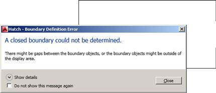
This is a simple and popular tool that was mentioned earlier. Simply set the tolerance to a value big enough to span anticipated holes or gaps in your design and hatch as usual. Initially, if your tolerance is set to 0 units and you try to hatch an area with a gap, you get Figure 5.11.
Close the alert and press Esc to continue. Then, returning to the main dialog box, set a value for the gap tolerance (you can use 10 for starters) and rehatch the area. You get another warning, which can be eliminated from future occurrence by checking off Always perform my current choice, as seen in Figure 5.12.
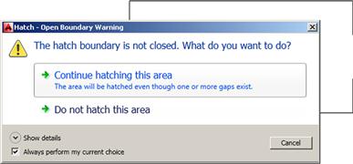
Select Continue hatching this area and AutoCAD temporarily closes the gap to continue the hatch command. After successful completion, the gap shows again but the hatch remains, as seen in Figure 5.13. Some designers have used the command to ignore door openings when hatching carpeting in floor plans. You can try this as well on your floor plan later.
5.4 Gradient and Solid Fill
At the top left of the Hatch and Gradient dialog box, click on the Gradient tab. The left side of the box changes while the right-hand side stays essentially the same, as shown in Figure 5.14.
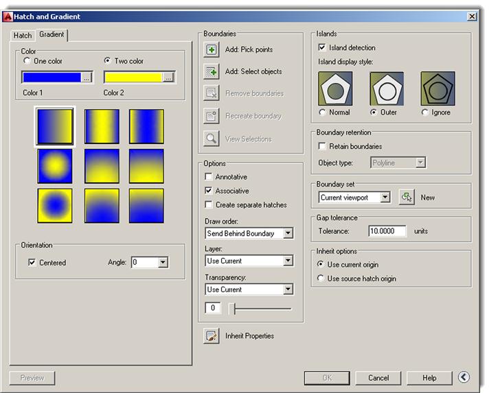
The gradient option is just a solid fill with some flair. You can choose the desired pattern, in one or two colors, and adjust the Shade, Tint, Orientation, and Angle of the gradient. The rest of the steps are similar; Pick point or Select object, Preview, and done.
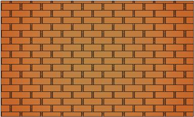
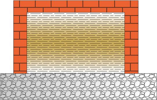
Shown in Figure 5.15 is a possible use for gradient in rendering a brick wall. A brick pattern is created and a brick-colored fill tops it. Note that you may need to use Tools→Draw Order→Bring to Front from the cascading menu to position the brick above the gradient fill (or the gradient fill behind the brick, depending on what you pick first). Try it.
Solid Fill
This fill is the first choice (black box, top left) in the Other Predefined tab and deserves special mention as our final topic.
This solid fill is similar to a gradient but with no fancy color mixing, just one color. It is very handy as a fill for walls, some types of cross sections, or any location where you want a dark area. It becomes even more useful when paired up with a lineweight feature called screening, which is discussed in detail in Chapter 19. It has to do with being able to fade out (or screen) the intensity of any color, typically down to 30%, and is perfect for indicating “area of work” on key plans, some types of carpeting, and even pavement on civil engineering drawings.
A way to mimic this now without screening is to change the solid fill’s color to Gray 9; a soft gray haze is then seen that is distinct and visible, yet not overwhelming. If you are wondering how the walls were filled in on the apartment drawing, this is how.
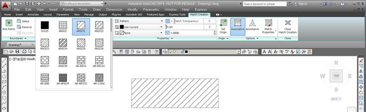
The previous steps using the Hatch dialog box are essentially duplicated using the Ribbon. Bring it back by typing in Ribbon (or Tools→Palettes→Ribbon via the cascading menus). Draw a shape to hatch and begin the command in the same manner as before; you see the Ribbon switch to Figure 5.16. Here, you still have to pick the pattern by dropping down the menu, as seen in Figure 5.17. Note how all the hatch patterns are present and you do not have tabs anymore.
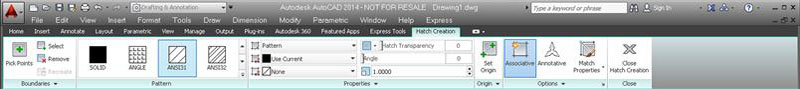
You can then hover your mouse over the area and get an instant preview of the pattern to get an idea of what you have. When you move the mouse away, the pattern disappears. Selection of boundaries is all the way on the left, under Boundaries, and the fine-tuning is in the middle of the Ribbon under Properties. Here, you can select the Scale, Angle (with instant rotation via a slider), and Background Colors. The rest of the features, such as Gap Tolerance, Origin, and others, are found under Origin and Options on the right.
Which method you use is entirely up to you, although if you have the Ribbon up all the time, it makes more sense to continue using it for the hatch command.
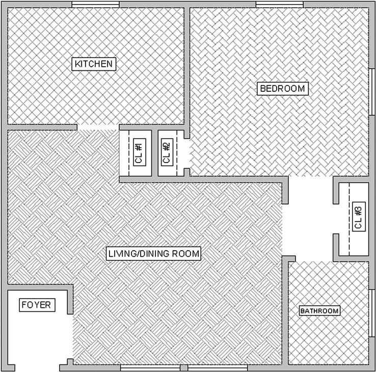
5.5 In-Class Drawing Project: Adding Hatch to Floor Plan Layout
We continue work on the floor plan and add hatch to the rooms and walls. Some tips follow:
![]() To add hatch to rooms, freeze the A-Doors layer and instead draw temporary lines closing off the door entrances. After hatching, remove the lines. You may also be able to use Gap Tolerance set to at least 3 feet, but that is not recommended.
To add hatch to rooms, freeze the A-Doors layer and instead draw temporary lines closing off the door entrances. After hatching, remove the lines. You may also be able to use Gap Tolerance set to at least 3 feet, but that is not recommended.
![]() Make sure the hatch patterns are on the proper layers, whatever they may be (Carpeting or just Hatch_1, Hatch_2; you decide). You do not have to pick the hatch patterns shown, but make sure they are reasonable and at the proper scale.
Make sure the hatch patterns are on the proper layers, whatever they may be (Carpeting or just Hatch_1, Hatch_2; you decide). You do not have to pick the hatch patterns shown, but make sure they are reasonable and at the proper scale.
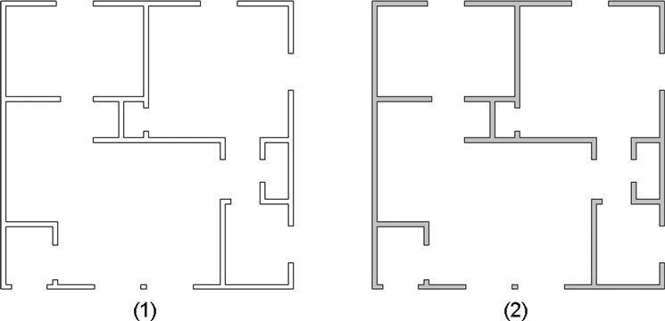
To fill in the apartment walls, freeze everything except the A-Walls and the Hatch layer. Then, use the solid fill, color Gray 9, as described earlier. If you created everything properly, there should be no gaps or breaks in the wall islands. Check to make sure the windows are drawn correctly, meaning the wall has to have an actual closed gap, into which the window is inserted. Figure 5.18 shows what everything should look like prior to wall hatching (1) and right after (2). One possible approach to hatching the apartment is shown in Figure 5.19.
Summary
You should understand and know how to use the following concepts and commands before moving on to Chapter 6:
Exercises
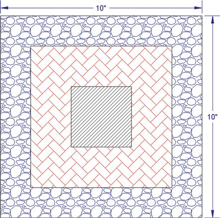
1. In a new file, create the following rectangle, offset to get the smaller ones, and fill them all in with the shown hatch patterns. Do try to duplicate what is shown, including hatch patterns, scale, and angles as closely as possible. (Difficulty level: Easy; Time to completion:<5 minutes.)
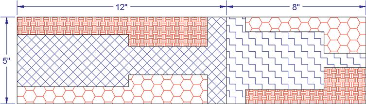
2. In a new file, create the following shapes and hatch patterns. Some overall sizing is shown, but you have to improvise the rest via the offset and line commands. Do try to duplicate what is shown, including hatch patterns, scale, and angles as closely as possible. (Difficulty level: Easy; Time to completion:<5 minutes.)
3. Open Exercise 5 from Chapter 1 and add the following hatch patterns. Do try to duplicate what is shown, including hatch patterns, scale, and angles as closely as possible. (Difficulty level: Intermediate; Time to completion: 10 minutes.)
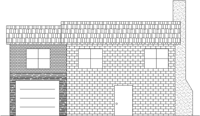
4. Open a new file and set units to Architectural. Create the following brick wall design, a slightly modified version of what is seen on the cover page of this chapter. Note that some of the backgrounds are gradients. Sizing and scale is up to you, but do try to duplicate what you see. (Difficulty level: Easy; Time to completion:<10 minutes.)
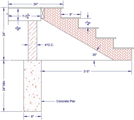
5. Open a new file, create the appropriate layers and set units to Architectural. Create the following stair layout and hatch patterns. Any sizes and dimensions that are not given can be estimated, as can the scale of the patterns. (Difficulty level: Intermediate; Time to completion: 20–30 minutes.)
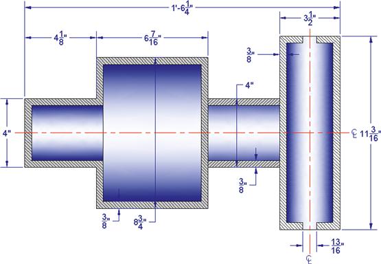
6. Open a new file and set units to Architectural. Create the following layout of a fictional set of cross-sectioned cylinders. Dimensions are provided, but sizing is of secondary importance to creating the hatch and gradient patterns. Notice how gradients are used to depict curvature inside the pipe cross sections, a good trick to add realism to 2D drawings. (Difficulty level: Intermediate; Time to completion: 20 minutes.)