
Advanced Linework
Learning Objectives
In this chapter, we revisit the line concept and expand on it by discussing the following:
By the end of the chapter, you will learn how to use and apply these new types of lines and be able to incorporate them into future design work.
Estimated time for completion of chapter: 2–3 hours.
11.1 Introduction to Advanced Linework
We begin Level 2 in the same way we started Level 1, with the simple line command. At the time, this was enough to start with, and no mention was made of the many other types of lines AutoCAD has. Classroom experience had shown that introducing all the other types of lines at that stage was a sure way to scare off brand-new students, and the other lines were not needed anyway. Now that you are more advanced, we can come back and look at lines in depth.
As it turns out, while the line command is useful for most drawing situations, it is inadequate or inconvenient for a small but important number of other applications. Here, we look at other variants of the line including the pline (polyline), the xline (construction line), its close relative the ray, a special case of the polyline called a spline, an mline (multiple line), and the most unusual one of all, the sketch command.
11.2 Pline (Polyline)
A pline is a regular line with some unique properties:
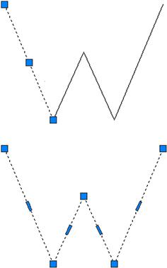
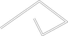
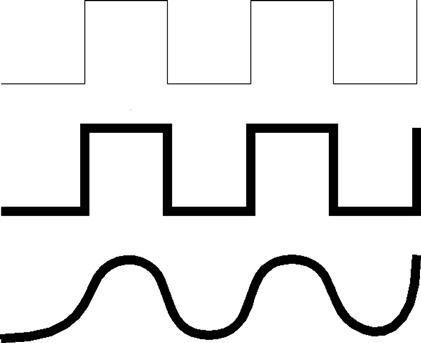
These two properties add tremendous importance and versatility to the old line command, which creates only individual segments that maintain a constant zero thickness. Figure 11.1 provides an illustration of the first property. The top “W” is drawn with four line segments. As you can see, they are all separate, with only the left segment clicked on, and the grips reflect that. The “W” below it is drawn using the pline command and is all one unit, as seen by clicking it once. Notice the slightly compressed center grips.
One example of applying this feature may include drawing lengthy runs of cabling or piping. Then, if the run needs to be deleted, only one click is necessary to remove all the segments. Let us try to draw a pline.
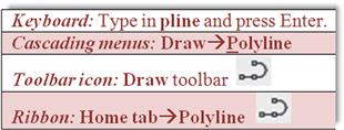
Step 1. Start the pline command via any of the preceding methods.
![]() AutoCAD says: Specify start point:
AutoCAD says: Specify start point:
Step 2. Left-click anywhere on the screen.
![]() AutoCAD says: Current line-width is 0.0000 Specify next point or [Arc/Halfwidth/Length/Undo/Width]:
AutoCAD says: Current line-width is 0.0000 Specify next point or [Arc/Halfwidth/Length/Undo/Width]:
Step 3. Ignoring the lengthy menus for now, click around until you get the same W shape seen earlier.
![]() AutoCAD says: Specify next point or [Arc/Close/Halfwidth/Length/Undo/Width]:
AutoCAD says: Specify next point or [Arc/Close/Halfwidth/Length/Undo/Width]:
When done, press Enter or Esc. Then click on your new pline to see that it is all one unit not separate lines.
Pedit
What if you wanted to apply thickness to the pline (Property 2) or create a pline out of a bunch of lines? For this, you need pline’s companion command, called pedit or polyline edit. Let us try this out on the pline you created and give it thickness. You need to add another toolbar to your collection, called Modify II (Figure 11.2).
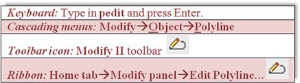
Step 1. Start the pedit command via any of the preceding methods.
![]() AutoCAD says: Select polyline or [Multiple]:
AutoCAD says: Select polyline or [Multiple]:
Step 2. Click on any of the W polyline segments.
![]() AutoCAD says: Enter an option [Close/Join/Width/Edit vertex/Fit/Spline/Decurve/Ltype]
AutoCAD says: Enter an option [Close/Join/Width/Edit vertex/Fit/Spline/Decurve/Ltype]
Type in a small value, say, 0.25, and press Enter. The pline adopts the new width for all segments, as shown in Figure 11.3. You can then press Esc to completely exit out of the pedit command.

Now, try making plines out of lines. Draw the W once again out of ordinary lines, then follow the procedure shown next:
Step 1. Start the pedit command via any of the previous methods.
![]() AutoCAD says: Select polyline or [Multiple]:
AutoCAD says: Select polyline or [Multiple]:
Step 2. Click on any of the W line segments.
![]() AutoCAD says: Do you want to turn it into one?<Y>
AutoCAD says: Do you want to turn it into one?<Y>
Step 3. Press Enter to accept “yes.”
![]() AutoCAD says: Enter an option [Close/Join/Width/Edit vertex/Fit/Spline/ Decurve/Ltype gen/Undo]:
AutoCAD says: Enter an option [Close/Join/Width/Edit vertex/Fit/Spline/ Decurve/Ltype gen/Undo]:
Step 4. Select j for Join, and select all the lines of the W, pressing Enter when done. The collection of separate lines is now a polyline and you may press w for Width as before if you wish. Press Esc to completely exit out of the pedit command.
Another notable option in the pedit command is Spline, and if you press s while in the pedit command, your W will look like Figure 11.4.

To undo this you can press d for Decurve, yet another pedit option. Spline is an important case of a polyline. We look at spline as a separate command later in the chapter.
Exploding a Pline
Plines can be easily exploded using the explode command. The effect is twofold:
Putting it back together requires the pedit command, so explode and pedit are opposites of each other. Be careful though, and do not explode plines unless absolutely necessary, as there may be many individual lines to account for once exploded.
Additional Pline Options
A few more options are worth mentioning with the pline command. First of all, you can start out drawing a pline with a preset width (or half width). Here is the command sequence for that, presented in a shortened “actual” format, as seen from the command line by the user:
Command: pline (via any of the previously shown methods)
Specify next point or [Arc/Halfwidth/Length/Undo/Width]:w
Specify starting width<0.0000>:.25
Specify ending width<0.2500>:.25
Specify next point or [Arc/Halfwidth/Length/Undo/Width]:
Specify next point or [Arc/Close/Halfwidth/Length/Undo/Width]:
As you can see, the W option was chosen and a width of 0.25 was entered for both start and end. If those lengths are not similar, you get something akin to Figure 11.5. In that example, a zero start width was followed by a 0.75 end width to create the triangular first segment of the pline. You can change these widths “on the fly” to create some interesting shapes.

Another option is L for Length. This is similar to Direct Distance Entry from Level 1. Finally, there is the A for the Arc option. This creates arcs on the fly and is very useful for drawing organic-looking shapes for everything from landscape design to furniture to cabling and wiring, as shown in Figure 11.6.
Finally, several releases ago, AutoCAD introduced some additional tools to work with plines (including unexploded rectangles, which are plines by definition). These tools come in the form of a new menu, which appears when you hover the mouse over a grip belonging to a pline or a rectangle (Figure 11.7).
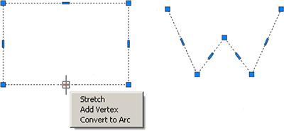
As you can see, you can stretch, add a vertex, or even convert the line to an arc, allowing some new design possibilities and even saving some time.
Stretch
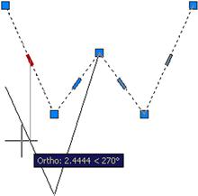
This option, also covered as a separate command in Chapter 15, allows for stretching that particular line and anything attached to it in one of several ways, with one possibility seen in Figure 11.8.
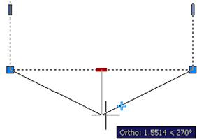
Add Vertex
This option allows you to “break” the line with the addition of another control point (grip), as seen in Figure 11.9. You can then create two angled lines out of one straight line.
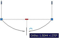
Convert to Arc
This somewhat similar option also adds a vertex but one that allows an arc to be formed as seen in Figure 11.10.
11.3 Xline (Construction Line)
From the relatively involved pline, we swing over to the very simple xline. This is a continuous line that has no beginning or end. The zoom command has no effect on it. The construction part of the name refers back to the days of hand drafting, where you would draw, in light pencil, a guideline that stretched from one end of the paper to the other and was used as a reference starting point for a string of elevations (or anything else) to be drawn one after another.
To use it, make sure Ortho and OSNAP are not activated, and do the following:
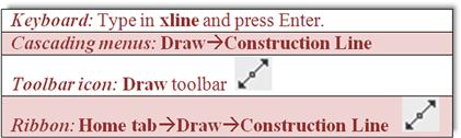
Step 1. Start the xline command via any of the previous methods.
![]() AutoCAD says: Specify a point or [Hor/Ver/Ang/Bisect/Offset]:
AutoCAD says: Specify a point or [Hor/Ver/Ang/Bisect/Offset]:
Step 2. Click anywhere and an xline appears.
![]() AutoCAD says: Specify through point:
AutoCAD says: Specify through point:
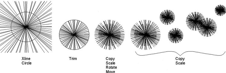
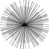
Step 3. Click randomly anywhere along the screen and multiple xlines appear. Figure 11.11 shows one result of clicking in a circular manner.
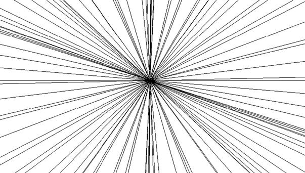
Figure 11.11 is perhaps not the most useful of creations, but landscape designers may find some use for the result of placing a circle at the intersection of those lines and trimming. Then, via some creative scaling, rotating, and copying, you get the reasonable representation of trees or shrubs in Figure 11.12.
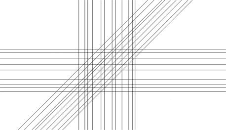
As seen in the menu that follows the xlines, you can also create perfectly horizontal, vertical, or angular xlines. The same can be accomplished by having Ortho on, although the options allow you to create multiple xlines more easily. Clear your screen, start up xline again, and when you see the following menu, try out the various options (results are seen in Figure 11.13): Specify a point or [Hor/Ver/Ang/Bisect/Offset]:
11.4 Ray
A ray is simply an xline but infinite in only one direction. It is easy to use and quite similar to xline, except there are no options for horizontal, vertical, or angular; to get a perfectly straight ray, you just turn on Ortho.
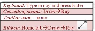
Step 1. Start the ray command via any of the preceding methods.
![]() AutoCAD says: Specify start point:
AutoCAD says: Specify start point:
Step 2. Click anywhere and a ray is created (Figure 11.14).
11.5 Spline
Spline is a unique and valuable command. Its origins are in the mathematical field of numerical analysis, and it is called a piecewise polynomial parametric curve (or a NURBS curve, nonuniform rational B-spline). While knowing the details is not necessary for using this command, what is important is that a spline is ideal for approximating complex shapes through curve fitting. What you do is create a path made out of point clicks, and AutoCAD interpolates a “best-fit” curve through those points.
The result is a smooth, organic shape useful for a great number of applications, from contour gradient lines in civil engineering to landscape design to electrical wiring and many other shapes and objects. The term spline, by the way, comes from the flexible spline devices used by shipbuilders and draftspersons to draw smooth shapes in precomputer days. To draw a spline, do the following:
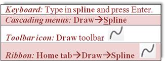
Step 1. Start up the spline command via any of the preceding methods.
![]() AutoCAD says: Current settings: Method=Fit Knots=ChordSpecify first point or [Method/Knots/Object]:
AutoCAD says: Current settings: Method=Fit Knots=ChordSpecify first point or [Method/Knots/Object]:
Step 2. Click anywhere and a spline appears.
![]() AutoCAD says: Enter next point or [start Tangency/toLerance]:
AutoCAD says: Enter next point or [start Tangency/toLerance]:
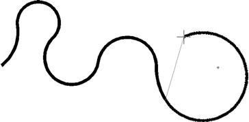
Step 3. Click on another point somewhere on the screen, in an up and down wave pattern, as seen in Figure 11.15.
![]() AutoCAD says: Enter next point or [end Tangency/toLerance/Undo/Close]:
AutoCAD says: Enter next point or [end Tangency/toLerance/Undo/Close]:
As early as this step, you can select c for Close to close the spline tool. In this case, however, continue with the spline curve to add more points.
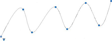
Step 4. Click on a few more points in a similar wave pattern. AutoCAD keeps saying the same thing as in Step 3. Continue clicking several more times (refer again to Figure 11.15). When done, simply press Enter.
This is your basic “out-of-the-box” spline. Notice how, as you click on points, AutoCAD fits a smooth curve that best approximates the path. Each grip in Figure 11.15 represents a click of the mouse, a control point. You can manipulate the positions of these grip points in the standard manner, with the spline following suit. This makes the spline a very flexible tool, adjustable to the exact demands of the designer. Try activating the grips and moving them around.
The command was redesigned somewhat back in AutoCAD 2011, and many of its advanced features are hidden away in submenus, which is a good thing, as most users need only the basic spline and not extensive options for tangencies and other details.
That is not to say they are not there if needed. Click on the down arrow on the bottom left of the spline (grips enabled), and select Show Control Vertices, which is another way to design the spline, useful for 3D work. Go over the various other options on your own with the Help files; there are too many to go into here, but learning them helps you understand this very intriguing command.
Through the examination of spline, you should now have a good idea of how to create and control it. The points of the spline do not have to be random. You can set up a framework for the shape and use OSNAPs to precisely place where you want the spline to go, as shown in Figure 11.16. What you see here are four lines, representing a framework. Then, using OSNAP points, a spline is added in click by click, from an endpoint to a midpoint to another midpoint, then to the final endpoint, at the bottom left.
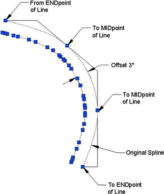
A spline can then be offset using the standard offset command, although be careful in areas where the spline takes a sharp turn. If the offset distance is too great and the spline cannot make a smooth turn after the offset, it breaks down into separate lines. The offset spline also has many more grip and control points than the original spline. A 3" spline offset, with all grips enabled, can be seen in Figure 11.16.
Examples of spline use are numerous. Already mentioned were contour lines (the Chapter 11 cover image), electrical wiring, piping, network cables, landscape design (golf courses, curved driveways, and walkways), interior design (Jacuzzis, swimming pools, furniture); and much more can be constructed with this tool.
11.6 Mline (Multiline)
A multiline is a very useful tool that does pretty much what you would expect from the name: It is used to draw multiple lines all at once. This, in theory, should save you time when drawing everything from architectural walls to multilane highways. As we see soon, the basic mline is easy to draw but not too useful. The trick is to set it up for useful applications using additional tools, as outlined in the next sections. Try out the basic mline to get a feel for it, as shown next.
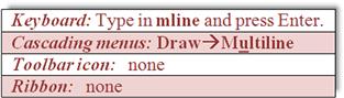
Step 1. Start up the mline command via any of the preceding methods (no toolbar or Ribbon is available).
![]() AutoCAD says: Current settings: Justification=Top, Scale=1.00, Style=STANDARD Specify start point or [Justification/Scale/STyle]:
AutoCAD says: Current settings: Justification=Top, Scale=1.00, Style=STANDARD Specify start point or [Justification/Scale/STyle]:
Step 2. A generic mline appears. Click again.
![]() AutoCAD says: Specify next point or [Undo]:
AutoCAD says: Specify next point or [Undo]:
You can continue in this manner until finished. The default distance between the lines is 1.0, and of course, if the mline is too small or too large, you can zoom in or out. Figure 11.17 shows what you should see after properly executing the previous steps.
Modifying the Mline
While simple, the preceding was not too useful. Specifically, you may want to change one or more of the following properties:
All these and more can be input and modified, thereby making the mline more useful and sophisticated. The key command for setting up mlines is mlstyle.
Mlstyle (Multiline Style)
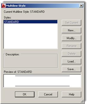
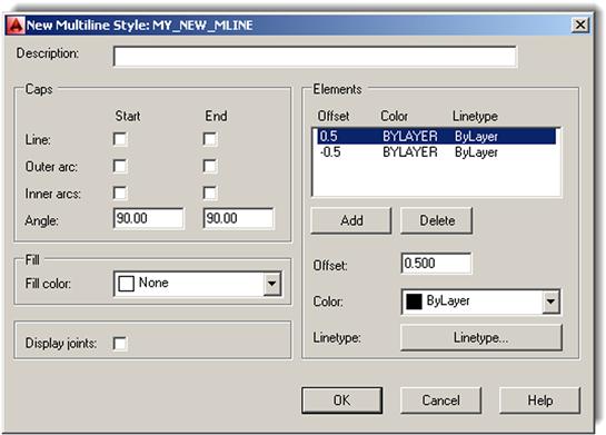
The multiline style command opens a dialog box that allows you to set all the preceding parameters. Type in mlstyle and press Enter or select Format→Multiline Style… from the cascading menu (there is no toolbar or Ribbon alternative). The dialog box shown in Figure 11.18 appears.
Let us create a new style. Press New… and you see a smaller Create New Multiline Style box. Type in a name for your mline (no spaces allowed in the name; use underscores if needed), and press Continue. You then see the main dialog box shown in Figure 11.19. The name created for this example was a generic MY_NEW_MLINE.
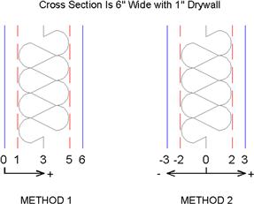
We can now go through the essential changes to the mline. Our goal is to create a typical wall used in construction (see Figure 11.20), often shown in cross section in architectural elevations. For simplicity, it is 6" wide and features a 1" drywall panel on either side, with insulation in between, and room for a wooden stud (not shown here).
This mline, once set up, can be used to draw building walls faster and easier than offsetting and changing properties one line at a time. The process to do this follows.
Step 1. You first need to determine the number of lines making up the mline, and the distances between those lines.
Both of these can be set inside the Elements area (right-hand side) of the New Multiline Style dialog box using the Add button and the Offset field. The idea is to add more line elements (via the Add button) and enter an offset distance for each of these line elements (via the Offset field). This offset distance spaces the lines at the desired interval to create the wall.
Before you do all this, however, you need to decide what the origin of the offset is. This is your starting point for the offsets. The two choices are positioning zero all the way on the leftmost line element (then, all values are positive) or in the middle element (then, half the values are negative). With the first choice, the outer walls are at 0 and 6, and with the second choice, they are at−3 and+3, as shown graphically in Figure 11.21.
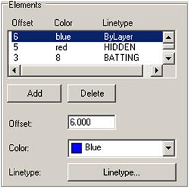
For this example, choose Method 1, and after adding additional lines, for a total of six, set the walls to 0, 1, 3, 5, and 6 units (there are no feet or inches in these settings; you use decimal units, representing inches, throughout).
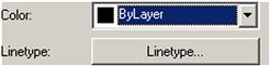
Step 2. Next you need to determine the linetypes and colors making up the lines of the overall mline.
Both of these can be set in the Elements area using the Color: drop-down menu and the Linetype… button, as shown in Figure 11.22. Simply highlight the line element you wish to change and select a new color or linetype. Remember that you may not have the linetypes loaded yet, so you may need to do this (refer back to Chapter 3 for a reminder).
In Figures 11.20 and 11.21, the outer wall color was selected to be blue and the inner walls are red with a hidden linetype. The centerline is a special linetype, often used for insulation, called BATTING. Feel free to choose your own colors and linetypes; those shown are just for illustration, but they are a good starting point. Figure 11.23 shows the Elements area as you go through Steps 1 and 2.
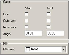
Step 3. As the final step you can add in fills and start/end caps.
End caps, as the name implies, are various ways to finish the start and end of your mlines. You can add regular lines or two types of arcs. Often mlines are joined to each other, so these may not be necessary. You can also add color fills to the mlines, although this is rarely done in practice. All of these can be done via the check-off boxes and drop-down menu on the left-hand side of the New Multiline Style dialog box, as seen in Figure 11.24. You can also display the joints of an mline via a checked box, but that is also rarely called for. This example has no caps or fills, but feel free to experiment on your own.
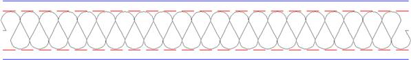
After your new mline has been created, go ahead and click on OK; you are taken back to the dialog box of Figure 11.18, with your new mline previewing in the window at the bottom. The other choice should be Standard, the default mline you created by just typing in mline and saw in Figure 11.17. Set your new mline as the current one (Set Current button), and click on OK. Now, go ahead and type in mline and draw part of a rectangle, as seen in Figure 11.25.
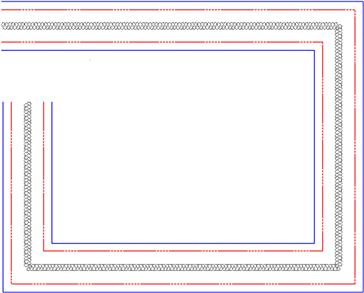
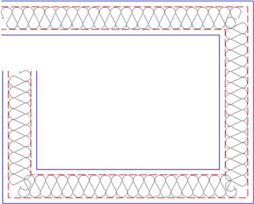
The linetypes may not look right in this example. This is due to a low linetype scale being set. If you recall from Chapter 3, the way to fix this is to type in ltscale and enter a new, more appropriate value. The value used is 4.8. The result is shown in Figure 11.26.
Mledit (Multiline Edit)
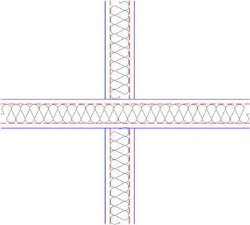
Multiline Edit is a dialog box that deals with the practical applications of mlines, such as how to trim intersecting mlines and how to deal with joints, cuts, and vertexes. To try out some of the features, draw two intersecting mlines, as shown in Figure 11.27.
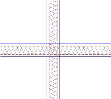
Then, type in mledit, press Enter (or select Modify→Object→Multiline… from the cascading menus), and the dialog box shown in Figure 11.28 appears.

Select Closed Cross in the upper left. The dialog box disappears and you are asked to select the first mline, click on it, then the second mline, and click on that also. After the second click, Figure 11.29 appears. As you can see, the mline’s intersection has been modified.
In the same manner, try out all the features of mledit at your own pace; they are all relatively straightforward and self-explanatory. A cut cuts the line; a vertex adds a “kink” in the mline; Close, Open, and Merge deal with intersections; and so on.
Other Mline Properties
![]() Grips: All mlines have grip points at either the top or bottom of the overall line (this is set using Justification when first creating the mline). Feel free to use these grips to stretch the line around as needed.
Grips: All mlines have grip points at either the top or bottom of the overall line (this is set using Justification when first creating the mline). Feel free to use these grips to stretch the line around as needed.
![]() Exploding the Mline: Mlines can be exploded, which separates them into individual component lines. This may not necessarily be a bad thing. An architectural floor plan may be quite complex, and you may not be successful in getting an mline to do exactly what you want all the time. If the mline is exploded, then you can use the fillet, trim, and extend commands to coax it into the shape you want. Much time has already been saved by using an mline in the first place, so exploding it may be the right solution to finish off the floor plan linework.
Exploding the Mline: Mlines can be exploded, which separates them into individual component lines. This may not necessarily be a bad thing. An architectural floor plan may be quite complex, and you may not be successful in getting an mline to do exactly what you want all the time. If the mline is exploded, then you can use the fillet, trim, and extend commands to coax it into the shape you want. Much time has already been saved by using an mline in the first place, so exploding it may be the right solution to finish off the floor plan linework.
![]() Trim and Extend: Mlines can be trimmed and extended without exploding them (although filleting is not possible). However, an option that pops up is this: Enter the mline junction option [Closed/Open/Merged]<Open>:. The Closed, Open, and Merged options have to do with the intersections, so you need to pick one option to continue the trim or extend. Go through them all as practice.
Trim and Extend: Mlines can be trimmed and extended without exploding them (although filleting is not possible). However, an option that pops up is this: Enter the mline junction option [Closed/Open/Merged]<Open>:. The Closed, Open, and Merged options have to do with the intersections, so you need to pick one option to continue the trim or extend. Go through them all as practice.
![]() Modification of Mlines: Once created, a new mline style cannot be modified once you start using it (but can be beforehand). If you wish to change an mline after you have a few drawn, you need to create a new style that incorporates your desired changes.
Modification of Mlines: Once created, a new mline style cannot be modified once you start using it (but can be beforehand). If you wish to change an mline after you have a few drawn, you need to create a new style that incorporates your desired changes.
11.7 Sketch
This is perhaps one of the most unusual tools in AutoCAD. It allows you to draw objects in freehand. This may seem counterproductive and unnecessary. After all, you spent so much time learning precision and accuracy; but sketch actually finds a wide array of applications, as we soon see.
To truly sketch in freehand on a computer you need bitmap graphics (such as those found in Photoshop®). Then, the maximum resolution is determined by the pixels. In almost all cases, the pixels are so small that it truly seems like you are drawing smooth, continuous freehand lines and shapes. You would have to zoom in pretty close to see what is called pixilation or the breakdown of smooth lines into the little squares (pixels) that make up the drawn geometry.
This is all fine and would be useful for AutoCAD if not for one problem: AutoCAD is a “vector program,” meaning it does not use pixels. Instead, all the geometry is represented by mathematical formulas, which completely describe the shape, size, and location of everything seen on the screen. This approach is necessary for many reasons, not the least of which is to ensure the integrity of the geometry when zoomed in close. So then, how would you sketch in freehand? The solution is simple; instead of pixels, use very short lines, which look continuous if they are small enough and you are not too close to them. This is exactly how sketch works. The command uses small lines, with their size determined by something called a record increment, which we discuss in a moment.
The sketch command has another twist to it. A few releases ago AutoCAD allowed you to turn sketched linework into a spline or a polyline. This can occasionally be useful if you are drawing simple freehand shapes and want maximum smoothness, although the pline option is not recommended, as it adds a tremendous amount of control points to the linework. We discus mostly the “classic” sketch command here.
First, we need to set the record increment to a very small value (use 0.01). Let us try this out.
Step 1. Type in sketch (there is no toolbar icon, cascading menu, or Ribbon for the classic sketch command) and press Enter.
![]() AutoCAD says: Type=Lines Increment=0.1000 Tolerance=0.5000 Specify sketch or [Type/Increment/toLerance]:
AutoCAD says: Type=Lines Increment=0.1000 Tolerance=0.5000 Specify sketch or [Type/Increment/toLerance]:
Step 2. First, make sure Type=Lines, as that is what we want to practice first. If not, press t for Type and select l for Lines. Then, press i for Increment, and press Enter.
![]() AutoCAD says: Specify sketch increment<0.1000>:
AutoCAD says: Specify sketch increment<0.1000>:
Step 3. Type in 0.01 and press Enter.
![]() AutoCAD says: Specify sketch or [Type/Increment/toLerance]:
AutoCAD says: Specify sketch or [Type/Increment/toLerance]:
Step 4. Nothing further needs to be set, so press Enter.
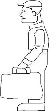
You will see what is essentially a smooth line, green in color, and completely freehand generated. To “lift the pen,” you need to left-click once; then click again to “put it down.” You can also click and hold the left mouse button down when you want to draw, which is more realistic for some. To “set” the drawing, press Enter; the lines turn white (or some other color depending on the current layer). Be careful not to press Esc until you set the lines, as everything disappears. Figure 11.30 shows what you can get after a few minutes of doodling.
As mentioned before, you can also turn the sketched lines into a spline by selecting the Spline option. You will still sketch freehand at first, but upon pressing Enter, the lines smooth out into the familiar spline shapes. The process is the same with the Pline option. You should spend a few minutes experimenting with both. You can also access the Spline option directly via the Ribbon’s Surface tab (look for the spiral on the Curves panel), but for that you need to change the workspace to 3D Modeling.
Applications of Sketch
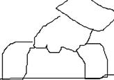
I hope whatever you tried to draw was better than the odd-looking little man with a briefcase. It is not that easy to draw something well with a mouse; occasional erasing and fixing up is needed to get a good sketch. Sometimes, a graphic design tablet and a penlike stylus may be used. Zoom in close on whatever you created and you notice the figure is made up of the small lines we talked about. In the close-up of the hand and briefcase handle in Figure 11.31, you can clearly see the individual line segments. Be careful making a dense drawing. All these lines increase the size of the file very quickly.
Sketch has many applications, which are further expanded via the spline variation of the command. Some examples include:
![]() Architectural elevations featuring sketched people for comparative sizing.
Architectural elevations featuring sketched people for comparative sizing.
![]() Sketched people for traffic sign design and civil engineering studies.
Sketched people for traffic sign design and civil engineering studies.
![]() Trees, shrubs, and other landscape design objects.
Trees, shrubs, and other landscape design objects.
The website www.cben.net is a great source of free sketches, both in plan and in elevation. Figure 11.32 shows a few sketch examples from that website.

11.8 Level 2 Drawing Project (1 of 10): Architectural Floor Plan
Level 2 features a drawing project that is designed chapter by chapter, beginning with this one and completing in Chapter 20. It is an architectural layout, similar to what you did in Level 1,although a bit more involved. The project enables you to put to use all of the cumulative knowledge you acquired up until now and includes features you learn from Level 2 chapters.
The project features many of the basic elements of a “real-world” design and definitely is a step closer to the real thing. You will see a moderately complex floor plan and electrical, HVAC/mechanical, and landscaping plans. You then set up Paper Space and printing with lineweights and other details. A real house design also is likely to feature numerous details, riser diagrams, and sections of doors, windows, and walls. We include some of these elements here and there to increase realism.
Follow all the steps closely, but feel free to embellish the design and get creative. This is excellent practice for the real thing, and if you get through the project smoothly, you will feel right at home with a real design.
Step 1. Open a new file and save it as House_Plan.dwg.
Step 2. Set up units as Architectural, and create the following initial layers. The drawing is monochrome in this textbook for clarity, but you need to follow CAD standards as required in the industry (color suggestions shown). For now, you need:
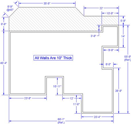
Step 3. Draw the floor plan shown in Figure 11.33. The dimensions are not just for your reference anymore; you also need to draw them in. They serve as checks on your design. Use the proper layers and consistent colors. When done and you are sure everything is correct, freeze the dimensions. It should take you about 30 minutes to set up and complete this design.
Summary
You should understand and know how to use the following concepts and commands before moving on to Chapter 12:
![]() Setting constant width (thickness)
Setting constant width (thickness)
![]() Setting variable width (thickness)
Setting variable width (thickness)
![]() Adding spline curves and decurving
Adding spline curves and decurving
![]() Other pline options (Length, Arc, Offset)
Other pline options (Length, Arc, Offset)
![]() Creating a horizontal, vertical, or angular xline
Creating a horizontal, vertical, or angular xline
![]() Creating a horizontal or vertical ray (with Ortho)
Creating a horizontal or vertical ray (with Ortho)
Exercises
1. Draw a pline with ten segments, each 2 units long and at right angles to each other. Give the pline a thickness of .2 units. Then, spline the pline. The progression is shown in the following figure. Upon completion, decurve the pline and explode it. (Difficulty level: Easy; Time to completion:<5 minutes.)
2. Using xline, circle, trim, copy, and rotate, draw a tree symbol as seen in Figure 11.12, reproduced here. Repeat the same procedure using the ray command. (Difficulty level: Easy; Time to completion:<5 minutes.)
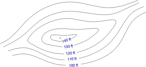
3. Using the spline and text commands, draw contour lines as seen in the chapter cover image and reproduced here. If you wish to create the “gaps” in the splines where the height values are positioned, draw two long vertical lines and trim between them. We cover another method to do this in Chapter 15. (Difficulty level: Easy; Time to completion: 5–7 minutes.)
4. Using the mline, line, and hatch commands, draw a representation of a divided highway, as shown. You have to convert feet and inches to just inches, such as 4"-10"=58", to set up the mline offsets. (Difficulty level: Intermediate; Time to completion: 15–20 minutes.)
