Advanced Dimensions
Learning Objectives
In this chapter, we introduce advanced dimensions and discuss the following:
By the end of the chapter, you will learn additional, advanced features of the Dimension Style Manager and be capable of setting up complex dimensions. We also discuss two advanced dimensioning features called geometric and dimensional constraints.
Estimated time for completion of chapter: 2–3 hours.
13.1 Introduction to Advanced Dimensions
This chapter is meant to complete your knowledge of AutoCAD’s dimensioning features. Specifically, we look at the New Dimension Style (NDS) dialog box and Parametrics. In Level 1, we focused primarily on defining the types of available dimensions and how to properly dimension geometry. Little was mentioned of this dialog box except for the four essential features deemed most important: Arrowheads, Units, Fit, and Text Style (not needed as much anymore, as the better-looking Arial is the default font). In this chapter, we go through the entire NDS dialog box and discuss other options and features, some more than others, according to their usefulness.
The reason you need this knowledge is because AutoCAD allows for a tremendous amount of power, flexibility, and variation with its dimensioning. As a beginner user, you may not come to appreciate what is available, because much of it may already be “set up” for you. As a CAD manager and advanced user (for whom Level 2 is geared), you may be charged with doing this “setting up” and need to know what to do. We conclude the chapter with a new feature introduced back in AutoCAD 2010 called Parametric Dimensions and Constraints. These are routinely found in advanced 3D software but just recently appeared in AutoCAD.
13.2 Dimension Style Manager
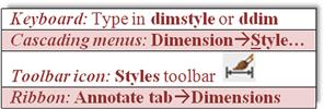
To start off, let us take a closer look at the Dimension Style Manager. You saw it in Chapter 6, so as a reminder, here is how we got it up on our screen.
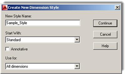
Create a new style, by pressing the New… button, and name it Sample_Style (Figure 13.1). Click on Continue when done. You then see the New Dimension Style dialog box. We now take a much closer look at the seven tabs, titled Lines, Symbols and Arrows, Text, Fit, Primary Units, Alternate Units, and Tolerances.
Keep in mind as we go through these that our goal is not to cover every possible button and menu in extreme detail. Many of the settings are rarely used, and to describe them all completely would take dozens of pages and bewilder even the most dedicated AutoCAD student.
A much better approach is to give a basic overview of each tab and focus on only the features that are of utmost importance and widely used. You will see those features identified and described in more detail, with emphasis on how they fit in with the design process and how they benefit you as an AutoCAD user. If you wish to learn more, use this information as a starting point and consult the Help files.
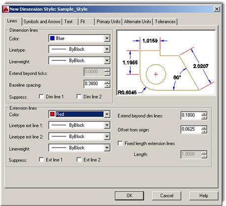
Let us take a look at the first tab, all the way on the left of the New Dimension Style dialog box, called Lines (Figure 13.2). If it is not already visible, click on it to bring it up. Throughout the process, carefully observe the Preview window at the upper right to see the results of changing or adjusting whatever we discuss.
Lines Tab
This first tab is one that most users leave “as is” and generally do not modify. Here, we can make mostly cosmetic changes to two items specifically: dimension lines (upper left) and extension lines (bottom). It is, of course, instructive to know what they are. Dimension lines extend from the numerical value and contain arrowheads or another symbol. The color blue is selected for them in Figure 13.2. Extension lines extend from the part you are dimensioning and “frame” the rest of the dimension. The color red is selected for them in Figure 13.2.
The Lines tab is all about working with these two features. For both the dimension and extension lines, you can change their color, linetype, and lineweight. You simply click on the down arrow and change the property. You can also suppress either or both of the extension or dimension lines, which makes them disappear from view. This has some value if, for example, a dimension is sitting between two walls and the extension lines are not visible anyway. You can then suppress them. This however would be a “local” thing, applied to just that one dimension via the Properties dialog box. There is little use in suppressing either extension or dimension lines for the entire drawing. Next, a few values are presented:
All these values refer to the various spaces between dimension elements or length of elements. They can all be fine-tuned one at a time. However, it is very important to understand that you do not want to do that here in this tab. If you wish to change the size of a dimension, you need to do this by increasing the overall scale, not one element or space at a time. We discuss this in great detail later, when we cover the Fit tab. If you try to adjust the values one at a time, you end up with a lopsided dimension, so leave them all as default.
Finally, we have a check box for fixing the length of an extension line (and assigning a permanent value). This has the effect of placing the dimension a fixed distance from the design but is also rarely used, as it takes away some flexibility in dimension placement.
Just for practice, go ahead and change the colors of the dimension lines to blue and the extension lines to red, as seen in Figure 13.2.
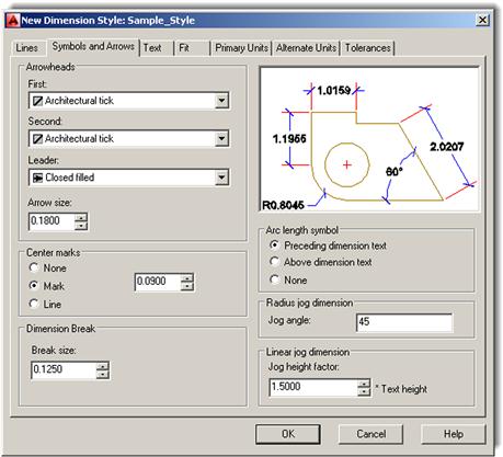
Symbols and Arrows Tab
The most important feature found under this tab is the ability to change the arrowheads of your dimensions (upper left of tab). You already did this briefly in Chapter 6: changed your arrowheads to tick marks. Go ahead and do this again, making a note of the other available choices. You can make the second arrowhead different from the first, of course, but that is rarely done. The leader is generally left as an arrow since its main purpose is to point at something. Just below the leader is a field to change arrow sizing. This also falls under the “do-not-do-it-here” category, as discussed in the previous tab. Arrowheads need to be sized according to the overall scale, not individually. We discuss this under the Fit tab.
Moving below the Arrowheads, we have the Center marks. This has to do with measurements of a circle and what you want to see in the center of one when a diameter or radius dimension is added. Mark or Line is typically selected; let us go with Line. Notice how the Preview window reflects both this and the arrowhead changes.
Below Center marks and to the right, we have some relatively minor options. The Arc length symbol concerns the placement of the symbol, and the Radius jog dimension has to do with the angle of the jog “wiggle.” Leave them, as well as the Linear jog dimension, as default all around. Do the same thing for the Dimension break field. It sizes up or down according to overall scale settings, so leave it as is for now. Your Dimension Style dialog box should look like Figure 13.3.
Text Tab
This tab is all about what dimension text looks like (appearance) and where it goes (placement and alignment). Take a look at the Text appearance category at the upper left. You already practiced changing the text under Text style. The goal was to make the dimension text the same as the rest of the text in the drawing: same font and usually the same size. In Chapter 6, when this was done, the text you selected on the floor plan was Arial 6″.
In this case, create another font from scratch by pressing the button to the right of the Text style: field (button with the three dots) and setting a font style called RomanS .5. You see the Style dialog box, as first outlined in Chapter 4, and need to set the name, font, and size. Review that chapter if you have any problems doing this.
Moving down the Text appearance category, we find
![]() Text color: Usually not set separately and remains “By Layer.” Here, for practice, we set it to the color Magenta, as seen in Figure 13.4.
Text color: Usually not set separately and remains “By Layer.” Here, for practice, we set it to the color Magenta, as seen in Figure 13.4.
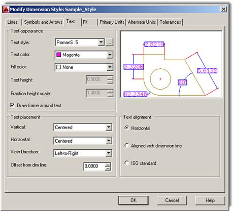
![]() Fill color: Creates a color highlight behind the text. Try it out for practice, but in this example, no fill is set permanently. To add a frame around the text, there is a check box for this further on down, which we check off. Often a fill and a box are used together.
Fill color: Creates a color highlight behind the text. Try it out for practice, but in this example, no fill is set permanently. To add a frame around the text, there is a check box for this further on down, which we check off. Often a fill and a box are used together.
![]() Text height (grayed out): This is not adjusted here. Use the previously mentioned Style dialog box.
Text height (grayed out): This is not adjusted here. Use the previously mentioned Style dialog box.
![]() Fraction height scale (grayed out): This applies to the size of fractions. The field can be set only when architectural units are being used. We look at this setting in detail soon.
Fraction height scale (grayed out): This applies to the size of fractions. The field can be set only when architectural units are being used. We look at this setting in detail soon.
These settings take care of pretty much every text appearance issue. Next, we look at how the text is placed in the drawing.
The Text placement category (bottom left) allows you to position the dimension value in every conceivable way near the rest of the dimension. You can place the values above, below, or centered on the dimension line. You can also move the values around the extension line, lining them up. Experiment with all the possible settings, observing the results in the preview window to the upper right. The default setting for both Vertical and Horizontal is Centered, as seen in Figure 13.4. View Direction: flips the values around, and Offset from dim line: is best left alone and is adjusted as part of the overall scale settings.
With Text alignment (bottom right), the common default is Horizontal, because people generally do not want to tilt their heads to the side every time they check a dimension on a printout. Do try the other two options (aligned and ISO) to see what they do, though. Your Dimension Style dialog box should look like Figure 13.4.
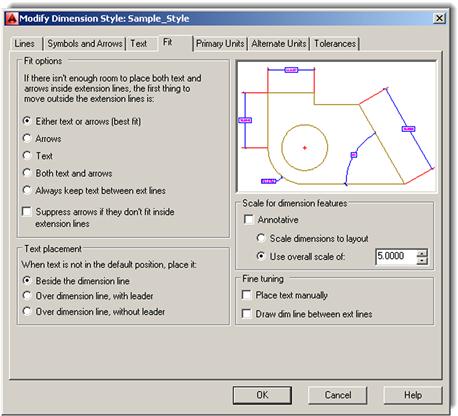
Fit Tab
The contents of this tab can be a bit confusing at first; after all, didn’t we just focus on text placement under the Text tab? Yet, here is another set of categories to fine-tune text placement. You can think of the Fit tab as a continuation of the Text tab with additional Fit options, Text placement, and Fine tuning categories.
Sometimes when you dimension small areas, the extension lines are so close together that the dimension value just does not fit in between them. The Fit options category, at the upper left, simply asks: “If the dimension doesn’t fit, what do you want to move?” The best answer here is to select the first option, Either text or arrows (best fit), and let AutoCAD decide. You can manually force other choices as seen in the listing (arrows, text, etc.), of course, but then this choice is applied to all cases uniformly, which may not always be correct.
You can even suppress arrows if they do not fit between the extension lines, but that is rarely a good idea and makes for some odd-looking dimensions.
The Text placement category (bottom left) is really just a minor setting and should be left in the default first choice. At the very bottom right, we have the Fine tuning category. These two boxes are not all that important, as you rarely want to place text completely manually (adds extra workload) and asking AutoCAD to always draw a dim line between extension lines makes no sense, as the numerical value is then “crossed out.”
The most important category to discuss here is the Scale for dimension features just above the Fine tuning category. You already saw the all-important Use overall scale of: field in Chapter 6 (you entered the value 15). Then, in Chapter 10, “Paper Space,” there was a full discussion of what values go in that field and why. Recall that this value boosts (or lowers) the overall sizing of the dimension, and there is no need to adjust all the individual components that we mentioned in the previous tabs. For now, just enter the value 5.0000.
Your Dimension Style dialog box should look like Figure 13.5.
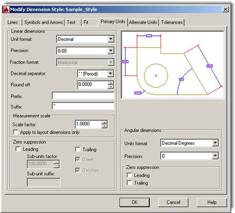
Primary Units Tab
This tab features quite a lot of useful settings. In the Linear dimensions category (upper left), you already practiced changing the Unit format: from Decimal to Architectural in Chapter 6. Generally, the dimension units are the same as the drawing units, so if you draw in architectural feet and inches, you would want to dimension in similar units. For this exercise, we leave the units in Decimal mode. In both cases, the Precision setting just below the units can be set to whatever value is appropriate. The range is 0 to 0.00000000 for Decimal and 0′-0″ to 0′–1/256″ for Architectural. Make a note also of the other units that can be selected, although they are rarely used.
Just below Precision you find the Fraction format:, Decimal separator:, and Round off: fields. The first two should be relatively clear in their function. Fraction format gives you a few choices (Horizontal, Diagonal, and Not Stacked) in how you want the fractions to look if using architectural units. This field is grayed out if using decimal dimensions.
The Decimal separator gives you a few choices (Period, Comma, and Space) in how you want the decimal values to look (European engineers do not use a comma when writing 1,000, for example). This field of course is grayed out if using architectural dimensions. You do not want to use Round off: at all. This field of course is grayed out if using architectural dimensions. Some other features further down the column are outlined next.
![]() Prefix/Suffix: Very useful features allowing you to add text, symbols, or values before and after the dimension values. We add the inch symbol in the suffix as an example.
Prefix/Suffix: Very useful features allowing you to add text, symbols, or values before and after the dimension values. We add the inch symbol in the suffix as an example.
![]() Measurement scale: Scales dimension values; not necessary in common usage.
Measurement scale: Scales dimension values; not necessary in common usage.
![]() Zero suppression: Another very useful feature allowing you to suppress zero values either before or after the main significant digits when using decimal units. For example, a 0.625 value becomes just .625 and a 1.250 becomes 1.25. This is used in conjunction with the Precision setting to “clean up” dimension values, removing extra zeros. With the Architectural units setting, the idea is the same but now 0 feet and 0 inches are suppressed.
Zero suppression: Another very useful feature allowing you to suppress zero values either before or after the main significant digits when using decimal units. For example, a 0.625 value becomes just .625 and a 1.250 becomes 1.25. This is used in conjunction with the Precision setting to “clean up” dimension values, removing extra zeros. With the Architectural units setting, the idea is the same but now 0 feet and 0 inches are suppressed.
The final category is Angular dimensions (bottom right). Here, you can select other units for angles such as Gradians, Radians, and Degrees/Minutes/Seconds (useful for surveyors). For most uses, however, Decimal Degrees are sufficient and the Precision: field below that allows for setting 0 to 0.00000000. Angular dimensions can also have zero suppression, leading and trailing.
Run through all the options available and, when done, set your Dimension Style dialog box to what is shown in Figure 13.6.
Alternate Units Tab
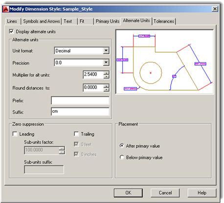
This is a tab we did not explore at all in Level 1. Alternate units are a secondary set of dimensions that reside inside parentheses attached to the main set of units. Their purpose is to present the main units in an alternate form such as metric versus English (just one example).
The first thing you must do, as you click over to the Alternate Units tab, is to turn on the alternate units if they are all grayed out. Check off Display alternate units at the upper left, and the entire tab activates and the fields become editable. Most of our discussion centers on the Alternate units category (upper left). The Zero suppression and Placement categories should be familiar by now.
Under this category, we have:
Most of these should also be familiar to you, such as Unit format and Precision. These values generally match the main set of units. Skipping Multiplier, we have Round (never a good idea to use) and finally the previously explained Prefix: and Suffix: fields.
Understanding alternate units then boils down to fully grasping the Multiplier for alt units: concept. It is a powerful and simple idea. Instead of presenting a collection of “canned” multipliers, AutoCAD allows you to set your own. So, if the main unit is 1 mile, to express this in feet (as an alternate unit), type in 5280 as a multiplier. You are in no way limited as to what sort of value you can enter (inches to miles or millimeters to yards is completely acceptable, if not necessarily practical), but of course you have to know exactly what the multiplier is or else, as they say, “garbage in, garbage out.” Therefore, an incorrect multiplier gets you false alternate unit readings.
Explore all the features of Alternate units, and try entering several multipliers. For example, the number of yards equal to 1 mile (1760). Note also the default multiplier: 25.4. That is how many millimeters there are in an inch; this is useful for the most common application of alternate units, which is presenting metric units next to English ones.
In our case, let us go with the amount of centimeters in an inch (2.54) and enter that as the alternate unit. Also add cm in the suffix. Your Dimension Style dialog box should look like Figure 13.7.
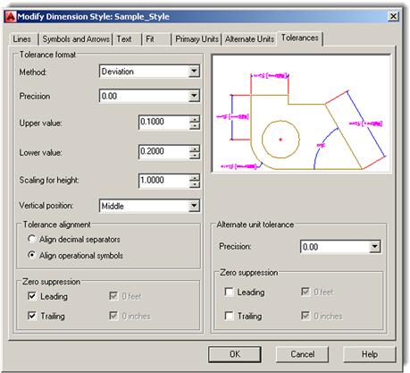
Tolerances Tab
This final tab also has not been examined yet. Tolerances are generally defined as deviations from an ideal stated value, as used in manufacturing specifications of engineering devices. Tolerances are relevant mostly to engineering and manufacturing and less so to architecture, but knowledge of this tab is useful for all AutoCAD students.
The underlying need for specifying tolerances hinges on the fact that, in manufacturing, closer tolerances may be costlier to achieve, while larger tolerances, although cheaper, may adversely affect performance of a part. Tolerances are a way of expressing just how much a part may be off the mark and still be acceptable, based on engineering need and cost analysis. Aerospace, automotive, and biomedical engineering tolerances are closer than most consumer products, for example.
Tolerances are a familiar topic to mechanical engineers and machinists. To them, no further explanation is needed, and AutoCAD’s tolerance choices are familiar: Symmetric, Deviation, Limits, and Basic. Other options under this tab, such as Zero suppression and Placement, should look familiar to all. A short description of each type of tolerance is presented next:
![]() Symmetric Tolerances: These indicate the overall deviation, which is symmetric for upper and lower values; therefore, you set only one (the upper value).
Symmetric Tolerances: These indicate the overall deviation, which is symmetric for upper and lower values; therefore, you set only one (the upper value).
![]() Deviation Tolerances: These indicate nonsymmetrical deviations in either direction with a stacked±.
Deviation Tolerances: These indicate nonsymmetrical deviations in either direction with a stacked±.
![]() Limits Tolerances: These are similar in theory and indicate the acceptable limit in one or both sets of values, but no±is shown.
Limits Tolerances: These are similar in theory and indicate the acceptable limit in one or both sets of values, but no±is shown.
![]() Basic Tolerances: These are the same as none, the first choice.
Basic Tolerances: These are the same as none, the first choice.
Tolerances are an interesting topic to explore further, but because a large percentage of this textbook’s readers will not need them in their current or future work (as related to architecture), we do not go any further in depth. If you wish to learn more, there is a tremendous amount of information online. For now, feel free to experiment and set your tolerance to Deviation, as seen in Figure 13.8.
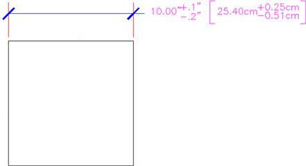
So what did we end up with after all these settings? Well, in the interest of trying out as much as possible, we did not really create a very realistic looking dimension. Let us take a look at it. Click on OK in the Dimension Style box; it will disappear and take you back to the Dimension Style Manager. Then, press Set Current in the next box, followed by Close. Now draw a 10″×10″ rectangle and dimension it using the basic Horizontal dimension. It should look similar or close to Figure 13.9.
Let us try another sample dimension on a hypothetical section of roadway. Draw something similar to Figure 13.10, with the two vertical lines 3 units apart. Run through all the tabs again, using the following data:
![]() Primary units: Decimal. Precision=0.
Primary units: Decimal. Precision=0.
![]() Suffix added on main units→mile(s) and alternate units→feet.
Suffix added on main units→mile(s) and alternate units→feet.
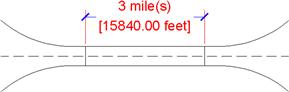
You should get a result similar to Figure 13.10. Note how simple it is to use alternate units if you know the multiplier.
13.3 Introduction to Constraints
AutoCAD was always a top-notch 2D drafting software application but one with a bit of an inferiority complex. Not in regards to any other 2D competitors but rather toward 3D solid modeling and design software. These sophisticated products were developed in their own world, apart from AutoCAD, via development firms that never competed against or had anything to do with Autodesk or architecture. These programs included CATIA, NX, Pro-Engineer (now called Creo), and SolidWorks among others. Their developers invented quite a few revolutionary concepts and methods that transformed the way engineering design is done. Autodesk eventually jumped on board with Inventor and later Revit, both of which are excellent 3D products (one for engineers and the other for architects).
That left the AutoCAD development team looking at how its software could be enhanced by incorporating some of these sophisticated 3D tools without fundamentally altering AutoCAD’s identity or formula for success. If you go on to study AutoCAD 3D, you will notice how many “borrowed” concepts found their way into the software as AutoCAD reached ever further into the high-end 3D world.
Some of these concepts also found their way into 2D, such as the ones we are about to discuss, namely, Parametrics, which is really two topics: Geometric constraints and dimensional constraints; the latter is also referred to as dimension-driven design. If you are an engineer or an engineering school student who used the previously mentioned 3D solid modeling software, you quickly recognize these concepts. AutoCAD literally took a page out of their playbook. Let us discuss each concept separately.
13.4 Geometric Constraints
The fundamental idea behind geometric constraints, regardless of what software we deal with, is to restrict (constrain) the possible movement of drawn geometry and force that geometry into certain positions. Ortho is a horizontal and vertical constraint on lines. So, if you want two parallel or perpendicular lines, a constraint can be placed on them that forces them to always stay parallel or perpendicular as well as to be that way in the first place. Expanding to more general terms, geometric constraints set “relationships” between geometries, such as parallel, perpendicular, tangent, and coincident.
This overall concept is quite important in setting what is referred to as design intent. If a drilled hole in a bracket absolutely has to be concentric to the bracket’s corner fillet to fulfill the design intent, then that is the main driving factor in its design (concentric means the circles and arcs share the same center point). Other aspects of the design, such as perhaps notches and other geometry on the bracket, however, may be less critical. The constraints then “hold” the critical geometry, while you design the rest around it.
This is a very simple example; with a bracket, you can probably keep track of the critical relationships without help. Geometric constraints really earn their keep with more complex designs, where many constraints are needed to preserve design intent. Without them, it would be easy to forget one or two important relationships and discover later down the road that the part you are working on does not function properly because a tangency somewhere was not preserved.
Almost since the beginning of high-end 3D software, geometric constraints were an important part of the design approach, but they were not included in AutoCAD until recently (release 2010); and AutoCAD designers needed to keep track, and check over, their geometric relationships manually. With these new tools, AutoCAD’s engineering and architecture design capabilities have been greatly enhanced.
Types of Geometric Constraints
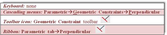
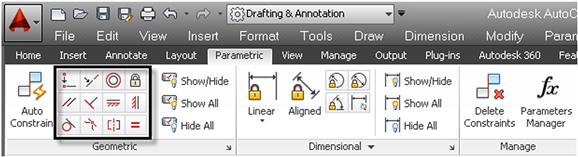
Listed next are most of the constraints available to you. We do not go through every single one but cover only the more commonly used ones, leaving the rest for you to explore. The best way to set constraints is via the Geometric Constraints toolbar (see Figure 13.11) or the Ribbon’s Parametric tab.
The critical constraints we discuss are:
![]() Perpendicular: Constrains two lines or polylines to perpendicular 90° angles to each other.
Perpendicular: Constrains two lines or polylines to perpendicular 90° angles to each other.
![]() Parallel: Constrains two lines to the same angle.
Parallel: Constrains two lines to the same angle.
![]() Horizontal: Constrains two lines to lie parallel to the X axis.
Horizontal: Constrains two lines to lie parallel to the X axis.
![]() Vertical: Constrains two lines to lie parallel to the Y axis.
Vertical: Constrains two lines to lie parallel to the Y axis.
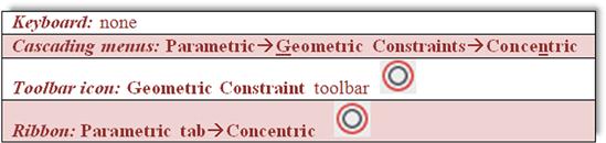
![]() Concentric: Constrains circles, arcs, or ellipses to maintaining the same center point.
Concentric: Constrains circles, arcs, or ellipses to maintaining the same center point.
![]() Tangent: Constrains a tangency between curves and lines.
Tangent: Constrains a tangency between curves and lines.
![]() Coincident: Constrains two points together (to be discussed along with dimensional constraints).
Coincident: Constrains two points together (to be discussed along with dimensional constraints).
Adding Geometric Constraints
Adding geometric constraints involves simply picking the constraint you wish to add and selecting the first object (which serves as the reference point) followed by the second object. The constraint then appears next to the objects, reminding you it is set. The constraint tool also forces the objects into that constraint, so if you draw two lines that are not quite parallel, once you set the constraint, they become parallel right away.
Having read this, you may be tempted to completely do away with Ortho and even OSNAP to create accurate geometry, allowing constraints to “fix” drawn shapes. This is not generally recommended, of course, as sloppy drafting catches up to you sooner or later (though we do try this in the next example). While geometric constraints are very useful new tools, use them when appropriate, without forgetting or throwing away basic accuracy habits.
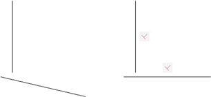
Let us try this out with the first constraint on the previous list: Perpendicular.
Step 1. Draw two lines that are roughly perpendicular, as seen in Figure 13.12 (left).
Step 2. Select the perpendicular geometric constraint via any of the preceding methods.
[Horizontal/Vertical/Perpendicular/PArallel/Tangent/SMooth/ Coincident/CONcentric/COLlinear/Symmetric/Equal/Fix]<CONcentric>:_Perpendicular
Step 3. Select the first line (the vertical one).
Immediately after the selection of the second line, you see it snap to perpendicular and two sets of geometrical constraints are added next to each line, as seen in Figure 13.12 (right). Note that, if you were to select the bottom line first, then the vertical one would snap to it, not the other way around. Selection order matters.
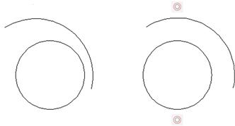
Let us try one more, the concentric one. We leave the rest as an in-class exercise.
Step 1. Draw a circle, then an arc above it, as seen in Figure 13.13 (left).
Step 2. Select the concentric geometric constraint via any of the preceding methods.
[Horizontal/Vertical/Perpendicular/PArallel/Tangent/SMooth/ Coincident/CONcentric/COLlinear/Symmetric/Equal/Fix]<CONcentric>:_Concentric
Immediately after the selection of the arc, you see one or both snap to a concentric setting (their centers are the same), as seen in Figure 13.13 (right). Note that, if you were to select the arc first, the circle would adjust to it, not the other way around. Once again, selection order matters.
Try out the remaining geometric constraints on your own as an in-class exercise.
Hiding, Showing, and Deleting Geometric Constraints
There are two ways to access these additional options to work with constrains. You can either right-click on one of the constraints to reveal a small menu, as seen in Figure 13.14, or find the same options on the Ribbon, as seen in Figure 13.15, along with the rest of the constraints.
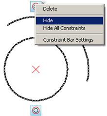
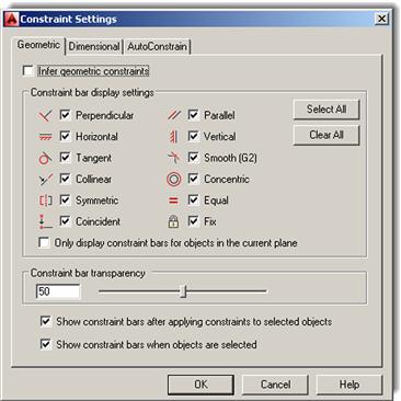
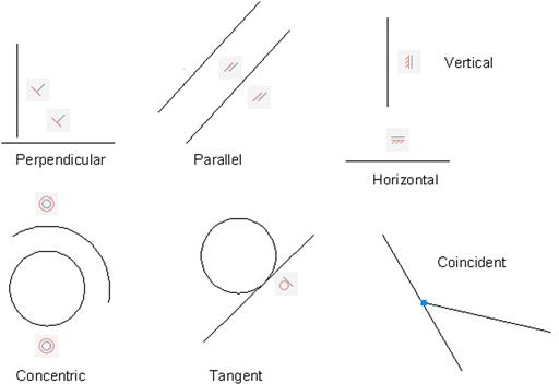
The Constraint Settings dialog box, which can be accessed via the small drop-down arrow at the bottom right of the Geometric tab, is actually just for global settings, for which geometric constraints to show. Leave all the choices selected and the transparency at 50%, as seen in Figure 13.16. Finally, Figure 13.17 shows all seven of the constraints mentioned, as you should see them on your screen after completing the in-class exercise.
13.5 Dimensional Constraints
Since we already discussed the basic idea of constraints, this introductory section is shorter. The idea here is to move from constraining pieces of geometry (and their positions relative to each other) to constraining the actual dimensions of the drawn design. So, if two circles, representing drilled holes, absolutely need to be 3″ apart, then constraining that dimension ensures it does not change regardless of what other design work goes on around them.
Dimensional constraints are also a major part of 3D parametric design and can be easily transferred to 2D work, as was done here in AutoCAD. Also, because the geometry has to obey the constrained dimension, you can change the geometry by simply changing the dimension value, which is quite a departure from the normal order of business with AutoCAD. This ability to change geometry by updating dimensions is called dimension-driven design. With high-end 3D solid modeling software this is really the only way to change the size of an object (usually called a feature). AutoCAD lacks this ability in 3D but, as just mentioned, can do this with 2D shapes.
At this point, you may start to see why all the preceding is referred to as parametric design. We are designing by changing or assigning parameters to our geometry. The geometry itself is almost secondary to the relationships and data that drive its existence and creation. This type of philosophy and approach is one of several steps critical to assuring that what we have is a valid engineering design, not just a pretty picture. The data behind the design has to make sense.
Working with Dimensional Constraints
Learning the basics of dimensional constraints is straightforward. You can either add them in right away to your design or convert existing regular dimensions to constraints. Dimensional constraints have their own toolbar (Figure 13.18), or they can be accessed through the Ribbon (Figure 13.19).
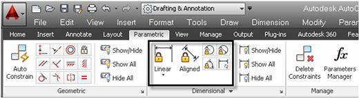
The available dimensional constraints mirror the regular dimensions closely:
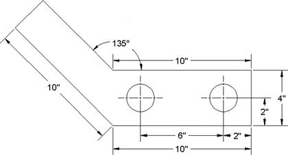
To practice them, draw the bracket seen in Figure 13.20, but do not dimension it; use the shown values only to create the geometry.
Now add a horizontal dimensional constraint.
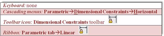
Step 1. Start up the dimensional constraint via any of the preceding methods.
![]() AutoCAD says: Specify first constraint point or [Object]<Object>:
AutoCAD says: Specify first constraint point or [Object]<Object>:
Step 2. Pick one end of the bottom part of the bracket (a red circle with an X appears).
![]() AutoCAD says: Specify second constraint point:
AutoCAD says: Specify second constraint point:
Step 3. Pick the other end of the bottom part of the bracket (a red circle with an X appears again).
![]() AutoCAD says: Specify dimension line location:
AutoCAD says: Specify dimension line location:
Step 4. Locate the dimensional constraint some distance away from the part, similar to a regular dimension.
![]() AutoCAD displays the value (d=10.0000) with a graphic of a lock, as seen in Figure 13.21. Press Enter.
AutoCAD displays the value (d=10.0000) with a graphic of a lock, as seen in Figure 13.21. Press Enter.
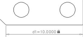
In a similar manner, you can add additional dimensional constraints to the rest of the bracket or convert existing dimensions (if you had some) via the Convert button in the Ribbon’s Parametric tab. Note the central idea behind this tool. The dimensional values are “locked in,” as represented by the lock graphic, and do not budge regardless of how other surrounding geometry may change.
13.6 Dimension-Driven Design
Let us put the preceding information together into a concise approach to design, as well as add in some comments about how to work smoothly with dimensional constraints. First of all, you can change the value of the dimensional constraint by just double-clicking on it and typing in something else (Figure 13.22).
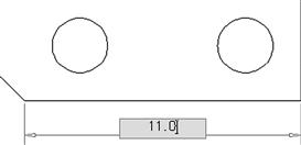
The value forces the line to move to the right, leaving a gap, which is not quite what you intended. Try the same with a circle and diameter constraint (Figure 13.23).

This leads to much better results; the circle has changed its size. There is a very important point to understand here in order to take full advantage of these tools. With linework and angles, dimensional constraints need to work together with geometric constraints. Used just by themselves, dimensional constraints change only the dimension value and drag the lines along for a ride; but if you add a coincident geometric constraint, the lines are “glued” together so you can make entire sections of the design properly constrained. A coincident constraint asks you to select one of the lines, then the second, and create a point where they intersect. Try this out on our bracket’s bottom pieces, and try changing the bottom line’s size again, leading to quite a different effect.
A lot more can be written about constraints in general; it is a broad and important topic. You are encouraged to explore further and practice setting up dimensional constraints on critical parts of a design. It will take some getting used to, and applying dimensional constraints intelligently can be awkward at first. The key is to apply these constraints only to the critical geometry and not constrain every single line and circle on the screen. Fortunately, AutoCAD prevents you from doing this and issues a warning that you are overconstraining or there are conflicts, similar to high-end solid modeling applications.
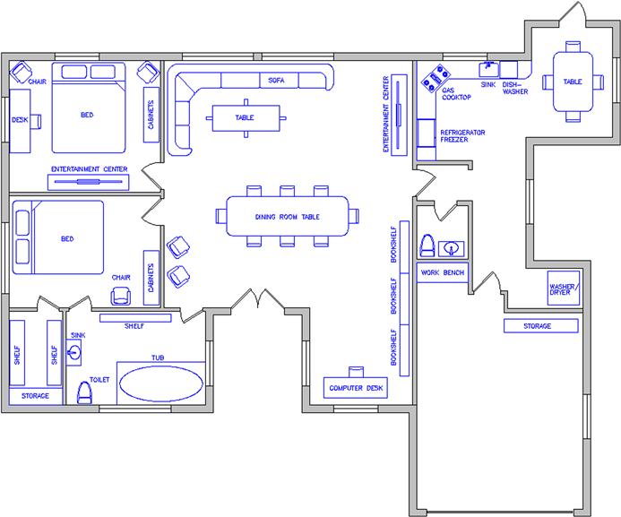
13.7 Level 2 Drawing Project (3 of 10): Architectural Floor Plan
For Part 3 of the drawing project, you complete the architectural/interior design by adding furniture and appliances to the house.
Step 1. You again need new layers:
Step 2. Dimensions for the furniture and appliances are not specifically given, but draw in reasonable-size designs, as seen in the layout. Feel free to add more than is shown. The full plan is in Figure 13.24. Your drawing features the colors listed in Step 1.
Step 3. Add in text describing the furniture and appliances. Put it on the text layer. It should take you about an hour to an hour and a half to add in the new features. Use copy often!
Summary
You should understand and know how to use the following concepts and commands before moving on to Chapter 14:
![]() Creating a new dim style (ddim)
Creating a new dim style (ddim)
![]() No permanent settings; but know functions of all
No permanent settings; but know functions of all
![]() Architectural tick setting; know functions of all others
Architectural tick setting; know functions of all others
![]() Text font and size settings; know functions of all others
Text font and size settings; know functions of all others
![]() Fit setting; know functions of all others
Fit setting; know functions of all others
![]() Zero suppression settings; know functions of all others
Zero suppression settings; know functions of all others
![]() Multiplier settings; know functions of all others
Multiplier settings; know functions of all others
Exercises
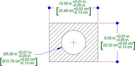
1. Draw the following shape and label it exactly as shown. Be sure to note all the modifications to the dimensions, including arrowheads and the presence of alternate units and tolerances. You may have to get creative with the leader. (Difficulty level: Intermediate; Time to completion: 10–15 minutes.)
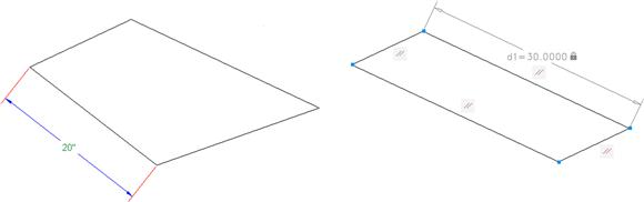
2. Draw a rough parallelogram shape, with one side 20″, as shown on the left. Parallel constrain all four sides, filleting if necessary. Then, carefully, coincident constrain all four corners. Finally, dimension constrain one side, using a value of 30 as seen on the right. If everything is done right, the rectangle should increase in size uniformly. (Difficulty level: Easy; Time to completion: 5 minutes.)