Surfaces and Meshes
Learning Objectives
In this chapter, we focus on surfaces instead of solid objects. These objects have no depth the way solids do but possess many desirable properties for design work. Specifically, we mention
By the end of the chapter, you will be able to create a variety of surfaces and meshes.
Estimated time for completion of chapter: 2 hours.
26.1 Introduction to Surfaces and Meshes
In this chapter, we explore some of AutoCAD’s surfacing and meshing capabilities. They underwent some significant enhancements in the AutoCAD 2011 release. A surface and a mesh are often the same, since in all but a few cases, a surface, by definition, is made up of a mesh. A mesh can then be described as an interconnecting weave of lines representing a surface (as opposed to a solid).
AutoCAD has several general approaches to creating, and working with, these objects. The most recent approach parallels what has been done in advanced 3D software like CATIA for some time now. You create a rough “blob” representing a general shape, then you adjust it one mesh at a time, pushing, pulling, and sculpting it like a piece of clay.
Another method involves creating a “framework” for the surface, a sort of skeleton, if you will. This framework is generally made using splines, which can be shaped easily via control points (grips). You can then create surfaces on top of this framework.
Finally, surfaces can be created via ordinary design methods already covered. Recall how you revolved an “open” profile to create a surface model in Chapter 24. In the same chapter, you also used the loft command to create surfaces between two arcs. Loft is actually quite a useful command for basic surfacing of noncomplex curvature.
We start from the beginning and cover “legacy” meshing capabilities. These tools, such as planar surface, region, and the “surf” family (rulesurf, tabsurf, revsurf, and edgesurf), have been around for quite some time and are useful for basic surfacing and meshing tasks. We then move on to some advanced legacy tools, such as 3D faces and meshes, and discuss the new family of tools introduced (or enhanced) in AutoCAD 2011. Remember, more than ever, these tools depend on your imagination and creativity to shine. They work best when combined by a skilled user to create some very advanced shapes.
26.2 Surfacing Commands
Planar Surface
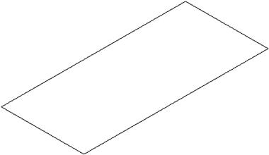
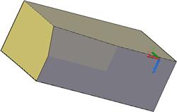
Perhaps the simplest thing you can surface is a rectangle, and this is where we start. While loft can accomplish this surfacing in theory, you need cross sections. Here, you just have a mundane shape and want to cover it with a surface, and a simpler command, called planar surface or just planesurf, is available. To try it out, switch to 3D and create a rectangle of any size, as seen in Figure 26.1.
We would like to add a simple surface to the rectangle without extruding or making it a true solid:
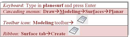
Step 1. Start the planesurf command via any of the preceding methods.
![]() AutoCAD says: Specify first corner or [Object]<Object>:
AutoCAD says: Specify first corner or [Object]<Object>:
Step 2. Using OSNAPs, select one of the corners of the rectangle.
![]() AutoCAD says: Specify other corner:
AutoCAD says: Specify other corner:
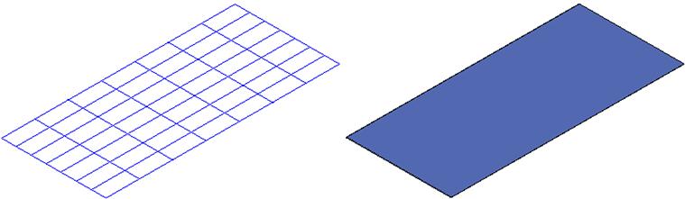
Step 3. Select the diagonally opposite corner of the rectangle. A surface is formed, as seen in the wireframe and shade modes in Figure 26.2.
You can also use planesurf to create surfaces out of objects by typing in o for Object. You can then just select the object and turn it into a surface; no clicking of points is needed. This is useful when a curvature, such as an arc, is involved and point-by-point clicking is not practical. Figure 26.3 shows a closed border drawn with a pline, with planesurf then applied in 3D.

Region
Region gets a brief mention here as an alternate method to create a simple surface. The difference here is that a region is a surface but not a mesh, a rare instance when this is the case. You are not able to edit it in any way, and that may be just fine for simple shapes. To try out region, create another rectangle or circle in 3D with shading on.
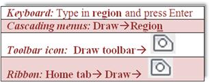
Step 1. Start the region command via any of the preceding methods.
Step 2. Pick your shape and press Enter.
A region is created.
Rulesurf
We now go over the family of “surfs.” These are all legacy commands that perform different varieties of surfacing, depending on the given starting conditions.
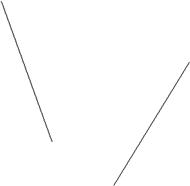
Rulesurf stands for “ruled surface” and is a handy tool to create surfaces between various straight lines or curves (without cross sections) that are not necessarily straight or parallel to each other or even closed. It fills a niche somewhere between the loft and planar surface options. To try it out, create two lines at a random angle to each other, as seen in Figure 26.4.

Step 1. Start the rulesurf command via any of the preceding methods.
Current wire frame density: SURFTAB1=6
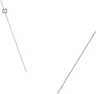
Step 2. Select the first line, as seen in Figure 26.5.
Step 3. Select the second line at roughly the same upper location (if you select a bottom location the surface self-intersects). The shaded results are shown in Figure 26.6.
As with many of these surfacing techniques, at first, the results may not seem very useful, but with some imagination and creativity, you can use them to fulfill rather complex surfacing needs. For example, in Figure 26.7, we create two arcs, rotate one of them 90°, and connect them end to end.
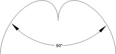
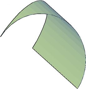
You can then apply rulesurf to these arcs and get a unique result as seen in Figure 26.8. The arcs became one surface. It is then shaded and rotated for a different view. The density of the mesh can be set by the SURFTAB1 and SURFTAB2 system variables by simply inputting a higher value.
Tabsurf
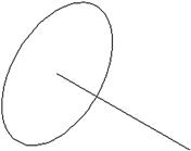
Tabsurf stands for “tabulated surface” and is a surfaces version of the extrude command, with some elements of path extrusion mixed in. The command requires a path curve and a direction vector. To try it out, create a circle with a perpendicular line, as seen in Figure 26.9.

Step 1. Start the tabsurf command via any of the preceding methods.
![]() AutoCAD says: Current wire frame density: SURFTAB1=50Select object for path curve:
AutoCAD says: Current wire frame density: SURFTAB1=50Select object for path curve:
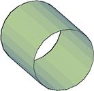
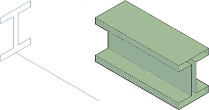
The result, shown in Figure 26.10, is a surface projected along the direction vector, not unlike path extrusion or regular extrude, with the difference, however, that the object is not a solid but a surface (be sure to set the SURFTAB1 and SURFTAB2 system variables to a high value for smoothness). A similar example with an I-beam is shown in Figure 26.11.
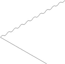
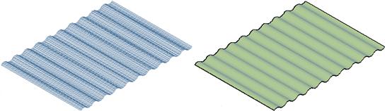
The final tabsurf example is slightly more complex. In 2D, you need to draw a string of connected arcs, all pedited together, as seen in Figure 26.12. Go into 3D and rotate the string of arcs into a straight up position if need be. Then, draw a perpendicular direction vector, attached to one end of the arc string, as seen in Figure 26.13, finally tabsurf the shape, as seen in Figure 26.14. These exercises should generate some ideas as far as applying the techniques to actual design work.
Revsurf
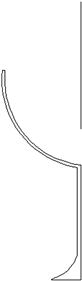
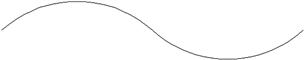
Revsurf stands for “revolved surface” and is a close relative of the revolve command covered in earlier 3D chapters, with the only difference in many cases being that revsurf produces somewhat smoother curves, if the SURFTAB1 and SURFTAB2 system variables are set high enough (around 50 is a good starting point). Generally, you can treat this command as an alternative to revolve. To illustrate it, create the profile seen in Figure 26.15; it is similar to the cup profile used with revolve. Be sure to pedit the profile.
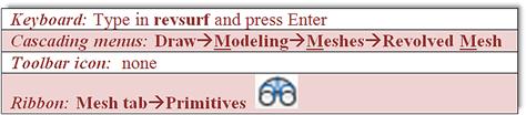
Step 1. Start the revsurf command via any of the preceding methods.
![]() AutoCAD says: Current wire frame density: SURFTAB1=50 SURFTAB2=6
AutoCAD says: Current wire frame density: SURFTAB1=50 SURFTAB2=6
![]() AutoCAD says: Select object that defines the axis of revolution:
AutoCAD says: Select object that defines the axis of revolution:
Step 3. Select the rotation axis (the vertical line).
![]() AutoCAD says: Specify start angle<0>:
AutoCAD says: Specify start angle<0>:
![]() AutoCAD says: Specify included angle (+=ccw,−=cw)<360>:
AutoCAD says: Specify included angle (+=ccw,−=cw)<360>:
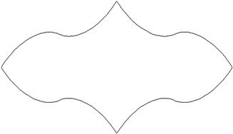
Step 5. Key in any value or press Enter for the full 360°. The result, shaded, is shown in Figure 26.16.

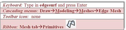
Edgesurf
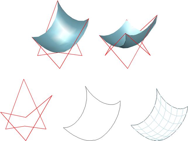
The edgesurf command creates a Coons surface patch mesh or a mesh in the M and N directions between a set of edges that are attached to each other with endpoints in a closed loop. The hard part is of course properly defining these edges. Once that is done correctly, AutoCAD fills in the rest and a sophisticated surface is created.
For a good mesh rendering, you need to make it dense, using the SURFTAB1 and SURFTAB2 system variables set to 50 or more (too much, though, slows down your system’s performance). Now, let us try to create a basic mesh as an example. In 2D, draw two arcs and pedit them as seen in Figure 26.17.
Now switch to 3D, and using the copy and rotate3D commands, arrange them in a closed loop, with each side 90° perpendicular to its neighbor, as seen in Figure 26.18.
Step 1. Start the edgesurf command via any of the preceding methods.
![]() AutoCAD says: Current wire frame density: SURFTAB1=50SURFTAB2=50
AutoCAD says: Current wire frame density: SURFTAB1=50SURFTAB2=50
Select object 1 for surface edge:
Step 2. Select the four edges, one after the other.
![]() AutoCAD says: Select object 2 for surface edge:
AutoCAD says: Select object 2 for surface edge:
Select object 3 for surface edge:
Select object 4 for surface edge:
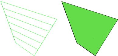
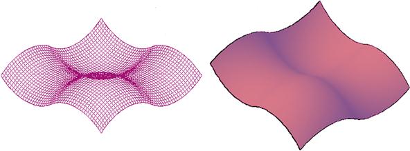
Step 3. After the final edge is selected, you see the mesh image shown on the left in Figure 26.19. On the right, it is shaded and slightly rotated for a better view.
Creating these meshes can be time consuming and occasionally troublesome, but if you follow the basic rules of pediting all the curves (edges) and connecting them together, you should be fine. The sophistication and versatility of this command is rather impressive, and almost any curve can be represented, if you can find a clever way to create the necessary edges. The only limitation is that you are limited to four edges at a time, but by connecting separate meshed objects together, you can get around this.
3Dface and 3Dmesh
Our final brief discussion on legacy mesh commands focuses on free-form meshes, ones that require no cross section profile or framework. However, just because the framework is not required, does not mean it is not necessary to a meaningful design. The 3Dface command is actually the one referred to in the chapter introduction as a way to dress up a “framework.” The idea is to simply click your way around points in the design, and when AutoCAD senses a closed path, it installs a surface.
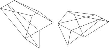
Let us give this a try on a random set of surfaces. The design shown in Figure 26.20 can be created by carefully rotating the UCS icon while drawing straight lines to establish a “skeleton” shape. Then, using grips, you can move the intersections of lines together to other intersections. Finally, you can add new lines by just drawing from endpoint to endpoint. Try to create a number of faces that can be filled in. Your shape need not look exactly like this one.
The command is activated via typing or a cascading menu.
Step 1. In 3D mode, with shading and Ortho on, type in 3dface and press Enter, or use the cascading menu Draw → Modeling → Meshes → 3D Face.
![]() AutoCAD says: 3dface Specify first point or [Invisible]:
AutoCAD says: 3dface Specify first point or [Invisible]:
Step 2. Using OSNAP endpoints, click around each facet of the shape. After each click,
![]() AutoCAD says: Specify second point or [Invisible]:
AutoCAD says: Specify second point or [Invisible]:
Specify third point or [Invisible]
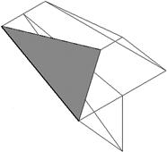
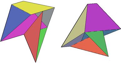
Step 3. After three or four clicks (depending on which facet you chose to do first), you should be able to get what is seen in Figure 26.21. Continue covering the other faces, and add color, to get what is shown in Figure 26.22 (viewed from several angles).
Little is said of 3Dmesh. This command is a good subject for programming and automation. The 3Dmesh command asks you for the size of the mesh in the M and N directions and location (vertex) points. These can be entered manually or as points on a framework. Using AutoLISP, a programmer can automate meshing of complex surfaces, but this is beyond the scope of the book.
The 3Dface and 3Dmesh commands conclude a basic overview of legacy commands, ones that have been available for years. A great many new mesh tools were introduced back in AutoCAD 2011, and we look at some here. These tools involve “sculpting” a shape, which is a popular way to create meshes in advanced 3D solid modeling software, as mentioned at the start of this chapter.
26.3 Smooth Mesh Primitives
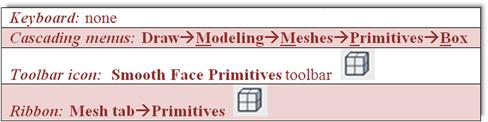
The way to start “sculpting” a shape is to first create one that has built-in mesh surfaces. This can be easily done via smooth mesh primitives. Primitives, as introduced in Chapter 23, are simple solid shapes, such as a box, sphere, and cone. You again create these shapes, but now they have mesh surfaces that can be manipulated into complex shapes. To create mesh primitives, you can use the Ribbon, the Smooth Mesh Primitives toolbar (Figure 26.23), or cascading menus, as seen in the command matrix:
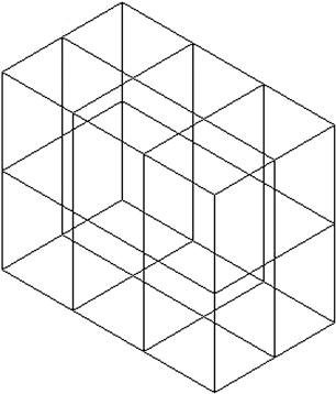
The steps to create the box are similar to the regular primitives box (review Chapter 23, if needed), but the results, viewed in wireframe, are definitely not the same, as seen in Figure 26.24.
The primitive is now composed of multiple faces that can be shaped and morphed into the desired final shape. You can alter the number of faces (technically called tessellation divisions) of the primitive via the Mesh Primitive Options dialog box (Figure 26.25). It can be accessed via the small arrow at the bottom right of the Ribbon’s Mesh → Primitives tab.
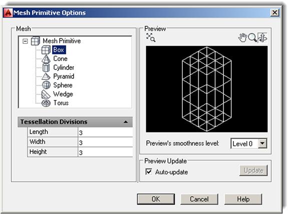
Select the shape with which you want to work and change the tessellation values, that is, length, width, or height, thereby creating more faces. Having more working surfaces on a shape yields smoother shapes and more “control points” with which to alter the meshes. It also allows for more accuracy in shaping the part. The trade-off is more complexity and possible introduction of errors, as well as an extra load on computing resources if the meshes are extremely dense.
How dense to make the mesh grip is a common engineering dilemma in finite element analysis (FEA) for stresses and loads and computational fluid dynamics (CFD) for fluid flow modeling. With modern computers, taxing the resources is less of an issue but can still be a problem if you add one too many digits to the density value. Since you may be working with individual mesh facets in this case, make the overall grid only as dense as you, the user, not the computer, can comfortably handle. This can also be automated via the mesh smoothing command, as described next.
Mesh Modification 1. Smoothness
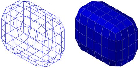
You can smooth out the primitive shapes automatically via the mesh smoothing command, best accessed via the Ribbon’s Mesh tab. Your choices are Smooth More (increases the number of facets in the mesh), Smooth Less (decreases the number of facets in the mesh), or Refine Mesh (same as Smooth More but works only after that command is employed). Take a few minutes to try out the results on the box. After one Smooth More, followed by a Refine Mesh, you get the modified version of the shape shown in Figure 26.26, as seen in wireframe and realistic visual style mode side by side. Notice the marked increase in facets.
Mesh Modification 2. Filters and Gizmos
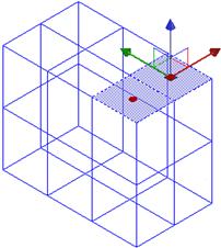
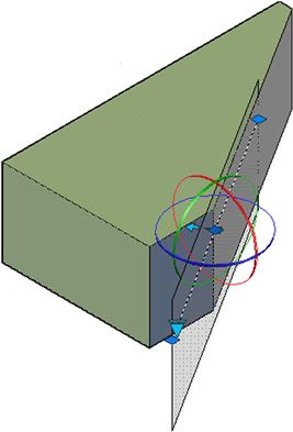
Return your shape to the original box via the undo command. Next, we explore the face filter and the move and rotate gizmo (first seen in Chapter 22). From Mesh tab → Subobject, select Move Gizmo followed by Face Filter. Then, click on the top right two facets, as seen in Figure 26.27.
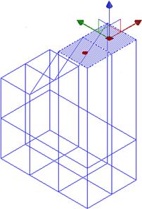
The mesh facets are highlighted and the move gizmo appears. With the UCS icon aligned vertically and Ortho on, move the facets up, noticing how the entire shape is “morphed,” as seen in Figure 26.28.
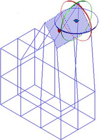
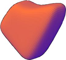
In a similar manner, select the rotate gizmo and rotate the facets to a different angle, as seen in Figure 26.29. After a few rounds of adding smoothness and another shading change, the shape is presented in Conceptual Visual Style (Figure 26.30).
Mesh Modification 3. Additional Tools
Using smoothness, filters, and gizmos, you can already do quite a bit of shape morphing. Here are some additional tools to consider:
![]() Collapse Face or Edge: This tool, found under the Ribbon’s Mesh → Mesh Edit, makes a selected face or edge disappear on a shape, with the remaining ones closing ranks around the void, as seen in Figure 26.31 with a mesh box.
Collapse Face or Edge: This tool, found under the Ribbon’s Mesh → Mesh Edit, makes a selected face or edge disappear on a shape, with the remaining ones closing ranks around the void, as seen in Figure 26.31 with a mesh box.
![]() Convert to Solid or Surface: This tool, found under the Ribbon’s Mesh → Convert Mesh, converts mesh objects to solids or surfaces. You do not see a tremendous difference in appearance, but the shape is editable in a different way from an organic mesh. For example, individual facets can no longer be selected in a solid.
Convert to Solid or Surface: This tool, found under the Ribbon’s Mesh → Convert Mesh, converts mesh objects to solids or surfaces. You do not see a tremendous difference in appearance, but the shape is editable in a different way from an organic mesh. For example, individual facets can no longer be selected in a solid.
![]() Section Plane: This tool, found under the Ribbon’s Mesh → Section, allows you to easily section a mesh shape to view the interior or just a piece of it. This tool can be used on regular solids as well. Simply press Section Plane and select a method of locating the plane. The result of sectioning a simple box is shown in Figure 26.32. The section itself can be rotated via the gizmo.
Section Plane: This tool, found under the Ribbon’s Mesh → Section, allows you to easily section a mesh shape to view the interior or just a piece of it. This tool can be used on regular solids as well. Simply press Section Plane and select a method of locating the plane. The result of sectioning a simple box is shown in Figure 26.32. The section itself can be rotated via the gizmo.
Summary
You should understand and know how to use the following concepts and commands before moving on to Chapter 27:
Exercise
1. Based on what you learned of 3D design and the edgesurf command, create the mesh chair that follows (shown from two angles). You need to create a frame in 3D space, attach arcs in strategic locations, and finally execute the edgesurf command for the mesh. A visual step-by-step breakdown is shown for clarity, but you still need to figure out the steps involved. One possible approach is to draw a wireframe 3D box (not a solid) and use that as a reference point to attach the frame. (Difficulty level: Advanced; Time to completion: 30 minutes.)