Lighting and Rendering
Learning Objectives
In this final chapter, we explore lighting and rendering and discuss
By the end of the chapter, you will be able to add various lighting effects and basic materials to your design.
Estimated time for completion of chapter: 2 hours.
30.1 Introduction to Lighting and Rendering
This final chapter of the textbook is dedicated to “finishing” a design. This means the application of lighting, shadows, environmental effects, backgrounds, materials, and rendering. It is something that is done last, after a design is completed, as these effects do not stand alone but are applied to an existing model. All finishing effects are loosely grouped under two major categories: lighting and rendering.
It should be stated up front that, despite major improvements in AutoCAD’s lighting and rendering ability, it is still not quite on par with available dedicated rendering software. Packages such as Form Z, Rhino, and the famous 3 ds Max (3D Studio Max) can create stunning photorealistic images and, in some cases, advanced animation. Autodesk has had a bit of a dilemma with AutoCAD. Should it pursue advanced rendering development and risk taking sales away from its own 3 ds Max or add to AutoCAD to please those few customers who may need some rendering ability? After all, the vast majority of AutoCAD designs are still plain old 2D schematics or floor plans, and it makes little sense to load AutoCAD with rendering power that customers rarely need.
The answer is somewhere in the middle. AutoCAD always had limited lighting and rendering ability, going back to the Advanced Modeling Extension of the early releases, and slowly new features were added. These were just enough to satisfy casual 3D users but never so much that they stopped considering the expensive dedicated software. One way around this, of course, is to purchase reasonably priced add-ons, like AccuRender (see Appendix I). This software adds dramatically to the existing capabilities without expensive investment.
In the meantime, AutoCAD’s development team (always in need of new features to advertise as a new version rolls out) slowly but surely kept improving the built-in lighting and rendering. Today, with the latest version, Release 2014, we have quite a bit to discuss. It is still not 3 ds Max, but if you have never worked with advanced dedicated effects software, you may be impressed. It is also a great introduction into that world. Let us take a look first at lighting and related topics (such as Shadows and Sun and Sky), followed by materials and rendering.
30.2 Lighting
Lighting in digital art and CAD software is based on several established techniques and principles, and AutoCAD is no exception. A model can be lit in one of several ways, which involve variations on ambient, directional, or spotlight light sources. This, of course, mimics our everyday experiences, where we have a variety of lighting conditions, from diffused sunlight to the intense headlights of a car and everything in between.
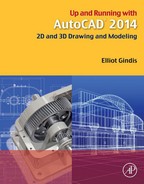
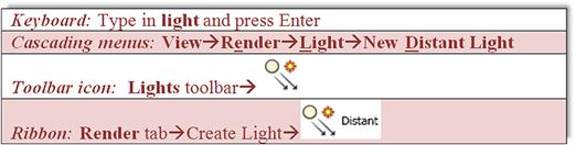
Most of the options that have to do with lighting are either on the Lights toolbar or the Render tab of the Ribbon. Both are shown in Figure 30.1.
The three main options for lighting are:
![]() Point light: This light, similar to a light bulb, originates from one point and radiates in all directions.
Point light: This light, similar to a light bulb, originates from one point and radiates in all directions.
![]() Spotlight: This light, similar to a flashlight, originates from one point, but radiates in only one direction.
Spotlight: This light, similar to a flashlight, originates from one point, but radiates in only one direction.
![]() Distant light: This light, similar to the sun, originates from a distant source and does not fall off in intensity.
Distant light: This light, similar to the sun, originates from a distant source and does not fall off in intensity.
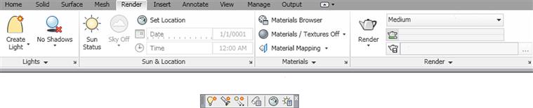
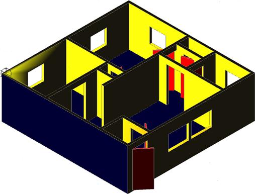
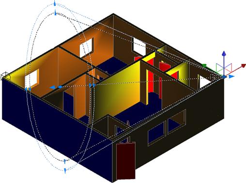
Let us give these various lights a try. Bring up the same 3D apartment model used in the previous chapter and switch to the Realistic Visual Style (RVS), as seen in Figure 30.2.
Point Light
We can now try to set a lighting condition and look over some of the available options, which are relatively similar from one lighting scenario to another. The one most often used is the New Point Light option, described here.
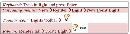
Step 1. Begin the New Point Light via any of the preceding methods. You may see a warning dialog box, asking if you want to turn off default lighting (not shown here). Go ahead and agree to that.
Step 2a. If you type in light,
![]() AutoCAD says: Enter light type [Point/Spot/Web/Targetpoint/Freespot/freeweB/Distant]<Point>:
AutoCAD says: Enter light type [Point/Spot/Web/Targetpoint/Freespot/freeweB/Distant]<Point>:
Go ahead and select P for Point and press Enter. Go on to Step 2b.
Step 2b. If you used any of the other methods or just did Step 2a,
![]() AutoCAD says: Specify source location<0,0,0>:
AutoCAD says: Specify source location<0,0,0>:
Step 3. Select the extreme upper left corner of the building.
![]() AutoCAD says: Enter an option to change [Name/Intensity factor/Status/Photometry/shadoW/Attenuation/filterColor/eXit]<eXit>:
AutoCAD says: Enter an option to change [Name/Intensity factor/Status/Photometry/shadoW/Attenuation/filterColor/eXit]<eXit>:
Step 4. We go over some of these options in detail momentarily, but for now press i for Intensity.
![]() AutoCAD says: Enter intensity (0.00−max float)<1.0000>:
AutoCAD says: Enter intensity (0.00−max float)<1.0000>:
Step 5. Enter the value 20. Then, press c for Color.
![]() AutoCAD says: Enter true color (R,G,B) or enter an option [Index color/Hsl/colorBook]<255,255,255>:
AutoCAD says: Enter true color (R,G,B) or enter an option [Index color/Hsl/colorBook]<255,255,255>:
Step 6. Press i for Index color and enter color number 30 (it is one of the yellows).
The result is a spotlight located at an upper left corner of the 3D model (notice the circular marker), shining yellow light on the entire structure (Figure 30.3). Note that the light goes through the walls, illuminating everything equally, as if the walls are not even there. We change this later with the LIGHTINGUNITS system variable. You can locate as many point lights as you want; we only do one example of this.
So, what options can you change to enhance this very basic example? Let us go over them, as they appear in the other light choices as well—Name, Intensity factor, Status, Photometry (if LIGHTINGUNITS is set to 1 or 2 only), shadoW, Attenuation, filterColor, eXit:
![]() Name: You can give the light setting a name so you know to what you are referring later on. Use logical names like Bedroom Spotlight 1.
Name: You can give the light setting a name so you know to what you are referring later on. Use logical names like Bedroom Spotlight 1.
![]() Intensity factor: This is the brightness of the light; you can enter almost any value. The exact number is dictated by design needs and often arrived at by trial and error.
Intensity factor: This is the brightness of the light; you can enter almost any value. The exact number is dictated by design needs and often arrived at by trial and error.
![]() Status: This simply means on or off. You can position a light then turn it off, as with a regular light switch, if not needed in a scenario.
Status: This simply means on or off. You can position a light then turn it off, as with a regular light switch, if not needed in a scenario.
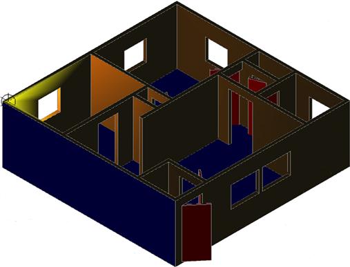
![]() Photometry: This option depends on the LIGHTINGUNITS system variable, to be set to 1 or 2 (International or American with Photometry enabled), not 0, which is Generic lighting, as seen in Figure 30.3. Once that is set, photometry refers to the perceived power emitted by a light source. The result of setting that system variable is that a more realistic light gradient is shown, where the intensity fades as you move farther from the lamp source, as seen in Figure 30.4. The three options under Photometry are:
Photometry: This option depends on the LIGHTINGUNITS system variable, to be set to 1 or 2 (International or American with Photometry enabled), not 0, which is Generic lighting, as seen in Figure 30.3. Once that is set, photometry refers to the perceived power emitted by a light source. The result of setting that system variable is that a more realistic light gradient is shown, where the intensity fades as you move farther from the lamp source, as seen in Figure 30.4. The three options under Photometry are:
![]() Intensity: This is similar to the previous generic intensity setting, but allows for more options. The default values are in Candelas (Cd), the SI unit of luminous intensity. You can also press f for the Flux option (Lm) or press i for Illuminate, in which case you can use Lux (Lx) or Foot Candle (Fc) values. As a suboption, you can even use Distance. These settings are familiar to any architect or designer who works with lighting. Photometry is a science unto itself; experiment with the various options, and if you have never worked with lighting before, seek out information online or in a library on this interesting topic.
Intensity: This is similar to the previous generic intensity setting, but allows for more options. The default values are in Candelas (Cd), the SI unit of luminous intensity. You can also press f for the Flux option (Lm) or press i for Illuminate, in which case you can use Lux (Lx) or Foot Candle (Fc) values. As a suboption, you can even use Distance. These settings are familiar to any architect or designer who works with lighting. Photometry is a science unto itself; experiment with the various options, and if you have never worked with lighting before, seek out information online or in a library on this interesting topic.
![]() Color: This option assigns color to the light (otherwise, it is the default white) but works differently from the color filters in the main menu. Here, color represents a type of lamp or a Kelvin temperature setting. If you type in a question mark and press Enter twice you get this list of standard colors or lamps:
Color: This option assigns color to the light (otherwise, it is the default white) but works differently from the color filters in the main menu. Here, color represents a type of lamp or a Kelvin temperature setting. If you type in a question mark and press Enter twice you get this list of standard colors or lamps:
You can choose a lamp type and it is shown. Another interesting option is the ability to use temperature as a light setting. Type in k for Kelvin and enter a temperature value. As mentioned before, it takes experience and knowledge to use these tools properly, and there is a science of proper lighting. For those who work in this field, AutoCAD gives some basic tools with which to work, and for those who do not, this is an invitation to learn more.
![]() eXit. This option exits the Photometry command.
eXit. This option exits the Photometry command.
![]() shadoW. This command controls the appearances of shadows when your light source encounters an obstruction (such as a piece of furniture). The options are:
shadoW. This command controls the appearances of shadows when your light source encounters an obstruction (such as a piece of furniture). The options are:
![]() Off. This option turns off shadows.
Off. This option turns off shadows.
![]() Sharp. This displays shadows with sharp edges (less realistic but better computer performance).
Sharp. This displays shadows with sharp edges (less realistic but better computer performance).
![]() soFtmapped. This entire option has to do with soft shadows and how much computer resources (map size and memory) to allocate to the shadow. As with all such settings, there is a trade-off between quality and system performance.
soFtmapped. This entire option has to do with soft shadows and how much computer resources (map size and memory) to allocate to the shadow. As with all such settings, there is a trade-off between quality and system performance.
![]() softsAmpled. This is another set of settings for realistic shadows.
softsAmpled. This is another set of settings for realistic shadows.
![]() Attenuation. Attenuation (with AutoCAD anyway) is the decay of light as distance from the source increases. There are a variety of settings here, such as:
Attenuation. Attenuation (with AutoCAD anyway) is the decay of light as distance from the source increases. There are a variety of settings here, such as:
![]() attenuation Type. The two choices are Inverse Linear and Inverse Squared, which have to do with the strength of the light (whether the value is squared or linear) as the distance increases.
attenuation Type. The two choices are Inverse Linear and Inverse Squared, which have to do with the strength of the light (whether the value is squared or linear) as the distance increases.
![]() Use limits. This option turns limits (see later) on and off.
Use limits. This option turns limits (see later) on and off.
![]() attenuation start Limit. This option specifies where the light starts.
attenuation start Limit. This option specifies where the light starts.
![]() attenuation End limit. This option specifies where the light ends.
attenuation End limit. This option specifies where the light ends.
![]() eXit. This option exits the attenuation command.
eXit. This option exits the attenuation command.
![]() filterColor. This is simply the color of the light emitted with no regard to temperature or type of lamp, as seen with Photometry settings. You can enter RGB values, Index colors, or use any of the other color choices AutoCAD provides.
filterColor. This is simply the color of the light emitted with no regard to temperature or type of lamp, as seen with Photometry settings. You can enter RGB values, Index colors, or use any of the other color choices AutoCAD provides.
Spotlight
Now that you have had an introduction to these tools, let us briefly go over the remainder of the lights and a few other associated options. The New Spotlight option is roughly similar in theory to the New Point Light option just covered.
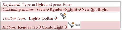
Step 1. Begin the Spotlight via any of the preceding methods. You may see a warning dialog box, asking if you want to turn off default lighting (not shown here). Go ahead and agree to that.
Step 2a. If you type in light,
![]() AutoCAD says: Enter light type [Point/Spot/Web/Targetpoint/Freespot/freeweB/Distant]<Point>:
AutoCAD says: Enter light type [Point/Spot/Web/Targetpoint/Freespot/freeweB/Distant]<Point>:
Go ahead and select S for Spot and press Enter. Go on to Step 2b.
Step 2b. If you used any of the other methods or just did Step 2a,
![]() AutoCAD says: Specify source location<0,0,0>:
AutoCAD says: Specify source location<0,0,0>:
Step 3. Select a corner of the building (a flashlight is attached to the crosshairs).
![]() AutoCAD says: Specify target location<0,0,−10>:
AutoCAD says: Specify target location<0,0,−10>:
Step 4. Select a point in such a way as to indicate a direction for the spotlight to shine. A large menu appears that has essentially the same choices seen previously.
![]() AutoCAD says: Enter an option to change [Name/Intensity factor/Status/Photometry/Hotspot/Falloff/shadoW/Attenuation/filterColor/eXit]<eXit>:
AutoCAD says: Enter an option to change [Name/Intensity factor/Status/Photometry/Hotspot/Falloff/shadoW/Attenuation/filterColor/eXit]<eXit>:
There are however some new commands in this menu, as described next:
![]() Hotspot: This command specifies the angle that defines the brightest cone of light, which is known as the beam angle. This value can range from 0° to 160°.
Hotspot: This command specifies the angle that defines the brightest cone of light, which is known as the beam angle. This value can range from 0° to 160°.
![]() Falloff: This command specifies the angle that defines the full cone of light, which is also known as the field angle. This value can range from 0° to 160°.
Falloff: This command specifies the angle that defines the full cone of light, which is also known as the field angle. This value can range from 0° to 160°.
Step 5. Using values of 100 for the Intensity factor and 255,127,0 for the filterColor, go ahead and adjust those options.
Figure 30.5 shows the results. The spotlight is attached to the right corner of the design. It is clicked on to show its light cone (called a glyph) and grips. These glyphs can be adjusted via the grips to vary the “sweep” of the light source and the area it affects (illuminates).
Distant Light
The final light type we try out is called New Distant Light. This is more of a floodlight that saturates everything and is not used as often.
Step 1. Begin the Distant Light via any of the preceding methods. You may see a warning dialog box asking if you want to disable distant lights when the lighting unit is photometric (not shown here). Allow it in this case!
Step 2a. If you type in light,
![]() AutoCAD says: Enter light type [Point/Spot/Web/Targetpoint/Freespot/freeweB/Distant]<Point>:
AutoCAD says: Enter light type [Point/Spot/Web/Targetpoint/Freespot/freeweB/Distant]<Point>:
Go ahead and select d for Distant and press Enter. Go on to Step 2b.
Step 2b. If you used any of the other methods or just did Step 2a,
![]() AutoCAD says: Specify light direction FROM<0,0,0>or [Vector]:
AutoCAD says: Specify light direction FROM<0,0,0>or [Vector]:
Step 3. Pick a direction from which the light comes.
![]() AutoCAD says: Specify light direction TO<1,1,1>:
AutoCAD says: Specify light direction TO<1,1,1>:
Step 4. Pick a direction into which the light goes. The familiar menu appears (not shown this time), and you can set some options to complete the distant light setting.
To complete our tour of AutoCAD’s lighting features, there are a few more items to cover. Perhaps the most important one is the Properties palette as it applies to lighting. Double-click on any light to call it up, as seen with the spotlight in Figure 30.6.
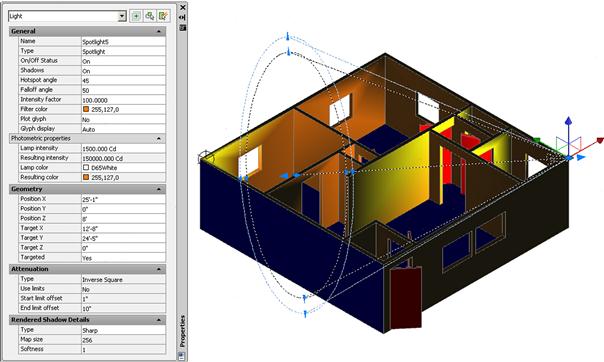
Using the Properties palette you can change virtually any aspect of the newly created light, with the added benefit that you can see the effect right away.
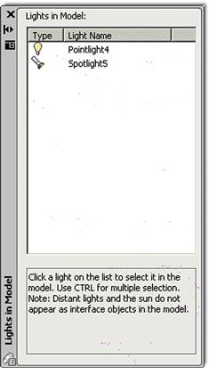
To keep track of all your lights, you can activate the Lights in Model palette (Figure 30.7) by clicking on the Lights List icon on the toolbar or the arrow flyout on the Ribbon’s Render tab. This palette shows every light created, which is why it is important to give them descriptive names. In our example, we did not, and they are simply referred to as Pointlight4 and Spotlight5.
Shadows, Sun, and Sky
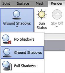
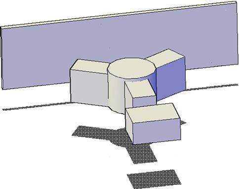
Shadows are an integral part of the sun and sky settings, which are nothing more than shadows customized to a specific location and time. You can get a simple shadow right away, however. Draw and position some simple 3D shapes, and in the Ribbon’s Render tab, find the shadow settings and select Ground Shadows (Figure 30.8). The result is seen in Figure 30.9.
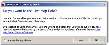
Sun and Sky, as mentioned already, refer to a background light setting where you can set a particular city location anywhere in the world and its particular latitude and longitude are factored into the lighting conditions. To set the time zone, you need access to Live Map Data through Autodesk 360. If you have this, then press the Set Location drop-down icon in the Render, Sun & Location tab (it looks like a globe) and select From Map. A pop-up box (Figure 30.10) then asks you if you want to use Live Map Data. If you say Yes, you will be prompted to sign into Autodesk 360. Note that you can also import maps via the*.kml or *.kmz files if you have used those before.
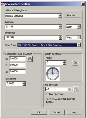
Finally, note that this is brand new for AutoCAD 2014. Prior to that, in AutoCAD 2013 and older versions, you could have just picked to enter the location values and seen the dialog box shown in Figure 30.11. It is reproduced here in case you end up working on an older release. The Geographic Location dialog box allows you to set your particular region, country, or city via drop-down menus. You can use the provided time zones as an alternative. You can also click anywhere on the map or enter values manually, although not too many people have that kind of information handy. When done, click on OK.
Finally, let us bring up sun properties via the final icon on the Lights toolbar. The Sun Properties palette appears, as seen in Figure 30.12.
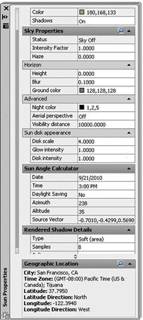
Using this palette and a bit of trial and error (at least until you understand what each property does), you can set the ambient sunlight properties. The exact description of each category is found in the Help files, reproduced here for convenience and in edited form for clarity.
General: This is where you set the general properties of the sun.
![]() Status: This option turns the sun on and off. If lighting is not enabled in the drawing, this setting has no effect.
Status: This option turns the sun on and off. If lighting is not enabled in the drawing, this setting has no effect.
![]() Intensity Factor: This option sets the intensity or brightness of the sun. The range is from 0 (no light) to maximum. The higher is the number, the brighter the light.
Intensity Factor: This option sets the intensity or brightness of the sun. The range is from 0 (no light) to maximum. The higher is the number, the brighter the light.
![]() Color: This option controls the color of the light. Enter a color name or number or click on Select Color to open the Select Color dialog box.
Color: This option controls the color of the light. Enter a color name or number or click on Select Color to open the Select Color dialog box.
![]() Shadows: This option turns on and off the display and calculation of shadows for the sun. Turning shadows off increases performance.
Shadows: This option turns on and off the display and calculation of shadows for the sun. Turning shadows off increases performance.
Sky Properties: This is where you set the general properties of the sky.
![]() Status: This option determines if the sky illumination is computed at render time. This has no impact on the viewport illumination or the background. It simply makes the sky available as a gathered light source for rendering. Note: This does not control the background. Its values are Sky Off, Sky Background, and Illumination.
Status: This option determines if the sky illumination is computed at render time. This has no impact on the viewport illumination or the background. It simply makes the sky available as a gathered light source for rendering. Note: This does not control the background. Its values are Sky Off, Sky Background, and Illumination.
![]() Intensity Factor: This option provides a way to magnify the effect of the sky light. Its values are 0.0 to MAX.
Intensity Factor: This option provides a way to magnify the effect of the sky light. Its values are 0.0 to MAX.
![]() Haze: This option determines the magnitude of scattering effects in the atmosphere. Its values are 0.0 to 15.
Haze: This option determines the magnitude of scattering effects in the atmosphere. Its values are 0.0 to 15.
Horizon: This category of properties pertains to the appearance and location of the ground plane.
![]() Height: This option determines the absolute position of the ground plane relative to world zero. This parameter represents a world-space length and should be formatted in the current length unit. Its values are+to MAX.
Height: This option determines the absolute position of the ground plane relative to world zero. This parameter represents a world-space length and should be formatted in the current length unit. Its values are+to MAX.
![]() Blur: This option determines the amount of blurring between ground plane and sky. Its values are 0 to 10.
Blur: This option determines the amount of blurring between ground plane and sky. Its values are 0 to 10.
![]() Ground Color: This option determines the color of the ground plane by selecting a color from the drop-down list. You can also select the Select Color dialog box to make a color choice.
Ground Color: This option determines the color of the ground plane by selecting a color from the drop-down list. You can also select the Select Color dialog box to make a color choice.
Advanced: This category of properties adds various artistic effects.
![]() Night Color: This option specifies the color of the night sky by selecting a color from the drop-down list. You can also select the Select Color dialog box to make a color choice.
Night Color: This option specifies the color of the night sky by selecting a color from the drop-down list. You can also select the Select Color dialog box to make a color choice.
![]() Aerial Perspective: This option specifies if aerial perspective is applied. Its values are On or Off.
Aerial Perspective: This option specifies if aerial perspective is applied. Its values are On or Off.
![]() Visibility Distance: This option specifies the distance at which 10% haze occlusion results. Its values are 0.0 to MAX.
Visibility Distance: This option specifies the distance at which 10% haze occlusion results. Its values are 0.0 to MAX.
Sun Disk Appearance: This category of properties pertains to the background only, and they control the appearance of the sun disk.
![]() Disk Scale: This option specifies the scale of the sun disk (1.0=correct size).
Disk Scale: This option specifies the scale of the sun disk (1.0=correct size).
![]() Glow Intensity: This option specifies the intensity of the sun glow. Its values are 0.0 to 25.0.
Glow Intensity: This option specifies the intensity of the sun glow. Its values are 0.0 to 25.0.
![]() Disk Intensity: This option specifies the intensity of the sun disk. Its values are 0.0 to 25.0.
Disk Intensity: This option specifies the intensity of the sun disk. Its values are 0.0 to 25.0.
Sun Angle Calculator: This category of properties sets the angle of the sun.
![]() Date: This option displays the current date setting.
Date: This option displays the current date setting.
![]() Time: This option displays the current time setting.
Time: This option displays the current time setting.
![]() Daylight Saving: This option displays the current setting for daylight savings time.
Daylight Saving: This option displays the current setting for daylight savings time.
![]() Azimuth: This option displays the azimuth, the angle of the sun along the horizon clockwise from due north. This setting is read-only.
Azimuth: This option displays the azimuth, the angle of the sun along the horizon clockwise from due north. This setting is read-only.
![]() Altitude: This option displays the altitude, the angle of the sun vertically from the horizon. The maximum is 90°, or directly overhead. This setting is read-only.
Altitude: This option displays the altitude, the angle of the sun vertically from the horizon. The maximum is 90°, or directly overhead. This setting is read-only.
![]() Source Vector: This option displays the coordinates of the source vector, the direction of the sun. This setting is read-only.
Source Vector: This option displays the coordinates of the source vector, the direction of the sun. This setting is read-only.
Rendered Shadow Details: This category of properties specifies the properties of the shadows.
![]() Type: This option displays the setting for shadow type. This setting is read-only when the display of shadows is turned off. The selections are Sharp and Soft (mapped), which display the Map size option, and Soft (area), which displays the Samples option. Soft (area) is the only option for the sun in photometric workflow (LIGHTINGUNITS set to 1 or 2).
Type: This option displays the setting for shadow type. This setting is read-only when the display of shadows is turned off. The selections are Sharp and Soft (mapped), which display the Map size option, and Soft (area), which displays the Samples option. Soft (area) is the only option for the sun in photometric workflow (LIGHTINGUNITS set to 1 or 2).
![]() Map size (Standard lighting workflow only): This option displays the size of the shadow map. This setting is read-only when the display of shadows is turned off. Its values are 0 to 1000.
Map size (Standard lighting workflow only): This option displays the size of the shadow map. This setting is read-only when the display of shadows is turned off. Its values are 0 to 1000.
![]() Samples: This option specifies the number of samples to take on the solar disk. This setting is read-only when the display of shadows is turned off. Its values are 0 to 1000.
Samples: This option specifies the number of samples to take on the solar disk. This setting is read-only when the display of shadows is turned off. Its values are 0 to 1000.
![]() Softness: This option displays the setting for the appearance of the edges of shadows. This setting is read-only when the display of shadows is turned off. Its values are 0 to 50.0.
Softness: This option displays the setting for the appearance of the edges of shadows. This setting is read-only when the display of shadows is turned off. Its values are 0 to 50.0.
Geographic Location: This category of properties displays the current geographic location settings. This information is read-only. When a city is not stored with latitude and longitude, the city does not appear in the list. Use the Edit Geographic Location button to open the Geographic Location dialog box.
30.3 Materials and Rendering
Rendering in AutoCAD is a two-part story. The first part involves materials and simply adding them to designs. AutoCAD has a sizable built-in library of materials, with most residing in the tool palettes; and adding them is simply a matter of click and drag onto the design. These materials are pictures, usually bitmaps, and they simply cover the design similar to wallpaper. You can also create and modify your own materials, within limits.
The other side to rendering is actual rendering, where more advanced settings are applied and the software makes passes over the design, rendering the surfaces as desired. In regard to both material application and rendering, other dedicated software packages have far more capabilities than AutoCAD, as explained earlier in the chapter, but this is still a good introduction to this fascinating world. And, remember that quality of output is often a result of knowledge. An expert using limited software may still achieve better results than a novice on superior software. If you wish to pursue this type of work further, consult Appendix I for some additional information on this topic.
Materials
Let us jump right into materials by introducing the two relevant palettes (materials is very much a palette-driven feature): the Materials Browser and the Materials Editor. Both are shown in Figure 30.13 and can be accessed via the cascading menus: Tools→Palettes→Materials Browser (or Materials Editor).
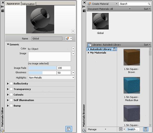
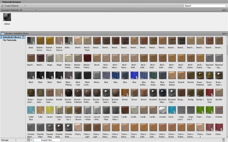
Let us first take a look at the Materials Browser. It was expanded significantly over the last several releases of AutoCAD and now features over 1200 materials (see Figure 30.14). These materials are bitmap graphics designed in-house at Autodesk (or acquired) and are superimposed onto geometry in a simple manner, akin to wrapping paper. They are not “procedural materials” and do not become one with the design (see Appendix I for more on this). The Materials Browser allows you to visually search the materials database and create a library of materials relevant to your design intent.
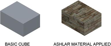
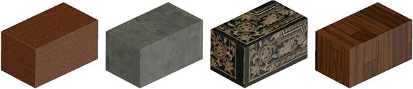
Applying these materials without further modification is simply a matter of click and drag. Draw a cube of any size, as seen in Figure 30.15, and select a random material. Then, click and drag the material onto the cube, which acquires those properties instantly. Some additional examples are shown in Figure 30.16.
If you right-click on any of the materials in the selection list, you can add it to the Material Browser’s My Materials collection for future reuse. These materials can be deleted and renamed, if necessary. The main Autodesk library, however, is locked, as indicated by a padlock. You can sort My Materials (or the main library) according to Name, Category, Type, or Color as well as filter what is shown by All, Applied, Selected, or Unused. Spend some time getting acquainted with the Materials Browser, so you have a good idea of what is available and what you can do with these materials.
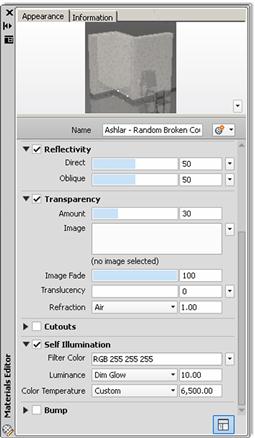
The Materials Editor is exactly that: It edits and modifies existing materials. To enter something into the editor, click on a material once in the browser (but do not drag it anywhere). The material appears in the editor’s preview window, with associated menus below that. An example is shown with the previously used Ashlar material (Figure 30.17). Some of the more useful settings that can be modified include Reflectivity, Transparency, and Self Illumination. Explore all these settings to see what the effects are. When done, the material appears in the Materials Browser. Be sure to rename it before using.
Rendering
Our final discussion involves rendering. Because of AutoCAD’s improved materials and excellent visualization and coloring options, rendering in general is not something you often require, and your options here are not exactly extensive. In advanced modeling software, rendering is a general catch-all term that refers to advanced colorizing, materials, and lighting effects applied to a design. In AutoCAD, these procedures are separate from a rendering, and we have already covered them in this chapter or elsewhere. What rendering means in our discussion is simply a processed output that can be saved to a file. You still have to add colors, materials, and lighting prior to a render. Then, the process of rendering an image produces a tangible output in the form of a jpg, or another format such as a bmp (bitmap) or a tiff, that can be printed on a LaserJet (for example). These renderings can then be inserted into a presentation or given to a client.
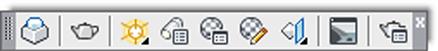
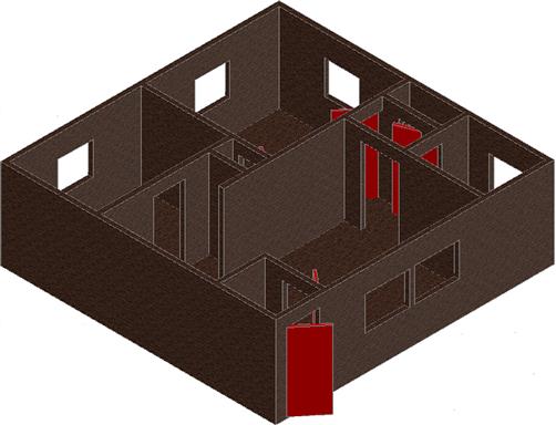
The gateway to rendering is the Render toolbar (Figure 30.18) or the Ribbon’s Render tab. Let us give this a try and render our familiar apartment (Figure 30.19), introducing features as needed. Bring up the design and add a new material for some variety, as shown in the figure.
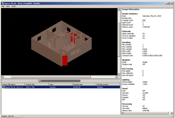
Let us jump right in and render the design without changing any settings. We will return and tweak things right afterward. Click on the Render icon (the teapot); you can also just type in render and press Enter. The render panel appears and the apartment is rendered in several seconds. When done, information about the rendering process is shown to the right and below the rendered model (Figure 30.20).
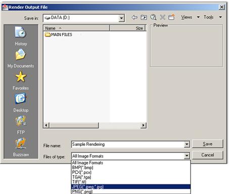
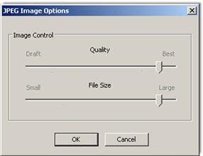
The next step is to output the design to one of several formats. Select File→Save… and the Render Output File dialog box appears (Figure 30.21). Select the output format, jpeg in this case, and give it a name and location. Once you press Save, the JPEG Image Options dialog box appears (Figure 30.22). Adjust the settings if desired and press OK. The image is saved to the previously selected location, ready for printing or insertion into a presentation.
We conclude rendering with a brief survey of rendering settings, in case you want to deviate from the basic procedure just outlined. The Settings palette is accessed via the Advanced Render Settings… icon or the flyout arrow on the bottom right of the Ribbon’s Render tab. It is shown in Figure 30.23.
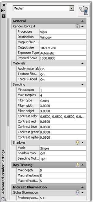
Review the settings on your own or with the Help files, as there is quite a bit here. Some of the more relevant ones (reading top to bottom) are the options that allow you to render only a small section of the image if needed via Procedure, control resolution via Output Size, and Apply Materials to determine what type of view gets rendered. You can also do all this via the Ribbon; just drop down the Render arrow on the Render tab.
Summary
You should understand and know how to use the following concepts and commands at the conclusion of this chapter:
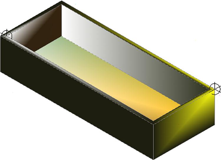
Exercise
1. Create the following 20"×50" box, extruded to 10" and shelled out to 1". Attach a point light to both corners. Set one point light to an intensity of 100 and a blue color. Set the other to an intensity of 75 and a red color. Then, render the figure to a jpg file. (Difficulty level: Easy; Time to completion: 5–10 minutes.)