Custom Linetypes and Hatch Patterns
Appendix D outlines how to create custom linetypes and hatch patterns, if such a need arises.
This appendix outlines the basic procedures for creating custom linetypes and hatch patterns if you need something that is not found in AutoCAD itself or with any third party vendor. All linetypes and hatch patterns were originally “coded” by hand, and there is nothing inherently special or magical about making them; they just take some time and patience to create. Though it is admittedly rare for a designer to need something that is not already available, creating these entities is a good skill to acquire. We just present the basics here, and you can certainly do additional research and come up with some fancy designs and patterns.
Linetype Definitions (Basic)
All linetypes in AutoCAD (about 38 standard ones, to be precise) reside in the acad.lin or the acadiso.lin file. These are linetype definition files that AutoCAD accesses when you tell it to load linetypes into a drawing. In AutoCAD 2014, these files can be found in the AutodeskAutoCAD_2014_English_Win_32bit_dlmx86en-usacadAcadProgram FilesRootUserDataCacheen-usSupport folder. Anything you do to these files, including adding to them, immediately shows up the next time you use linetypes. Our goal here is to open up the acad.lin file, analyze how linetypes are defined, then make our own.
Locate and open (usually with Notepad) the acad.lin file and take a look at it closely. Here is a reproduction of the first six linetype definitions: Border (Standard, 2, and X2) and Center (Standard, 2, and X2).
*BORDER,Border____ .____ .____ .____ .____ .
A,.5,2.25,.5,2.25,0,2.25
*BORDER2,Border (.5x)__.__.__.__.__.__.__.__.__.__.__.
A,.25,-.125,.25,2.125,0,2.125
*BORDERX2,Border (2x)________ .________ .___
A,1.0,2.5,1.0,2.5,0,2.5
*CENTER,Center_____________________________
A,1.25,-.25,.25,-.25
*CENTER2,Center (.5x)_______________________
A,.75,2.125,.125,2.125
*CENTERX2,Center (2x)_________________________
A,2.5,2.5,.5,2.5
Let us take just one linetype and look at it closer. Here is the standard size center line:
*CENTER,Center_____________________________
A,1.25,2.25,.25,2.25
The two lines you see are the header line and the pattern line; both are needed to properly define a linetype. The header line consists of an asterisk, followed by the name of the linetype (CENTER), then a comma, and finally the description of the linetype (Center). In this case, they are the same.
The pattern line is where the linetype is actually described, and the cryptic-looking “numerical code” (A,1.25,2.25,.25,2.25) is the method used to describe it and needs to be discussed for it to make sense.
The A is the alignment field specification and is of little concern (AutoCAD accepts only this type so you always see A). Next are the linetype specification numbers, and they actually describe the linetype using dashes, dots, and spaces. Let us go over them, as really this is the key concept.
The basic elements are
Now, you just have to mix and match and arrange these in the order you want them to be to define a linetype you envisioned.
What would the following look like?
(A,.75,-.25,0,-.25,.75)
Well, you know that dashes are positive, so everywhere you see .75, there will be a dash of that length. Spaces are negative, so everywhere you see 2.25, there will be a space of that length, and finally a 0 is a dot. This is the result:
___ .___
These are the essentials of creating basic linetypes. AutoCAD, however, also allows for two other types to be created, and they are part of the complex linetype family: string complex and shape complex.
Linetypes (String Complex and Shape Complex)
The problem with the previously mentioned linetypes is obvious; you have only dashes, dots, and spaces with which to work. While this is actually enough for many applications, you may occasionally (especially in civil engineering and architecture) need to draw boundary or utility lines that feature text (Fence line, Gas line, etc.) or you may want to put small symbols between the dashes. It is here that strings and shapes come in.
String complex linetypes allow you to insert text into the line. Here is a gas line example:
*GAS_LINE,Gas line ----GAS----GAS----GAS----GAS----GAS----GAS—
A,.5,-.2,[“GAS”,STANDARD,S=.1,R=0.0,X=20.1,Y=2.05],2.25
The header line is as discussed before, and the pattern line still starts with an A. After the A, we see a dash of length .5 followed by a space of length .2; so far it is familiar. Next is information inside a set of brackets, defined as follows:
[“String”, Text Style, Text Height (S), Rotation (R), X-Offset (X), Y-Offset (Y)].
Finally, there is a .25 space and the string repeats. The meaning of the information inside the brackets is as follows:
![]() String: This is the actual text, in quotation marks (GAS, in our example).
String: This is the actual text, in quotation marks (GAS, in our example).
![]() Text Style: The predefined text style (STANDARD, in our example).
Text Style: The predefined text style (STANDARD, in our example).
![]() Text Height: The actual text height (.1, in our example).
Text Height: The actual text height (.1, in our example).
![]() Rotation: The rotation of the text relative to the line (0.0, in our example).
Rotation: The rotation of the text relative to the line (0.0, in our example).
![]() X-Offset: The distance between the end of the dash and the beginning of the text as well as the end of the text and the beginning of the dash (a space of .1, in our example).
X-Offset: The distance between the end of the dash and the beginning of the text as well as the end of the text and the beginning of the dash (a space of .1, in our example).
![]() Y-Offset: The distance between the bottom of the text and the line itself. This function centers the text on the line.
Y-Offset: The distance between the bottom of the text and the line itself. This function centers the text on the line.
With these tools you can create any text string linetype.
Shape complex linetypes are basically similar, aside from one difference: Instead of a text string, we have a shape definition inserted. Shape definitions are a separate topic in their own right and are not covered in detail in this textbook. Briefly, however, shape files are descriptions of geometric shapes (such as rectangles or circles but can be more complex) and are written using a Text Editor and compiled using the compile command. They are saved under the *.shp extension. AutoCAD accesses these when it reads the linetype definitions. If you are familiar with shapes, then you can proceed in defining shape complex linetypes as with string complex ones.
Hatch Pattern Definitions (Basic)
Knowing the basics of linetype definitions puts you on familiar ground when learning hatch pattern definitions. Even though they are more complex, the basics and styles of description are similar.
Hatch pattern definitions are found in the acad.pat and acadiso.pat files, and they reside in the same folder as the .lin files. Open the acad.pat file and take a look at a few definitions. Some of them can get long and involved due to the complexity of the pattern (Gravel, for example), but Figure D.1 shows a simpler one to use as a first example: Honeycomb.
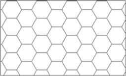
The pattern definition file that describes it looks like this:
*HONEY, Honeycomb pattern
0, 0,0, .1875,.108253175, .125,2.25
120, 0,0, .1875,.108253175, .125,2.25
60, 0,0, .1875,.108253175, 2.25,.125
The first line (header line) is as discussed previously with linetypes. The next three lines are the hatch descriptors, and they have somewhat different definitions as shown next:
Angle, X-Origin, Y-Origin, D1, D2, Dash Length
where (in this particular example),
![]() Angle: Angle of the pattern’s first hatch line from the X axis (0°, in our example).
Angle: Angle of the pattern’s first hatch line from the X axis (0°, in our example).
![]() X-Origin: X coordinate of hatch line (0,0, in our example).
X-Origin: X coordinate of hatch line (0,0, in our example).
![]() Y-Origin: Y coordinate of hatch line (.1875, in our example).
Y-Origin: Y coordinate of hatch line (.1875, in our example).
![]() D1: The displacement of second line (.1083, in our example).
D1: The displacement of second line (.1083, in our example).
![]() D2: The distance between adjoining lines (.125, in our example).
D2: The distance between adjoining lines (.125, in our example).
The pattern is repeated two more times to form the overall shape and repeated many more times in the overall hatch pattern.