
6. Manage Shapes
In This Chapter
• What are Groups, and why should I use them?
• How can I line my shapes up with Align?
• How does the Position feature make sure my shapes are not too close together?
• Will I get a Light Cycle if I enable Grid?
• How do I slip new shapes under old ones?
• How will Re-Layout Page fix my diagram?
Chapter 5, “Working with Shapes,” considered the ways you can select the shapes you want to use in your drawings. It also examined how you create your own collections of shapes and arrange them into stencil sets. In this chapter you start working with shapes placed into the drawing window. You look at fundamental tools like Groups and examine other tools and settings that allow you to keep things neatly arranged in your diagram.
Left to themselves, shapes can become unruly and difficult to position. They do not always have uniform shapes, and sometimes shapes overlap on a complex diagram. Although it would be nice to blame everything on shapes, Visio users contribute to the chaos—they work fast, deadlines must be met, and they can toss shapes into their drawing like nobody’s business. Visio’s creators want users to succeed in creating organized, structured, and polished looking diagrams. This chapter looks at the tools that help make this happen.
Using Groups to Organize Shapes
Groups have long been a feature in Visio, and they continue to be useful when you’re working with shapes. You might initially relate this concept with how you group pictures or files in other applications as a way of interacting with two or more shapes and allowing you to move or modify the properties of the group all at once. Although that is a valid way of grouping shapes in Visio, grouping shapes in Visio has even more robust uses.
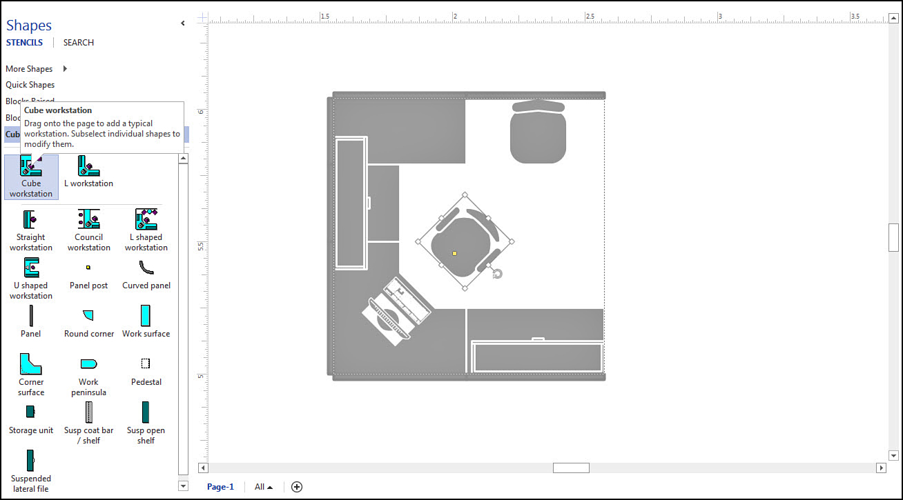
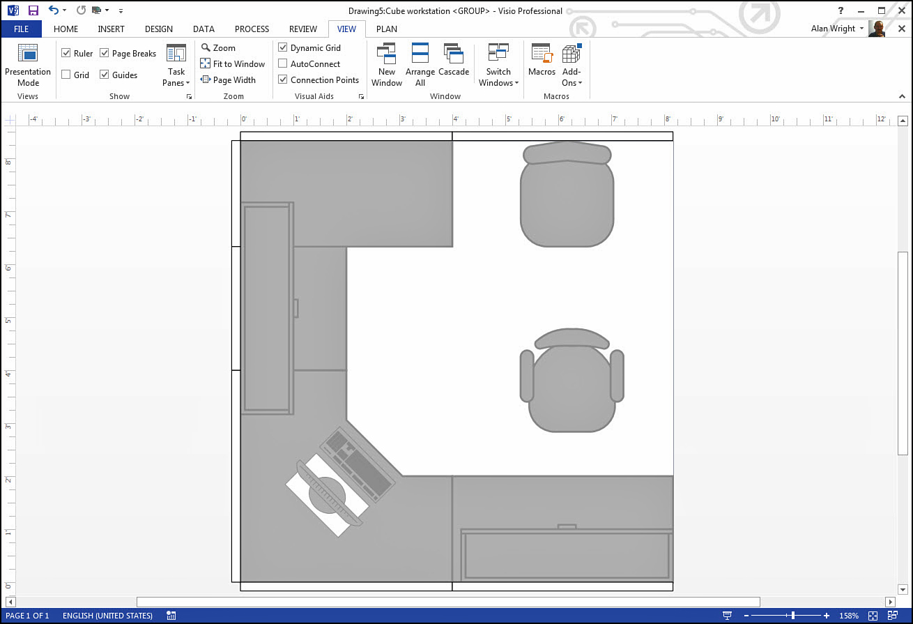
If you look through some of the templates in Visio, you may notice a few shapes that were created from grouped shapes. For example, check out Figure 6.1 where a Cube workstation shape was dropped onto a drawing. Hovering over the shape in the Shapes pane reveals the option to subselect individual shapes; in fact, you see a chair is selected in the drawing.
 Note
Note
Many shapes are simply grouped shapes that were combined to create common master shapes. By design, you do not have the option to subselect the individual shapes. An example is the PC shape mentioned in the following exercise. If you ungroup one of these shapes, you can then subselect the shapes. This is not something you would likely ever need to do for practical reasons, but it helps illustrate the nature and power of grouping.
Although grouping can be done with abandon, ungrouping should come with the severest of warnings when dealing with existing shapes. When shapes are grouped, a new shape is created, and the existing shapes are made subordinate to the new shape. There is no problem ungrouping at this point, but most shape designers add properties to this new shape and references from the subordinate shapes to this new shape. Ungrouping at this point deletes the new information and breaks the references. The correct way is to subselect and then edit the subordinate shapes. However, this is getting into an area beyond the scope of this book.
When to Use Groups
Groups should be used whenever you need to work with a combination of shapes as a unit, as was done in the case of the cubicle in Figure 6.1. Groups can save you time when applying common colors or other properties, and they are practical when you need to move or rotate multiple shapes. Groups can be formed as a temporary collection until certain changes are performed, and then a group can be ungrouped.
You can create a group using a current typical desk as a model.
1. Open a new Office Layout template.
2. From the Office Furniture stencil, select a desk and drag it to the drawing window. Select and drag a chair, and place it in front of the desk.
3. From the Office Equipment stencil, select a PC and place it on your desk.
4. Locate a nice plant from the Office Accessories stencil and place it by your desk. Go ahead and add a trash can as well.
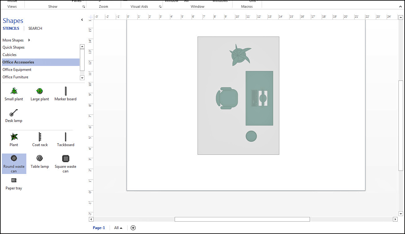
5. As shown in Figure 6.2, use your mouse to click and drag to select all these shapes. After selecting the shapes, you will see a temporary group with each individual shape boldly highlighted because they are still individual shapes.
6. Select the Home tab, and in the Arrange section select Group and then select Group again from the drop-down menu. The bold highlight goes away, and you are left with one selection area. Press Esc or click outside of the area and then click a shape in the desk area. The entire group is selected again.
7. Drag the group and notice that when all shapes move, they maintain their orientation.
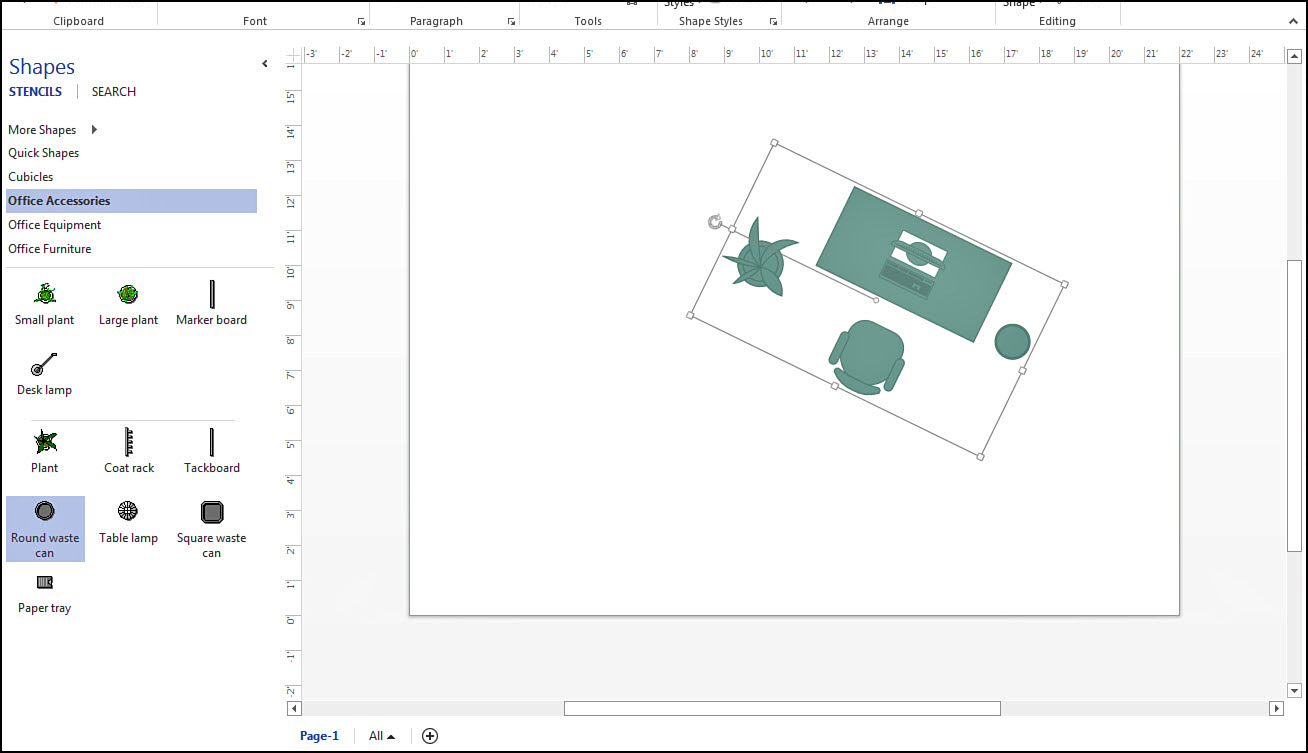
8. Select the Rotate handle for the group and drag it clockwise. The entire group rotates (see Figure 6.3).
9. Select the group, and click again to subselect your plant shape. Notice the group has a dashed outline, and the plant shape provides handles to move, resize, and rotate apart from the other group shapes.
10. Grab the selected plant shape and drag to a location outside of the outlined group. Click somewhere outside of the selected area to remove the selection fields.
11. Select the desk group and drag to a new location. Notice in Figure 6.4 that the plant shape is still part of the group, even though it is located outside of the group box.
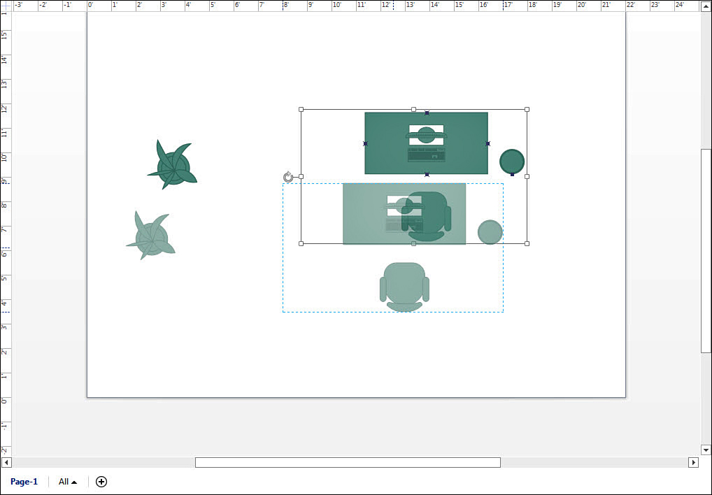
FIGURE 6.4 This plant shape is still tethered to its group. Until it is removed from the group, it is subject to changes made to the group.
12. Select the plant shape. From the Home tab, select Group, and then select Remove from Group. The plant has been removed, but the rest of the desk group is unchanged.
13. Select the desk group and right-click. Select Group and then select Ungroup from the right-click menu. The shapes are now ungrouped shapes as they were in Step 5.
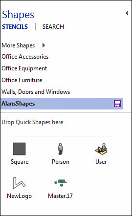
Groups are versatile, and as you experiment you see how intuitive it is to add and remove shapes. You may want to create a specific group and use it in the future. A grouped set of shapes can be added to a custom stencil. In Figure 6.5 you can see the Master.17 grouped shape was added to the stencil named AlansShapes. It is even possible using advanced techniques to have a grouped shape with all the needed shapes and connectors be designed to ungroup automatically when dropped into the drawing window.
 Tip
Tip
When you have selected multiple shapes that you want to group, press CTRL+G. To ungroup press CTRL+Shift+U.
When It Is Better to Avoid Groups
Whereas groups allow you to perform movement-oriented tasks on multiple shapes and form complex master shapes, there are times when groups are not a good choice. If you use groups to organize shapes, consider the more advanced alternatives to organizing shapes discussed in the sidebar “Organizing Shapes with Layers and Containers” earlier in this chapter.
In large diagrams, groups that span areas of a drawing may cause confusion when overlapping shapes that are not part of that group. Some complex shapes have shape data, which may be difficult to access when the shape is grouped. Awareness of how to subselect shapes and work with them may be a factor if you plan to collaborate on a drawing.
Editing Groups
When you work with a selected group shape, you have an additional tool for fine-tuning and editing. Right-click and select Group; then select Open Group to open the group window. As you see in Figure 6.6, this group window zooms in on the group contents. In this view you can subselect and tweak your group contents and even add content to the group. To save the changes, click the Close button.
Arranging Shapes
The importance of arrangement can be critical in some diagrams, such as a hierarchal Org chart. Visio provides many tools to help you adjust the way shapes and connectors are laid out in your drawings, and with the Live Preview feature, it takes a lot of the guesswork out of using these tools. Most of the tools are located on the Home tab, but there are a couple useful tools that affect layout on the Design and View tabs.
Figure 6.7 has shapes just strewn about. As the tools in this section are described you will see a few ways that order can be brought to this mess.
Using the Dynamic Grid
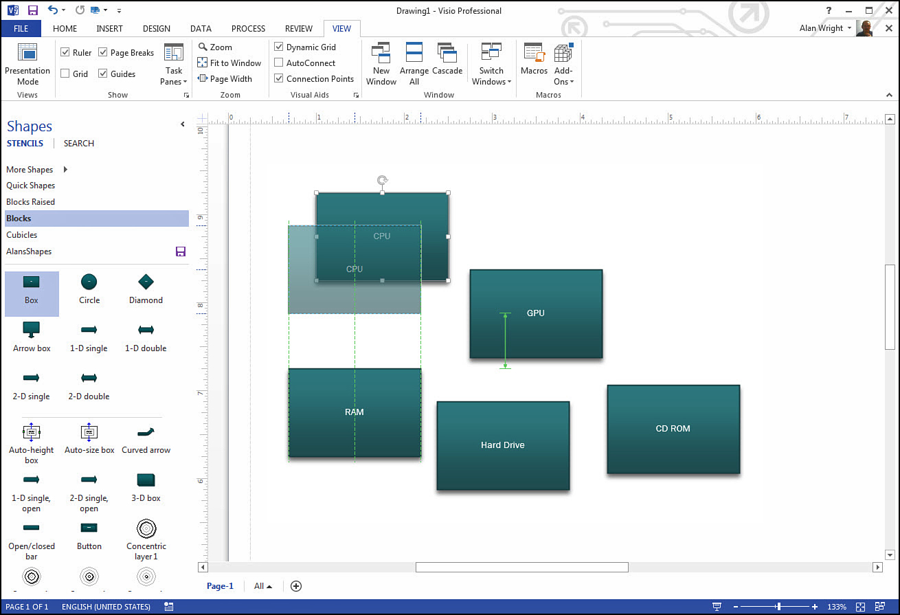
Dynamic Grid is a useful tool that you will likely leave enabled. This tool provides reference layout information that helps control placement of your shapes on-the-fly. Visual cues appear when you move shapes, as shown in Figure 6.7. Notice how the CPU shape is aligned with the RAM shape below it. Also, the spacing matches a standard spacing for these two shapes.
This Dynamic Grid tool is enabled on the View tab, in the Visual Aids section. Notice the check box is enabled in Figure 6.7. Without this feature you would be guessing at how closely these shapes lined up.
Change Spacing
Spacing is really a dynamic setting that is often determined by the initial placement of shapes. If you place two shapes on a drawing, Visio tries to use that spacing as a gauge for the next shape you drop. If you have shapes arranged in a cluster and then locate another cluster elsewhere in the drawing, Visio treats these as separate dynamic grids. The goal of the Dynamic Grid tool is to maintain a uniform appearance.
How to Align Shapes on the Grid
As shown in Figure 6.7, similar shapes can be arranged using distance and center line references. When the shapes are dissimilar, Visio still works to provide points of reference. Figure 6.8 shows a center line; by shifting the pentagon to the left or right, the edges will be lined up. A spacing indicator appears, based on the horizontal spacing I established with the rectangles.
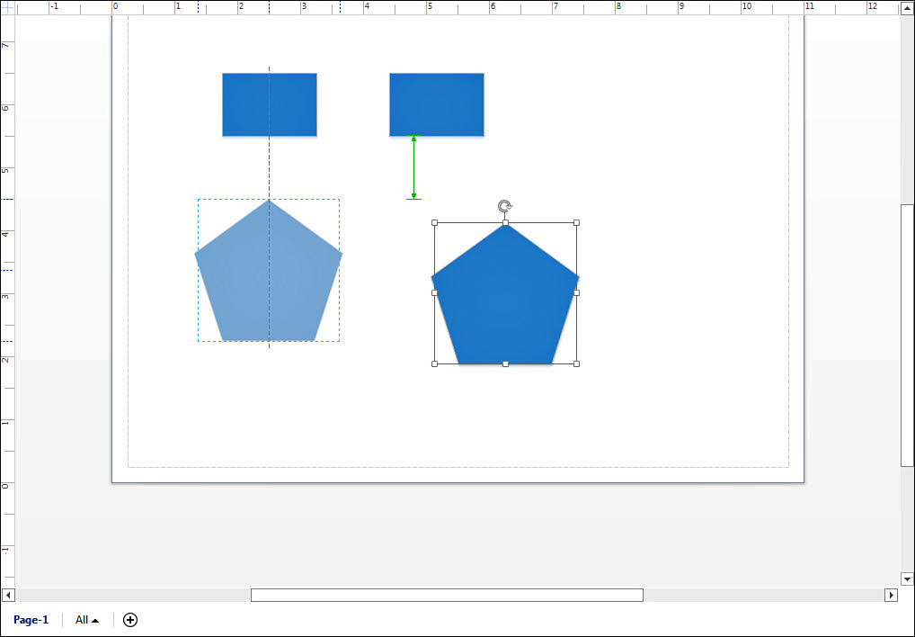
FIGURE 6.8 Visio provides visual cues to help place shapes with some sense of arrangement using the Dynamic Grid tool.
Straighten Up Shapes with Auto Align
The Home tab has a tool section labeled Arrange. The first main drop-downs provide powerful tools to quickly adjust your page. Selecting Align and Auto Align attempts to straighten the paths for connectors by aligning shapes on an entire page if nothing is selected. The tools under Align are more useful when working with selected shapes; in fact, most are grayed out until you select one or more shapes.
Align provides the following options for aligning the selected shapes:
• Auto Align moves selected shapes so that the shapes are all arranged at right angles with no concern for spacing. This allows connectors to have straight paths. The focus is on lining up the center axis of the selected shapes. The presence of connectors influences how much Auto Align moves the shapes. Notice in Figure 6.9 how orientation is similar to Figure 6.7; however, the five selected shapes are now aligned with one another.
• Align Left slides all shapes horizontally until they have the same left-side alignment as the first shape selected.
• Align Center moves shapes horizontally until the vertical axis is matched to the first selected shape (see Figure 6.10).
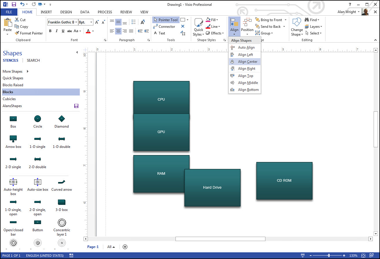
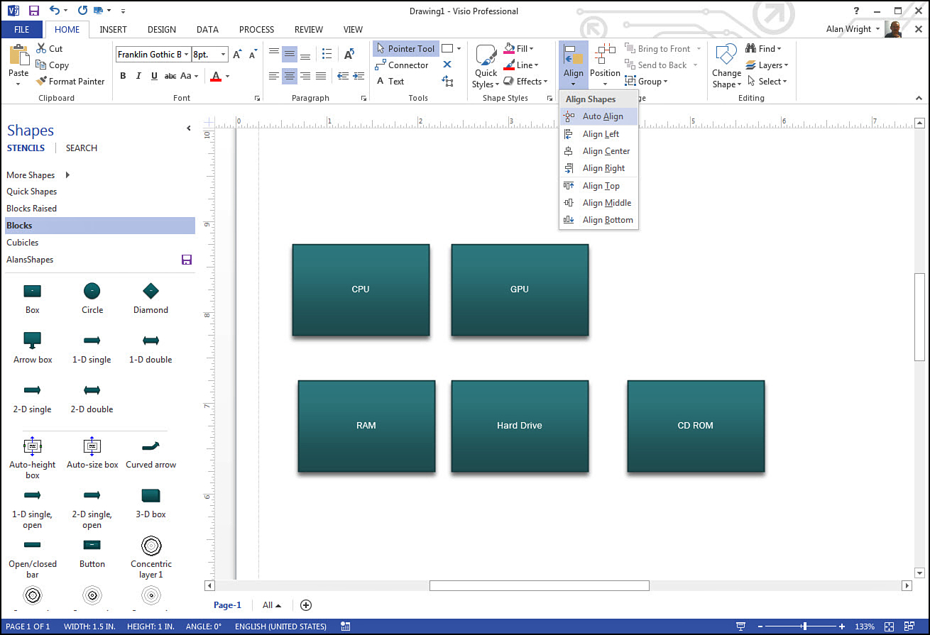
FIGURE 6.10 Align provides many ways to align selected shapes. Here, three selected shapes from Figure 6.7 are aligned using Align Center.
• Align Right moves selected shapes horizontally to match the right plane of the first selected shape.
• Align Top moves selected shapes vertically to match the top alignment of the first selected shape.
• Align Middle moves selected shapes vertically to match the center or middle alignment of the first selected shape.
• Align Bottom moves selected shapes vertically to match the bottom alignment of the first selected shape.
Note
Align creates overlaps if the focus is solely to align selected shapes vertically or horizontally. Also when working with multiple shapes, Align focuses on the first selected shape. This is recognized by a slightly bolder outline than the rest of the shapes. Hold the Shift or Ctrl key while you select shapes to control the order of selection.
Using Position to Arrange the Diagram
The second drop-down button in the Arrange section of the Home tab is labeled Position. This is home to many tools that focus on spacing between shapes.
• Auto Space moves selected shapes until the minimum spacing requirements are met between the selected shapes. It can be a little unpredictable when you work with selected shapes; sometimes Auto Space moves the entire group. With nothing selected, it adjusts the spacing between all items on the page to provide a minimum spacing.
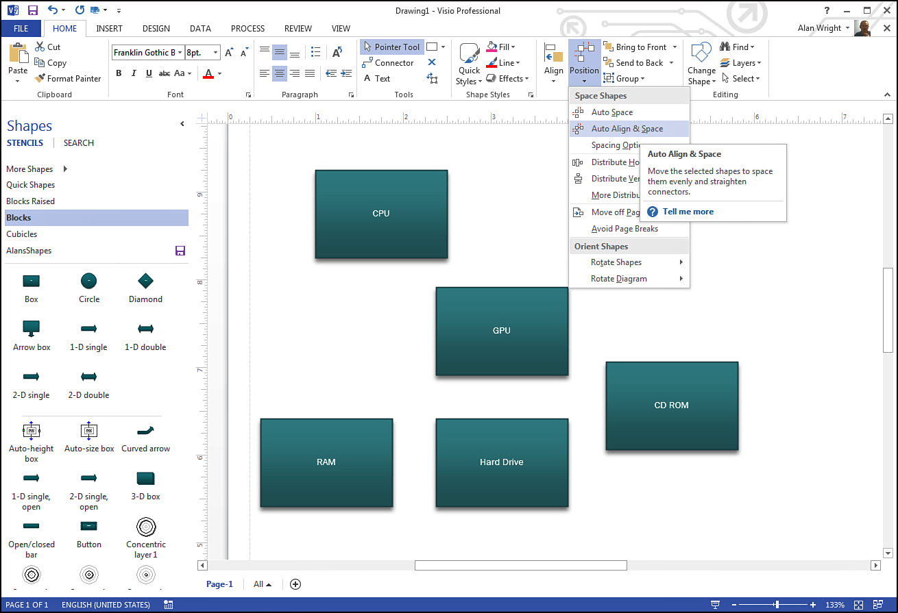
• Auto Align & Space combines the Auto Align and Auto Space. Shapes are neatly aligned, and the spacing between shapes is uniform. Although live preview doesn’t show which shapes are selected, Figure 6.11 has only GPU, RAM, and Hard Drive selected, and they are the only shapes aligned and spaced on the page. Notice the Tell Me More Link that opens additional information for these tools in a Visio Help window.
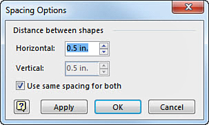
• Spacing Options opens a dialog box labeled Spacing Options where you can set the spacing (see Figure 6.12). The default in the U.S. is .5 inches, whereas Metric is 7.5mm.
Distributing Shapes
There are a few commands related to Distribute under the Position button on the Home tab. You may not immediately see how these tools can assist you with your diagram; however, recall the horizontal and vertical reference lines used for alignment in your shapes. Those guidelines are the focus of these tools.
• Distribute Horizontally moves your shapes so that the center lines are equidistantly spread out on the page.
• Distribute Vertically does the same using the middle line as a reference.
• More Distribute Options opens a window labeled Distribute Shapes (see Figure 6.13). This allows you to spread shapes out using left, right, top, and bottom reference points, as well as to spread the spacing horizontally or vertically.
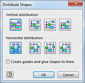
FIGURE 6.13 Distribute Shapes provides additional ways to spread shapes evenly across your drawings.
One practical way the Distribute tools are used is to establish reference points for diagrams. For example, think of the vertical and horizontal numbers and letters common on many maps. Distribute and Align tools can make quick work of setting up these kinds of professional reference points on a plan or diagram.
Rotating Shapes
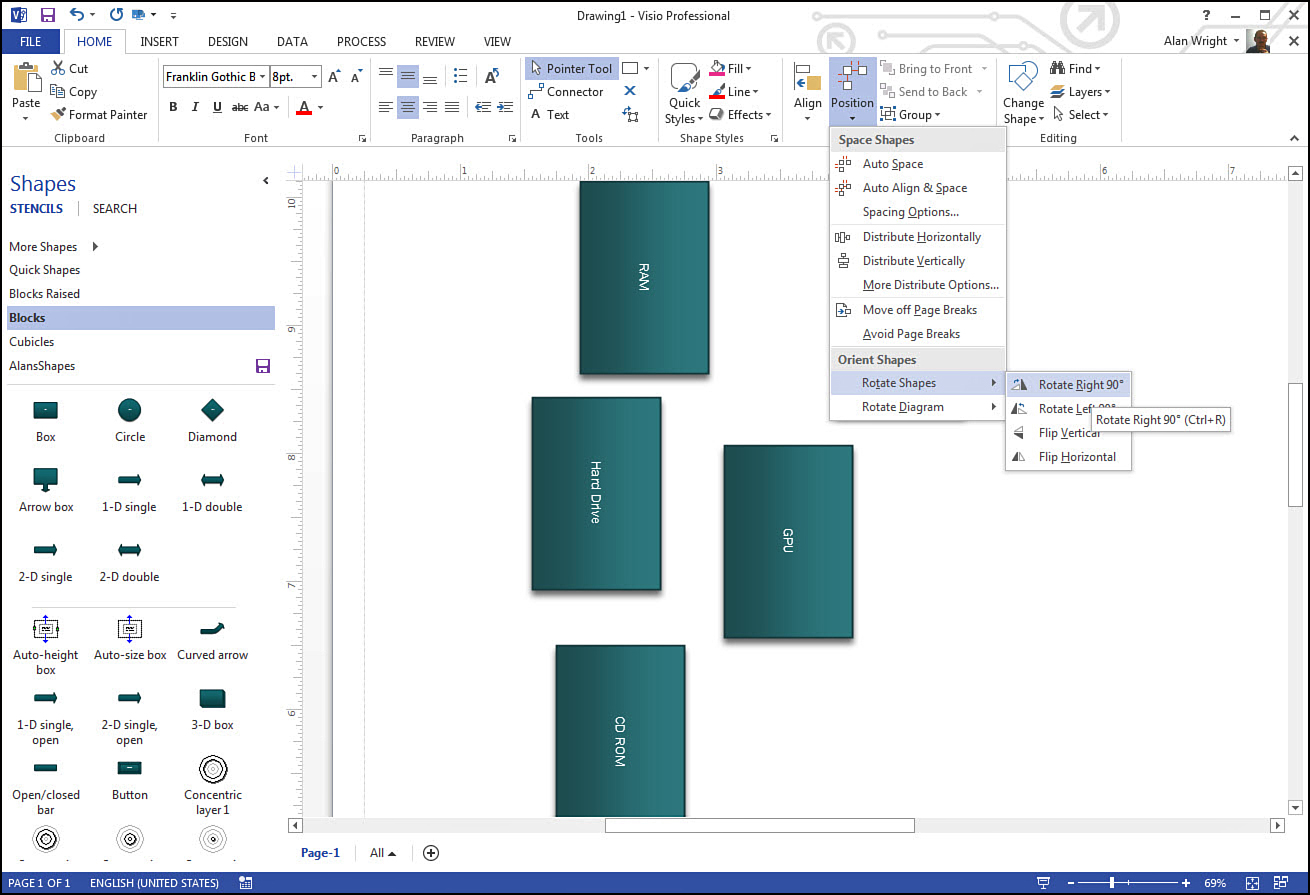
Also under the Position button on the Home tab are several Orient Shapes tools related to rotation. As shown in Figure 6.14, the Rotate Shapes tool allows you to rotate the selected shapes or flip the selected shapes from left to right or top to bottom. (Compare to the orientation shown in Figure 6.7 before rotation.) The results are similar to the basic Rotate tools you use when working with photos.
 Caution
If you use Flip Vertical, the shapes appear upside down, whereas the text maintains the orientation. There may be unintended consequences of flipping a shape with this tool. For example, gradients display upside down compared to unselected shapes.
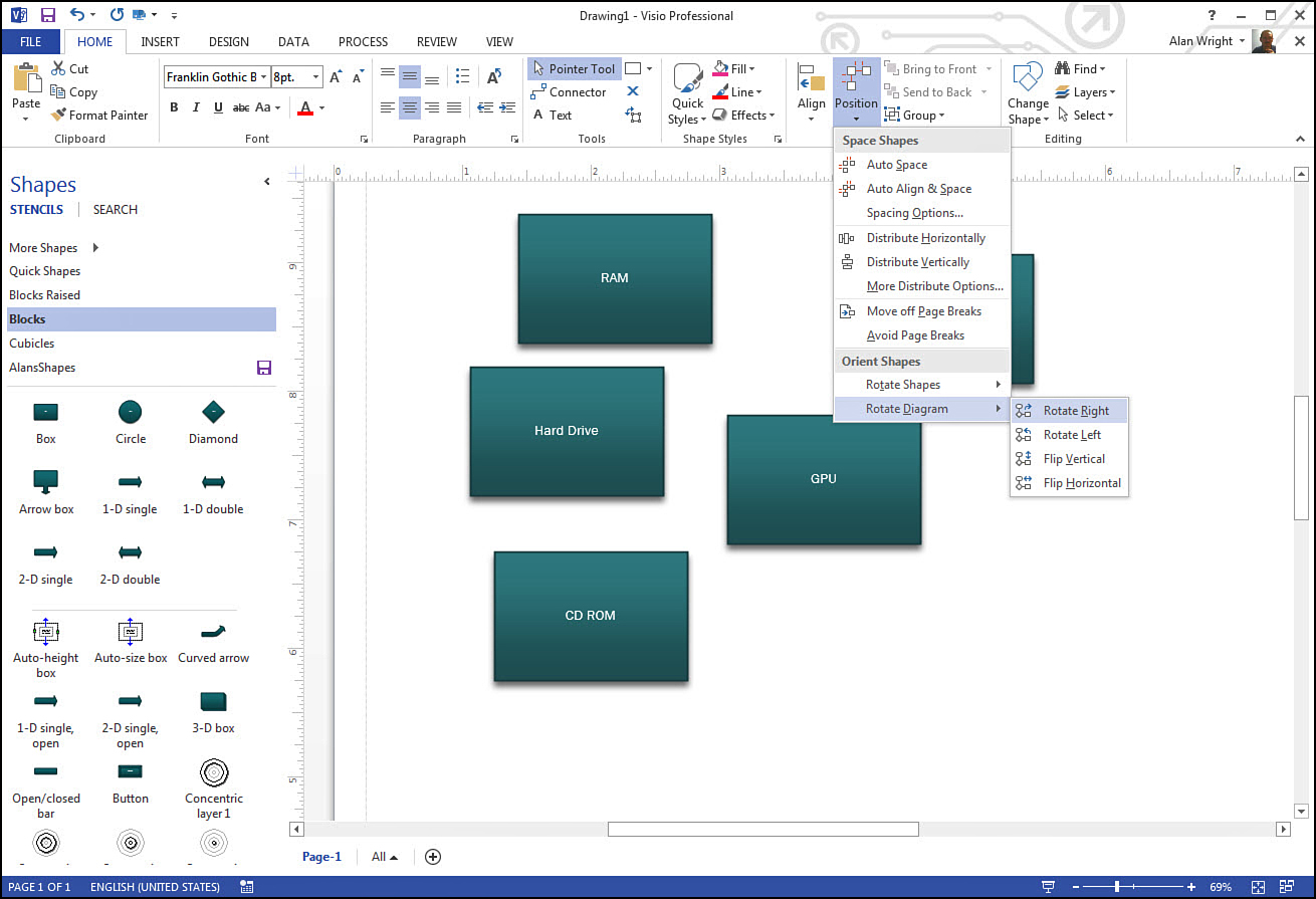
Rotate Diagram tools allow you to rotate the orientation or position of the shapes with one another. Compare Figure 6.15 with 6.14 to see the difference between the shape orientation and rotating the diagram orientation. (Compare to the orientation shown in Figure 6.7 before rotation.)
When using the tools listed under Orient Shapes, you might encounter overlapping shapes. The preview is invaluable in determining whether the tool accomplishes the desired change.
Many of the tools under Align and Position are especially designed to work with connected shapes; therefore, they may have a stronger visual effect when shapes are connected.
Old-School Grid, Ruler, and Guides
Maybe you have worked with graph paper in the past. There was a time when all designers relied on lined graph paper and hand-drawn drafting equipment when doing design work (I still have my T-square!). Visio was designed back when those techniques were still fresh in the minds of users and are included to this day. Although Dynamic Grid allows you to have the benefits of these tools without the need to have visual references on the drawing window, Grid is still a nice option for some situations. (Sorry, Visio licenses do not cover riding a Light Cycle around on a grid, although that would be an awesome selling feature!) The Ruler and Guides tools are generally enabled by default. Nevertheless, you can easily show or hide these visual cues from the View tab by checking their boxes, as shown in Figure 6.16. Enabling the grid in your drawing window does not cause the grid to be printed; that is a separate setting.
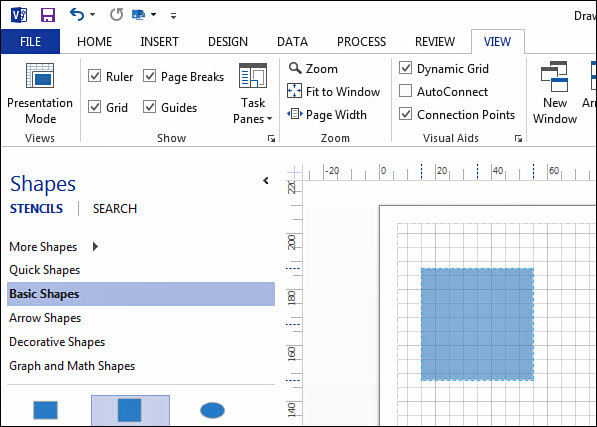
FIGURE 6.16 Visual tools like the Grid can be shown or hidden from the View tab. Guidelines show where the shape is in relation to the ruler.
When zooming in and out of a drawing, the grid adjusts to maintain the same size reference squares. To prevent this and to make other adjustments to the ruler, open the View tab and then open the Ruler and Grid dialog box. This is the small launcher button under Task Panes in the Show section of the View tab. Notice in Figure 6.17 that you can lock in values for the grid size, and even increments used by the ruler.
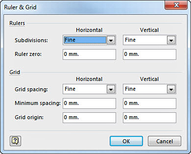
FIGURE 6.17 The Ruler & Grid dialog box allows you to tweak display settings for the grid and ruler.
Under Visual Aids on the View tab, you can launch the Snap & Grid dialog box to enable or disable how shapes react to the grid. The General tab displayed in Figure 6.18 has options for both shapes and connectors. The Advanced tab allows you to adjust the strength of these tools. Be cautious about making drastic changes here because the effects could become quite frustrating later by enabling or over strengthening a setting.
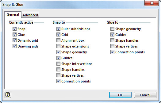
FIGURE 6.18 The Snap & Glue dialog box provides options to enable or disable the Snap to Grid or Ruler subdivisions.
When Overlaps Occur
As much as you may try to avoid overlaps, they can occur as your diagram evolves and becomes more complex or as processes or components are added. In some cases the overlap is intended, but the shape may hide rather than slip behind another shape. There are a few techniques for dealing with this. Although 2D drawing refers to X and Y coordinates, overlapping shapes make this a 3D problem and you now use the Z coordinate or ‘z-order’ as it’s commonly referred to in Visio circles.
Z-Order
Z-order refers to the positioning from front to back. New shapes are placed on top of older shapes by default. In the Home tab look at the Arrange section again. There are two drop-down options you can use to quickly change the z-order of a shape (see Figure 6.19).
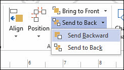
FIGURE 6.19 It is easy to change the z-order of your shapes with the Bring to Front and Send to Back menus.
• Bring to Front puts the selected shape in front of all overlapping objects (use Shift+Ctrl+F).
• Bring Forward puts the selected shape one position forward in a stack of overlapping objects.
• Send Backward moves the selected shape one position down in a stack.
• Send to Back places the selected shape behind all other overlapped objects (use Shift+Ctrl+B).
Using Layout to Organize Shapes
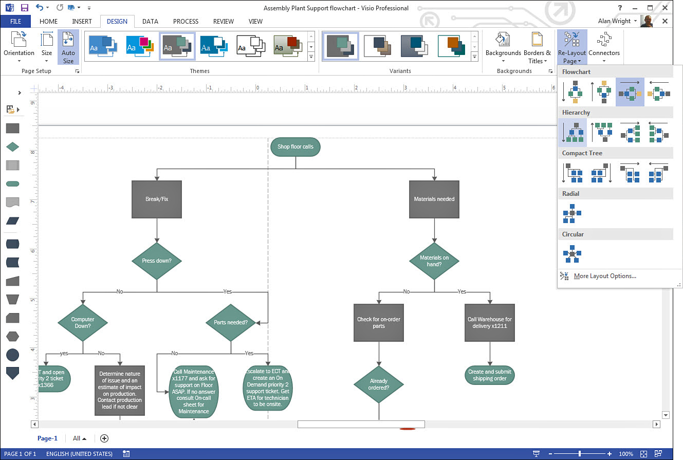
Layout is a very powerful tool in Visio that is used to improve and correct certain types of drawings such as flowcharts. When quickly putting steps or processes together, you may have steps or processes accurately represented, but not efficiently visualized. Back in Chapter 3, “Working with Basic Diagrams,” a flowchart is shown in Figure 3.15. Notice that same flowchart with a hierarchal layout applied in Figure 6.20. When you click the Re-Layout Page drop-down and then choose the best layout, the entire flowchart is redrawn in what may be a more efficient manner.
Tip
Re-Layout Page is especially useful after edits or additions have occurred that impact the appearance of your charts. Rather than trying to manually rearrange the steps or content, see if the Layout tool can fix the chart.
Notice that the button labeled Re-Layout Page from Layout section of the Design tab provides choices for Flowcharts, Hierarchy, Compact Tree, Radial, and Circular charts. More Layout Options opens the Page Setup dialog box; click the Layout and Routing tab where you can further adjust the overall layout of the page.