
Chapter 4. Moving Data
What You’ll Learn in This Chapter
• How to manage the state of resources as they are used by Vulkan
• How to copy data between resources and fill buffers and images with a known value
• How to perform blit operations to stretch and scale image data
Graphics and compute operations are generally data-intensive. Vulkan includes several objects that provide a means to store and manipulate data. It is often necessary to move data into and out of those objects, and several commands are provided to do exactly that: copy data and fill buffer and image objects. Further, at any given time a resource may be in one of any number of states, and many parts of the Vulkan pipeline may need access to them. This chapter covers data movement commands that can be used to copy data and fill memory—the commands needed to manage the state of resources as they are accessed by your applications.
Chapter 3, “Queues and Commands,” showed that commands executed by the device are placed in command buffers and submitted to one of its queues for execution. This is important because it means that commands are not executed as you call them in your application, but as they are encoutered by the device while it makes its way through the command buffers you’ve submitted. The first command you were introduced to, vkCmdCopyBuffer(), copies data between two buffers or between different regions in the same buffer. This is one of may commands that affect buffers, images, and other objects in Vulkan. This chapter covers similar commands for filling, copying, and clearing buffers and images.
Managing Resource State
At any given time in the execution of a program, each resource can be in one of many different states. For example, if the graphics pipeline is drawing to an image or using it as the source of texture data, or if Vulkan is copying data from the host into an image, each of those usage scenarios is different. For some Vulkan implementations, there may be no real difference between some of these states, and for others, accurately knowing the state of a resource at a given point in time can make the difference between your application working or rendering junk.
Because commands in command buffers are responsible for most access to resources, and because command buffers might be built in a different order from the order in which they are submitted for execution, it’s not really practical for Vulkan implementations to attempt to track the state of a resource and make sure it’s in the right one for each usage scenario. In particular, a resource may begin in one state and move to another due to the execution of a command buffer. While drivers could track the state of resources as they are used in a command buffer, tracking state across command buffers would require significant effort1 when the command buffers were submitted for execution. Therefore, this responsibility falls to your application. Resource state is perhaps most important for images because they are complex, structured resources.
1. The validation layers do, in fact, attempt to track this state. While this comes with a substantial performance impact, the layer is capable of catching and reporting many resource-state-related issues.
The state of an image is roughly divided into two essentially orthogonal pieces of state: its layout, which determines how the data is laid out in memory and was discussed briefly earlier in the book, and a record of who last wrote to the image, which affects caching and coherency of data on the device. The initial layout of an image is specified when it is created, and then can be changed throughout the image’s lifetime, either explicitly using barriers or implicitly using renderpass. Barriers also marshal access to resources from different parts of the Vulkan pipeline, and in some cases, transitioning a resource from one layout to another can be accomplished at other midpipeline synchronization work performed by barriers.
The specific use cases for each layout are discussed in some depth later in the book. However, the fundamental act of moving a resource from state to state is known as a barrier, and it is extremely important to get barriers right and to use them effectively in your application.
Pipeline Barriers
A barrier is a synchronization mechanism for memory access mamangement and resource state movement within the stages of the Vulkan pipeline. The primary command for synchronizing access to resources and moving them from state to state is vkCmdPipelineBarrier(), the prototype of which is
void vkCmdPipelineBarrier (
VkCommandBuffer commandBuffer,
VkPipelineStageFlags srcStageMask,
VkPipelineStageFlags dstStageMask,
VkDependencyFlags dependencyFlags,
uint32_t memoryBarrierCount,
const VkMemoryBarrier* pMemoryBarriers,
uint32_t bufferMemoryBarrierCount,
const VkBufferMemoryBarrier* pBufferMemoryBarriers,
uint32_t imageMemoryBarrierCount,
const VkImageMemoryBarrier* pImageMemoryBarriers);
The command buffer that will execute the barrier is passed in commandBuffer. The next two parameters, srcStageMask and dstStageMask, specify which pipeline stages wrote to the resource last and which stages will read from the resource next, respectively. That is, they specify the source and destination for the data flow represented by the barrier. Each is constructed from a number of the members of the VkPipelineStageFlagBits enumeration.
• VK_PIPELINE_STAGE_TOP_OF_PIPE_BIT: The top of pipe is considered to be hit as soon as the device starts processing the command.
• VK_PIPELINE_STAGE_DRAW_INDIRECT_BIT: When the pipeline executes an indirect command, it fetches some of the parameters for the command from memory. This is the stage that fetches those parameters.
• VK_PIPELINE_STAGE_VERTEX_INPUT_BIT: This is the stage where vertex attributes are fetched from their respective buffers. After this, content of vertex buffers can be overwritten, even if the resulting vertex shaders have not yet completed execution.
• VK_PIPELINE_STAGE_VERTEX_SHADER_BIT: This stage is passed when all vertex shader work resulting from a drawing command is completed.
• VK_PIPELINE_STAGE_TESSELLATION_CONTROL_SHADER_BIT: This stage is passed when all tessellation control shader invocations produced as the result of a drawing command have completed execution.
• VK_PIPELINE_STAGE_TESSELLATION_EVALUATION_SHADER_BIT: This stage is passed when all tessellation evaluation shader invocations produced as the result of a drawing command have completed execution.
• VK_PIPELINE_STAGE_GEOMETRY_SHADER_BIT: This stage is passed when all geometry shader invocations produced as the result of a drawing command have completed execution.
• VK_PIPELINE_STAGE_FRAGMENT_SHADER_BIT: This stage is passed when all fragment shader invocations produced as the result of a drawing command have completed execution. Note that there is no way to know that a primitive has been completely rasterized while the resulting fragment shaders have not yet completed. However, rasterization does not access memory, so no information is lost here.
• VK_PIPELINE_STAGE_EARLY_FRAGMENT_TESTS_BIT: All per-fragment tests that might occur before the fragment shader is launched have completed.
• VK_PIPELINE_STAGE_LATE_FRAGMENT_TESTS_BIT: All per-fragment tests that might occur after the fragment shader is executed have completed. Note that outputs to the depth and stencil attachments happen as part of the test, so this stage and the early fragment test stage include the depth and stencil outputs.
• VK_PIPELINE_STAGE_COLOR_ATTACHMENT_OUTPUT_BIT: Fragments produced by the pipeline have been written to the color attachments.
• VK_PIPELINE_STAGE_COMPUTE_SHADER_BIT: Compute shader invocations produced as the result of a dispatch have completed.
• VK_PIPELINE_STAGE_TRANSFER_BIT: Any pending transfers triggered as a result of calls to vkCmdCopyImage() or vkCmdCopyBuffer(), for example, have completed.
• VK_PIPELINE_STAGE_BOTTOM_OF_PIPE_BIT: All operations considered to be part of the graphics pipeline have completed.
• VK_PIPELINE_STAGE_HOST_BIT: This pipeline stage corresponds to access from the host.
• VK_PIPELINE_STAGE_ALL_GRAPHICS_BIT: When used as a destination, this special flag means that any pipeline stage may access memory. As a source, it’s effectively equivalent to VK_PIPELINE_STAGE_BOTTOM_OF_PIPE_BIT.
• VK_PIPELINE_STAGE_ALL_COMMANDS_BIT: This stage is the big hammer. Whenever you just don’t know what’s going on, use this; it will synchronize everything with everything. Just use it wisely.
Because the flags specified in srcStageMask and dstStageMask are used to indicate when things happen, it’s acceptable for Vulkan implementations to move them around or interpret them in various ways. The srcStageMask specifies when the source stage has finished reading or writing a resource. As a result, moving the effective position of that stage later in the pipeline doesn’t change the fact that those accesses have completed; it may mean only that the implementation waits longer than it really needs to for them to complete.
Likewise, the dstStageMask specifies the point at which the pipeline will wait before proceeding. If an implementation moves that wait point earlier, that will still work. The event that it waits on will still have completed when the logically later parts of the pipeline begin execution. That implementation just misses the opportunity to perform work when it was instead waiting.
The dependencyFlags parameter specifies a set of flags that describes how the dependency represented by the barrier affects the resources referenced by the barrier. The only defined flag is VK_DEPENDENCY_BY_REGION_BIT, which indicates that the barrier affects only the region modified by the source stages (if it can be determined), which is consumed by the destination stages.
A single call to vkCmdPipelineBarrier() can be used to trigger many barrier operations. There are three types of barrier operations: global memory barriers, buffer barriers, and image barriers. Global memory barriers affect things such as synchronized access to mapped memory between the host and the device. Buffer and image barriers primarily affect device access to buffer and image resources, respectively.
Global Memory Barriers
The number of global memory barriers to be triggered by vkCmdPipelineBarrier() is specified in memoryBarrierCount. If this is nonzero, then pMemoryBarriers points to an array of memoryBarrierCount VkMemoryBarrier structures, each defining a single memory barrier. The definition of VkMemoryBarrier is
typedef struct VkMemoryBarrier {
VkStructureType sType;
const void* pNext;
VkAccessFlags srcAccessMask;
VkAccessFlags dstAccessMask;
} VkMemoryBarrier;
The sType field of VkMemoryBarrier should be set to VK_STRUCTURE_TYPE_MEMORY_BARRIER, and pNext should be set to nullptr. The only other fields in the structure are the source and destination access masks specified in srcAccessMask and dstAccessMask, respectively. The access masks are bitfields containing members of the VkAccessFlagBits. The source access mask specifies how the memory was last written, and the destination access mask specifies how the memory will next be read. The available access flags are
• VK_ACCESS_INDIRECT_COMMAND_READ_BIT: The memory referenced will be the source of commands in an indirect drawing or dispatch command such as vkCmdDrawIndirect() or vkCmdDispatchIndirect().
• VK_ACCESS_INDEX_READ_BIT: The memory referenced will be the source of index data in an indexed drawing command such as vkCmdDrawIndexed() or vkCmdDrawIndexedIndirect().
• VK_ACCESS_VERTEX_ATTRIBUTE_READ_BIT: The memory referenced will be the source of vertex data fetched by Vulkan’s fixed-function vertex assembly stage.
• VK_ACCESS_UNIFORM_READ_BIT: The memory referenced is the source of data for a uniform block accessed by a shader.
• VK_ACCESS_INPUT_ATTACHMENT_READ_BIT: The memory referenced is used to back an image used as an input attachment.
• VK_ACCESS_SHADER_READ_BIT: The memory referenced is used to back an image object that is read from using image loads or texture reads in a shader.
• VK_ACCESS_SHADER_WRITE_BIT: The memory referenced is used to back an image object that is written to using image stores in a shader.
• VK_ACCESS_COLOR_ATTACHMENT_READ_BIT: The memory referenced is used to back an image used as a color attachment where reads are performed, perhaps because blending is enabled. Note that this is not the same as an input attachment, where data is read explicitly by the fragment shader.
• VK_ACCESS_COLOR_ATTACHMENT_WRITE_BIT: The memory referenced is used to back an image used as a color attachment that will be written to.
• VK_ACCESS_DEPTH_STENCIL_ATTACHMENT_READ_BIT: The memory referenced is used to back an image used as a depth or stencil attachment that will be read from because the relevant test is enabled.
• VK_ACCESS_DEPTH_STENCIL_ATTACHMENT_WRITE_BIT: The memory referenced is used to back an image used as a depth or stencil attachment that will be written to because the relevant write mask is enabled.
• VK_ACCESS_TRANSFER_READ_BIT: The memory referenced is used as the source of data in a transfer operation such as vkCmdCopyImage(), vkCmdCopyBuffer(), or vkCmdCopyBufferToImage().
• VK_ACCESS_TRANSFER_WRITE_BIT: The memory referenced is used as the destination of a transfer operation.
• VK_ACCESS_HOST_READ_BIT: The memory referenced is mapped and will be read from by the host.
• VK_ACCESS_HOST_WRITE_BIT: The memory referenced is mapped and will be written to by the host.
• VK_ACCESS_MEMORY_READ_BIT: All other memory reads not explicitly covered by the preceding cases should specify this bit.
• VK_ACCESS_MEMORY_WRITE_BIT: All other memory writes not explicitly covered by the preceding cases should specify this bit.
Memory barriers provide two important pieces of functionality. First, they help avoid hazards, and second, they help ensure data consistency.
A hazard occurs when read and write operations are reordered relative to the order in which the programmer expects them to execute. They can be very hard to diagnose because they are often platform- or timing-dependent. There are three types of hazards:
• A read-after-write, or RaW, hazard occurs when the programmer expects to read from a piece of memory that has recently been written to and that those reads will see the results of the writes. If the read is rescheduled and ends up executing before the write is complete, the read will see old data.
• A write-after-read, or WaR, hazard occurs when a programmer expects to overwrite a piece of memory that had previously been read by another part of the program. If the write operation ends up being scheduled before the read operation, then the read operation will see the new data, not the older data it was expecting.
• A write-after-write, or WaW, hazard occurs when a programmer expects to overwrite the same location in memory multiple times and that only the results of the last write will be visible to subsequent readers. If the writes are rescheduled with respect to one another, then only the result of the write that happened to execute last will be visible to readers.
There is no such thing as a read-after-read hazard because no data is modified.
In the memory barrier, the source isn’t necessarily a producer of data but the first operation that is protected by that barrier. For avoiding RaW hazards, the source is actually a read operation.
For example, to ensure that all texture fetches are complete before overwriting an image with a copy operation, we need to specify VK_ACCESS_SHADER_READ_BIT in the srcAccessMask field and VK_ACCESS_TRANSFER_WRITE_BIT in the dstAccessMask field. This tells Vulkan that the first stage is reading from an image in a shader and that the second stage may overwrite that image, so we should not reorder the copy into the image before any shaders that may have read from it.
Note that there is some overlap between the bits in VkAccessFlagBits and those in VkPipelineStageFlagBits. The VkAccessFlagBits flags specify what operation is being performed, and the VkPipelineStageFlagBits describe where in the pipeline the action is performed.
The second piece of functionality provided by the memory barrier is to ensure consistency of the views of data from different parts of the pipeline. For example, if an application contains a shader that writes to a buffer from a shader and then needs to read that data back from the buffer by mapping the underlying memory object, it should specify VK_ACCESS_SHADER_WRITE_BIT in srcAccessMask and VK_ACCESS_HOST_READ_BIT in dstAccessMask. If there are caches in the device that may buffer writes performed by shaders, those caches may need to be flushed in order for the host to see the results of the write operations.
Buffer Memory Barriers
Buffer memory barriers provide finer-grained control of the memory used to back buffer objects. The number of buffer memory barriers executed by a call to vkCmdPipelineBarrier() is specified in the bufferMemoryBarrierCount parameter, and the pBufferMemoryBarriers field is a pointer to an array of this many VkBufferMemoryBarrier structures, each defining a buffer memory barrier. The definition of VkBufferMemoryBarrier is
typedef struct VkBufferMemoryBarrier {
VkStructureType sType;
const void* pNext;
VkAccessFlags srcAccessMask;
VkAccessFlags dstAccessMask;
uint32_t srcQueueFamilyIndex;
uint32_t dstQueueFamilyIndex;
VkBuffer buffer;
VkDeviceSize offset;
VkDeviceSize size;
} VkBufferMemoryBarrier;
The sType field of each VkBufferMemoryBarrier structure should be set to VK_STRUCTURE_TYPE_BUFFER_MEMORY_BARRIER, and pNext should be set to nullptr. The srcAccessMask and dstAccessMask fields have the same meanings as they do in the VkMemoryBarrier structure. Obviously, some of the flags that refer specifically to images, such as color or depth attachments, have little meaning when dealing with buffer memory.
When ownership of the buffer is being transferred from one queue to another and those queues are in different families, the family indices of the source and destination queues must be supplied in srcQueueFamilyIndex and dstQueueFamilyIndex, respectively. If there is no transfer of ownership, then srcQueueFamilyIndex and dstQueueFamilyIndex can both be set to VK_QUEUE_FAMILY_IGNORED. In this case, the sole ownership is assumed to be the queue family for which the command buffer is being built.
The buffer the access to which is being controlled by the barrier is specified in buffer. To synchronize access to a range of a buffer, use the offset and size fields of the structure to specify that range, in bytes. To control access to the whole buffer, simply set offset to zero and size to VK_WHOLE_SIZE.
If the buffer will be accessed by work executing on more than one queue, and those queues are of different families, additional action must be taken by your application. Because a single device exposing multiple queue families may actually be made up of multiple physical components, and because those components may have their own caches, scheduling architecture, memory controllers, and so on, Vulkan needs to know when a resource is moved from queue to queue. If this is the case, specify the queue family index of the source queue in srcQueueFamilyIndex and the family of the destination queue in dstQueueFamilyIndex.
Similarly to image memory barriers, if the resource is not being transferred between queues belonging to different families, srcQueueFamilyIndex and dstQueueFamilyIndex should be set to VK_QUEUE_FAMILY_IGNORED.
Image Memory Barriers
Just as with buffers, special attention should be paid to images, and image memory barriers are used to control access to images. The number of image memory barriers to be performed by the call to vkCmdPipelineBarrier() is specified in the imageMemoryBarrierCount parameter, and pImageMemoryBarriers is a pointer to an array of this many VkImageMemoryBarrier structures, each describing a single barrier. The definition of VkImageMemoryBarrier is
typedef struct VkImageMemoryBarrier {
VkStructureType sType;
const void* pNext;
VkAccessFlags srcAccessMask;
VkAccessFlags dstAccessMask;
VkImageLayout oldLayout;
VkImageLayout newLayout;
uint32_t srcQueueFamilyIndex;
uint32_t dstQueueFamilyIndex;
VkImage image;
VkImageSubresourceRange subresourceRange;
} VkImageMemoryBarrier;
The sType field of each VkImageMemoryBarrier structure should be set to VK_STRUCTURE_TYPE_IMAGE_MEMORY_BARRIER, and pNext should be set to nullptr. Just as with the other memory barriers, the srcAccessMask and dstAccessMask fields specify the source and destination access type. Again, only some of the access types will apply to images. Also, when you are controlling access across queues, the srcQueueFamilyIndex and dstQueueFamilyIndex fields should be set to the family indices of the queues where the source and destination work will take place.
The oldLayout and newLayout fields specify the layouts to be used for the image before and after the barrier. These are the same fields that can be used when creating the image. The image that the barrier is to affect is specified in image, and the parts of the image to be affected by the barrier are specified in subresourceRange, which is an instance of the VkImageSubresourceRange structure, the definition of which is
typedef struct VkImageSubresourceRange {
VkImageAspectFlags aspectMask;
uint32_t baseMipLevel;
uint32_t levelCount;
uint32_t baseArrayLayer;
uint32_t layerCount;
} VkImageSubresourceRange;
The image aspect is the part of the image that is to be included in the barrier. Most image formats and types have only a single aspect. A common exception is a depth-stencil image, which may have a separate aspect for each of the depth and stencil components of the image. It is possible, using the aspect flags, to discard stencil data while keeping depth data for later sampling, for example.
For images with mipmaps, a subset of the mipmaps can be included in the barrier by specifying the lowest-numbered (highest-resolution) mipmap level in the baseMipLevel field and the number of levels in the levelCount field. If the image doesn’t have a full mipmap chain, baseMipLevel should be set to 0, and levelCount should be set to 1.
Likewise, for array images, a subset of the image layers can be included in the barrier by setting baseArrayLayer to the index of the first layer and layerCount to the number of layers to include. Again, even if the image is not an array image, you should set baseArrayLayer to 0 and layerCount to 1. In short, treat all images as though they have mipmaps (even if it’s only one level) and all images as though they are arrays (even if they have only one layer).
Listing 4.1 shows an example of how to perform an image memory barrier.
Listing 4.1: Image Memory Barrier
const VkImageMemoryBarrier imageMemoryBarriers =
{
VK_STRUCTURE_TYPE_IMAGE_MEMORY_BARRIER, // sType
nullptr, // pNext
VK_ACCESS_COLOR_ATTACHMENT_WRITE_BIT, // srcAccessMask
VK_ACCESS_SHADER_READ_BIT, // dstAccessMask
VK_IMAGE_LAYOUT_COLOR_ATTACHMENT_OPTIMAL, // oldLayout
VK_IMAGE_LAYOUT_SHADER_READ_ONLY_OPTIMAL, // newLayout
VK_QUEUE_FAMILY_IGNORED, // srcQueueFamilyIndex
VK_QUEUE_FAMILY_IGNORED, // dstQueueFamilyIndex
image, // image
{ // subresourceRange
VK_IMAGE_ASPECT_COLOR_BIT, // aspectMask
0, // baseMipLevel
VK_REMAINING_MIP_LEVELS, // levelCount
0, // baseArrayLayer
VK_REMAINING_ARRAY_LAYERS // layerCount
}
};
vkCmdPipelineBarrier(m_currentCommandBuffer,
VK_PIPELINE_STAGE_COLOR_ATTACHMENT_OUTPUT_BIT,
VK_PIPELINE_STAGE_FRAGMENT_SHADER_BIT,
0,
0, nullptr,
0, nullptr,
1, &imageMemoryBarrier);
The image memory barrier shown in Listing 4.1 takes an image that was previously in the VK_IMAGE_LAYOUT_COLOR_ATTACHMENT_OPTIMAL layout and moves it to the VK_IMAGE_LAYOUT_SHADER_READ_ONLY_OPTIMAL layout. The source of data is the color output from the pipeline, as specified by VK_ACCESS_COLOR_ATTACHMENT_WRITE_BIT, and the destination of the data is sampling by a shader, as specified by VK_ACCESS_SHADER_READ_BIT.
There is no transfer of ownership across queues, so both srcQueueFamilyIndex and dstQueueFamilyIndex are set to VK_QUEUE_FAMILY_IGNORED. Also, we’re performing the barrier across all mipmap levels and array layers in the image, so the levelCount and layerCount members of the subresourceRange structure are set to VK_REMAINING_MIP_LEVELS and VK_REMAINING_ARRAY_LAYERS, respectively.
This barrier takes an image that previously was written to as a color attachment by a graphics pipeline and moves it into a state in which it can be read from by a shader.
Clearing and Filling Buffers
You were introduced to buffer objects in Chapter 2, “Memory and Resources.” A buffer is a linear region of data backed by memory. In order for a buffer to be useful, you need to be able to fill it with data. In some cases, simply clearing the whole buffer to a known value is all you need to do. This allows you to, for example, initialize a buffer that you will eventually write into using a shader or some other operation.
To fill a buffer with a fixed value, call vkCmdFillBuffer(), the prototype of which is
void vkCmdFillBuffer (
VkCommandBuffer commandBuffer,
VkBuffer dstBuffer,
VkDeviceSize dstOffset,
VkDeviceSize size,
uint32_t data);
The command buffer into which to place the command is specified in commandBuffer. The buffer that will be filled with data is specified in dstBuffer. To fill a section of the buffer with data, specify the starting offset of the fill operation, in bytes, in dstOffset and the size of the region, again in bytes, in size. Both dstOffset and size must be multiples of 4. To fill from dstOffset to the end of the buffer, pass the special value, VK_WHOLE_SIZE, in the size parameter. It follows that to fill an entire buffer, simply set dstOffset to 0 and size to VK_WHOLE_SIZE.
The value that you want to fill the buffer with is passed in data. This is a uint32_t variable that is simply replicated for the region of the fill operation. It is as though the buffer is interpreted as an array of uint32_t, and each element from dstOffset to the end of the region is filled with this value. To clear a buffer with a floating-point value, you can reinterpret the floating-point value as a uint32_t value and pass that to vkCmdFillBuffer(). Listing 4.2 demonstrates this.
Listing 4.2: Filling a Buffer with Floating-Point Data
void FillBufferWithFloats(VkCommandBuffercmdBuffer,
VkBuffer dstBuffer,
VkDeviceSize offset,
VkDeviceSize length,
const float value)
{
vkCmdFillBuffer(cmdBuffer,
dstBuffer,
0,
1024,
*(const uint32_t*)&value);
}
Sometimes, filling a buffer with a fixed value is not enough, and there is a need to place data more explicitly in a buffer object. When a large amount of data is needed to be transfered into or between buffers, either mapping the buffer and writing to it with the host or copying data from another (possibly mapped) buffer with vkCmdCopyBuffer() is most appropriate. However, for small updates, such as updating the values of a vector or small data structures, vkCmdUpdateBuffer() can be used to place data directly into a buffer object.
The prototype for vkCmdUpdateBuffer() is
void vkCmdUpdateBuffer (
VkCommandBuffer commandBuffer,
VkBuffer dstBuffer,
VkDeviceSize dstOffset,
VkDeviceSize dataSize,
const uint32_t* pData);
vkCmdUpdateBuffer() copies data directly from host memory into a buffer object. The data is consumed from host memory as soon as vkCmdUpdateBuffer() is called, and as such, it’s fine to free the host memory data structure or overwrite its content once vkCmdUpdateBuffer() returns. Be aware, though, that the data is not written into the buffer until vkCmdUpdateBuffer() is executed by the device after the command buffer has been submitted. For this reason, Vulkan must make a copy of the data you’ve supplied and hold it either in some auxiliary data structure associated with the command buffer or directly inside the command buffer itself.
Again, the command buffer that will contain the command is passed in commandBuffer, and the destination buffer object is passed in dstBuffer. The offset at which the data is to be placed is passed in dstOffset, and the size of the data to place into the buffer is passed in dataSize. Both dstOffset and dataSize are in units of bytes, but as with vkCmdFillBuffer(), both must be a multiple of 4. The special value VK_WHOLE_SIZE is not accepted for the size parameter to vkCmdUpdateBuffer() because it is also used as the size of the host memory region that is the source of the data. The maximum size of data that can be placed in a buffer with vkCmdUpdateBuffer() is 65,536 bytes.
pData points to the host memory containing the data that will eventually be placed into the buffer object. Although the type of the variable expected here is a pointer to uint32_t, any data can be in the buffer. Simply typecast a pointer to any memory region readable by the host to const uint32_t*, and pass it to pData. Ensure that the data region is at least size bytes long. For example, it’s reasonable to construct a C++ data structure matching the layout of a uniform or shader storage block and simply copy its entire content into a buffer that will be used appropriately in a shader.
Again, be cautious when using vkCmdFillBuffer(). It is intended for short, immediate updates to buffers. For example, writing a single value into a uniform buffer is probably much more efficiently achieved with vkCmdFillBuffer() than it is with a buffer mapping and a call to vkCmdCopyBuffer().
Clearing and Filling Images
Just as with buffers, it it possible to copy data directly between images and to fill images with fixed values. Images are larger, more complex, opaque data structures, so the raw offsets and data are not generally visible to an application.2
2. Of course, it’s possible to map the memory that is used for backing an image. In particular, when linear tiling is used for an image, this is standard practice. However, in general, this is not recommended.
To clear an image to a fixed value, call vkCmdClearColorImage(), the prototype of which is
void vkCmdClearColorImage (
VkCommandBuffer commandBuffer,
VkImage image,
VkImageLayout imageLayout,
const VkClearColorValue* pColor,
uint32_t rangeCount,
const VkImageSubresourceRange* pRanges);
The command buffer that will contain the clear command is passed in commandBuffer. The image that is to be cleared is passed in image, and the layout that the image is expected to be in when the clear command is executed is passed in imageLayout.
The accepted layouts for imageLayout are VK_IMAGE_LAYOUT_GENERAL and VK_IMAGE_LAYOUT_TRANSFER_DST_OPTIMAL. To clear images that are in different layouts, it is necessary to move them to one of these two layouts using a pipeline barrier before executing the clear command.
The values to clear the image to are specified in an instance of the VkClearColorValue union, the definition of which is
typedef union VkClearColorValue {
float float32[4];
int32_t int32[4];
uint32_t uint32[4];
} VkClearColorValue;
The VkClearColorValue is simply a union of three arrays of four values each. One is for floating-point data, one is for signed integer data, and one is for unsigned integer data. Vulkan will read the appropriate member for the format of the image being cleared. Your application can write into the member that matches the source of data. No data conversion is performed by vkCmdClearColorImage(); it is up to your application to fill the VkClearColorValue union correctly.
Any number of regions of the destination image can be cleared with a single call to vkCmdClearColorImage(), although each will be cleared with the same values. If you need to clear multiple regions of the same image with different colors, you will need to call vkCmdClearColorImage() multiple times. However, you want to clear all regions with the same color, specify the number of regions in rangeCount, and pass a pointer to an array of rangeCount VkImageSubresourceRange structures in pRanges. The definition of VkImageSubresourceRange is
typedef struct VkImageSubresourceRange {
VkImageAspectFlags aspectMask;
uint32_t baseMipLevel;
uint32_t levelCount;
uint32_t baseArrayLayer;
uint32_t layerCount;
} VkImageSubresourceRange;
This structure was first introduced in Chapter 2, “Memory and Resources,” when we discussed creation of image view. Here, it is used to define the regions of the image that you want to clear. Because we are clearing a color image, the aspectMask must be set to VK_IMAGE_ASPECT_COLOR_BIT. The baseMipLevel and levelCount fields are used to specify the starting mipmap level and number of levels to clear, respectively, and if the image is an array image, the baseArrayLayer and layerCount fields are used to specify the starting layer and number of layers to clear. If the image is not an array image, these fields should be set to 0 and 1, respectively.
Clearing a depth-stencil image is similar to clearing a color image, except that a special VkClearDepthStencilValue structure is used to specify the clear values. The prototype of vkCmdClearDepthStencilImage() is similar to that of vkCmdClearColorImage() and is
void vkCmdClearDepthStencilImage (
VkCommandBuffer commandBuffer,
VkImage image,
VkImageLayout imageLayout,
const VkClearDepthStencilValue* pDepthStencil,
uint32_t rangeCount,
const VkImageSubresourceRange * pRanges);
Again, the command buffer that will perform the clear operation is specified in commandBuffer, the image to clear is specified in image, and the layout that the image is expected to be in at the time of the clear operation is specified in imageLayout. As with vkCmdClearColorImage(), imageLayout should be either VK_IMAGE_LAYOUT_GENERAL or VK_IMAGE_LAYOUT_TRANSFER_DST_OPTIMAL. No other layouts are valid for a clear operation.
The values to which to clear the depth-stencil image are passed through an instance of the VkClearDepthStencilValue structure, which contains both the depth and stencil clear values. Its definition is
typedef struct VkClearDepthStencilValue {
float depth;
uint32_t stencil;
} VkClearDepthStencilValue;
As with vkCmdClearColorImage(), a number of ranges of the image can be cleared in a single call to vkCmdClearDepthStencilImage(). The number of ranges to clear is specified in rangeCount, and the pRanges parameter should point to an array of rangeCount VkImageSubresourceRange structures defining the ranges to be cleared.
Because depth-stencil images may contain both a depth and a stencil aspect, the aspectMask field of each member of pRanges can contain VK_IMAGE_ASPECT_DEPTH_BIT, VK_IMAGE_ASPECT_STENCIL_BIT, or both. If aspectMask contains VK_IMAGE_ASPECT_DEPTH_BIT, then the value stored in the depth field of the VkClearDepthStencilValue structure is used to clear the depth aspect of the specified range. Likewise, if aspectMask contains VK_IMAGE_ASPECT_STENCIL_BIT, then the stencil aspect of the specified range will be cleared using the stencil member of the VkClearDepthStencilValue structure.
Note that it’s generally much more efficient to specify a single region with both VK_IMAGE_ASPECT_DEPTH_BIT and VK_IMAGE_ASPECT_STENCIL_BIT set than it is to specify two regions each with only one bit set.
Copying Image Data
In the previous section, we discussed clearing images to a fixed value passed through a simple structure. In many cases, though, you need to upload texture data into images or copy image data between images. Vulkan supports copying image data from a buffer to an image, between images, and from an image to a buffer.
To copy data from a buffer to one or more regions of an image, call vkCmdCopyBufferToImage(), the prototype of which is
void vkCmdCopyBufferToImage (
VkCommandBuffer commandBuffer,
VkBuffer srcBuffer,
VkImage dstImage,
VkImageLayout dstImageLayout,
uint32_t regionCount,
const VkBufferImageCopy* pRegions);
The command buffer that will execute the command is specified in commandBuffer, the source buffer object is specified in srcBuffer, and the image into which the data will be copied is specified in dstImage. As with the destination image in clears, the layout of the destination image for copies is expected to be either VK_IMAGE_LAYOUT_GENERAL or VK_IMAGE_LAYOUT_TRANSFER_DST_OPTIMAL and is specified in the dstImageLayout parameter.
The number of regions to update is given in regionCount, and pRegions is a pointer to an array of regionCount VkBufferImageCopy structures, each definining an area of the image to copy data into. The definition of VkBufferImageCopy is
typedef struct VkBufferImageCopy {
VkDeviceSize bufferOffset;
uint32_t bufferRowLength;
uint32_t bufferImageHeight;
VkImageSubresourceLayers imageSubresource;
VkOffset3D imageOffset;
VkExtent3D imageExtent;
} VkBufferImageCopy;
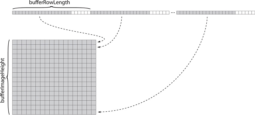
The bufferOffset field contains the offset of the data in the buffer, in bytes. The data in the buffer is laid out left to right, top to bottom, as shown in Figure 4.1. The bufferRowLength field specifies the number of texels in the source image, and bufferImageHeight specifies the number of rows of data in the image. If bufferRowLength is zero, the image is assumed to be tightly packed in the buffer and therefore equal to imageExtent.width. Likewise, if bufferImageHeight is zero, then the number of rows in the source image is assumed to be equal to the height of the image extent, which is in imageExtent.height.
The subresource into which to copy the image data is specified in an instance of the VkImageSubresourceLayers structure, the definition of which is
typedef struct VkImageSubresourceLayers {
VkImageAspectFlags aspectMask;
uint32_t mipLevel;
uint32_t baseArrayLayer;
uint32_t layerCount;
} VkImageSubresourceLayers;
The aspectMask field of VkImageSubresourceLayers contains the aspect or aspects that are the destination of the image copy. Usually, this will be a single bit from the VkImageAspectFlagBits enumeration. If the target image is a color image, then this should simply be set to VK_IMAGE_ASPECT_COLOR_BIT. If the image is a depth-only image, it should be VK_IMAGE_ASPECT_DEPTH_BIT, and if the image is a stencil-only image, it should be VK_IMAGE_ASPECT_STENCIL_BIT. If the image is a combined depth-stencil image, then you can copy data into both the depth and stencil aspects simultaneously by specifying both VK_IMAGE_ASPECT_DEPTH_BIT and VK_IMAGE_ASPECT_STENCIL_BIT.
The target mipmap level is specified in mipLevel. You can copy data into only a single mipmap level with each element in the pRegions array, although you can of course specify multiple elements, each targeting a different level.
If the target image is an array image, then you can specify the starting layer and number of layers for the image copy in baseArrayLayer and layerCount, respectively. If the image is not an array image, then these fields should be set to 0 and 1.
Each region can target either an entire mipmap level or a smaller window within each mipmap level. The offset of the window is specified in imageOffset, and the size of the window is specified in imageExtent. To overwrite an entire mipmap level, set imageOffset.x and imageOffset.y to 0, and set imageExtent.width and imageExtent.height to the size of the mipmap level. It is up to you to calculate this. Vulkan will not do it for you.
It’s also possible to perform the copy in the opposite direction—to copy data from an image into a buffer. To do this, call vkCmdCopyImageToBuffer(), the prototype of which is
void vkCmdCopyImageToBuffer (
VkCommandBuffer commandBuffer,
VkImage srcImage,
VkImageLayout srcImageLayout,
VkBuffer dstBuffer,
uint32_t regionCount,
const VkBufferImageCopy* pRegions);
The command buffer to execute the copy is specified in commandBufer, the source image in srcImage, and the destination buffer in dstBuffer. As with the other copy commands, the srcImageLayout parameter specifies the layout that the source image is expected to be in. Because the image is now the source of data, the layout should either be VK_IMAGE_LAYOUT_GENERAL or VK_IMAGE_LAYOUT_TRANSFER_SRC_OPTIMAL.
Again, a number of regions can be copied in a single call to vkCmdCopyImageToBuffer(), each represented by an instance of the VkBufferImageCopy structure. The number of regions to copy is specified in regionCount, and the pRegions parameter contains a pointer to an array of regionCount VkBufferImageCopy structures defining each of these regions. This is the same structure accepted by vkCmdCopyBufferToImage(). However, in this use case, bufferOffset, bufferRowLength, and bufferImageHeight contain parameters for the destination of the copy, and imageSubresource, imageOffset, and imageExtent contain parameters for the source of the copy.
Finally, it’s also possible to copy data between two images. To do this, use the vkCmdCopyImage() command, the prototype of which is
void vkCmdCopyImage (
VkCommandBuffer commandBuffer,
VkImage srcImage,
VkImageLayout srcImageLayout,
VkImage dstImage,
VkImageLayout dstImageLayout,
uint32_t regionCount,
const VkImageCopy* pRegions);
The command buffer that will execute the command is passed in commandBuffer, the image containing the source data is passed in srcImage, and the image that is the destination for the copy is passed in dstImage. Again, the layout for both images must be passed to the copy command. srcImageLayout is the expected layout of the source image at the time of the copy and should be either VK_IMAGE_LAYOUT_GENERAL or VK_IMAGE_LAYOUT_TRANSFER_SRC_OPTIMAL (as this is the source of a transfer operation). Similarly, dstImageLayout is the expected layout of the destination image and should be either VK_IMAGE_LAYOUT_GENERAL or VK_IMAGE_LAYOUT_TRANSFER_DST_OPTIMAL.
As with the buffer-to-image and image-to-buffer copy commands, vkCmdCopyImage() can copy several regions at a time. The number of regions to copy is specified in regionCount, and each is represented by an instance of the VkImageCopy structure contained in an array, the address of which is passed in pRegions. The definition of VkImageCopy is
typedef struct VkImageCopy {
VkImageSubresourceLayers srcSubresource;
VkOffset3D srcOffset;
VkImageSubresourceLayers dstSubresource;
VkOffset3D dstOffset;
VkExtent3D extent;
} VkImageCopy;
Each instance of VkImageCopy contains the subresource information and offsets for the source and destination windows. vkCmdCopyImage() cannot resize image data, so the extent of the source and destination regions is the same and is contained in the extent field.
srcSubresource contains the subresource definition for the source data and has the same meaning as the imageSubresource field in the VkBufferImageCopy structure passed to vkCmdCopyImageToBuffer(). Likewise, the dstSubresource field contains the subresource definition for the destination region and has the same meaning as the imageSubresource field in the VkBufferImageCopy structure passed to vkCmdCopyBufferToImage().
The srcOffset and dstOffset fields contain the coordinates of the source and destination windows, respectively.
Copying Compressed Image Data
As discussed in Chapter 2, “Memory and Resources,” Vulkan supports a number of compressed image formats. All compression formats currently defined are block-based formats with fixed block sizes. For many of these formats, the block size is 4 × 4 texels. For the ASTC formats, the block size varies by image.
When copying data between buffers and images, only an integral number of blocks may be copied. Therefore, the width and height of each image region, in texels, must be integer multiples of the block size used by the image. Further, the origins of copy regions must also be integer multiples of the block size.
It is also possible to copy data between two compressed images or between a compressed and an uncompressed image using vkCmdCopyImage(). When you do so, the source and destination image formats must have the same compressed block size. That is, if the size of the compressed block is 64 bits, for example, then both the source and destination formats must be compressed images with 64-bit block sizes, or the uncompressed image format must be a 64-bit per-texel format.
When copying from an uncompressed image to a compressed one, each source texel is treated as a single raw value containing the same number of bits as a block in the compressed image. This value is written directly into the compressed image as though it were the compressed data. The texel values are not compressed by Vulkan. This allows you to create compressed image data in your application or shaders and then copy it into compressed images for later processing. Vulkan does not compress raw image data for you. Further, for uncompressed to compressed copies, the extent field of the VkImageCopy structure is in units of texels in the source image but must conform to the block size requirements of the destination image.
When copying from a compressed format to an uncompressed format, the opposite is true. Vulkan does not decompress the image data. Rather, it pulls raw 64-bit or 128-bit compressed block values from the source image and deposits them in the destination image. In this case, the destination image should have the same number of bits per texel as bits per block in the source image. For a compressed to uncompressed copy, the extent field of the VkImageCopy structure is measured in units of texels in the destination image but must conform to the requiremnts imposed by the block size in the source image.
Copying between two block compressed image formats is allowed, so long as both formats have an equal number of bits per block. However, the value of this is debatable, as image data compressed in one format generally does not decode meaningfully when interpreted as another format. Regardless of its worth, when performing this operation, the regions to be copied are still measured in texels, but all offsets and extents must be integer multiples of the common block size.
The only exception to the rule that image copies into, out of, and between compressed images are aligned to multiples of the block size occurs when the source or destination image is not an integer multiple of the block size wide or high, and the region to be copied extends to the edge of the image.
Stretching Images
Of all the image-related commands covered so far, none supports format conversion or resizing of the copied area. To do this, you need to use the vkCmdBlitImage() command, which can take images of different formats and stretch or shrink the region to be copied as it is written into the target image. The term blit is short for block image transfer and refers to the operation of not only copying image data, but potentially also processing it along the way.
The prototype of vkCmdBlitImage() is
void vkCmdBlitImage (
VkCommandBuffer commandBuffer,
VkImage srcImage,
VkImageLayout srcImageLayout,
VkImage dstImage,
VkImageLayout dstImageLayout,
uint32_t regionCount,
const VkImageBlit* pRegions,
VkFilter filter);
The command buffer that will execute the command is passed in commandBuffer. The source and destination images are passed in srcImage and dstImage, respectively. Again, as with vkCmdCopyImage(), the expected layouts of the source and destination images are passed in srcImageLayout and dstImageLayout. The layout of the source image must be either VK_IMAGE_LAYOUT_GENERAL or VK_IMAGE_LAYOUT_TRANSFER_SRC_OPTIMAL, and the layout of the destination image must be either VK_IMAGE_LAYOUT_GENERAL or VK_IMAGE_LAYOUT_TRANSFER_DST_OPTIMAL.
As with the other copy commands, vkCmdBlitImage() can copy any number of regions of the source image into the destination image, and each is represented by a data structure. The number of regions to copy is passed in regionCount, and pRegion points to an array of regionCount VkImageBlit structures, each defining one of the regions to copy. The definition of VkImageBlit is
typedef struct VkImageBlit {
VkImageSubresourceLayers srcSubresource;
VkOffset3D srcOffsets[2];
VkImageSubresourceLayers dstSubresource;
VkOffset3D dstOffsets[2];
} VkImageBlit;
The srcSubresource and dstSubresource fields of VkImageBlit define the subresource for the source and destination images. Whereas in VkImageCopy each region was defined by a VkOffset3D structure and shared a VkExtent3D structure, in VkImageBlit each region is defined by a pair of VkOffset3D structures arranged as arrays of two elements.
The first element of the srcOffsets and dstOffsets arrays defines one corner of the region to be copied, and the second element of these arrays defines the opposite corner of the region. The region defined by srcOffsets in the source image is then copied into the region defined by dstOffsets in the destination image. If either region is “upside down” with respect to the other, then the copied region will be flipped vertically. Likewise, if one region is “back to front” with respect to the other, then the image will be flipped horizontally. If both of these conditions are met, then the copied region will be rotated 180° with respect to the original.
If the regions are different sizes in the source and destination rectangles, then the image data will be magnified or minified, accordingly. In this case, the filter mode specified in the filter parameter to vkCmdBlitImage() will be used to filter the data. filter must be one of VK_FILTER_NEAREST or VK_FILTER_LINEAR to apply point sampling or linear filtering, respectively.
The format of the source image must be one that supports the VK_FORMAT_FEATURE_BLIT_SRC_BIT feature. In most implementations, this will include almost all image formats. Further, the destination format must be one that supports VK_FORMAT_FEATURE_BLIT_DST_BIT. In general, this is any format that can be rendered to or written to by the device using image stores in shaders. It is unlikely that any Vulkan device supports blitting to a compressed image format.
Summary
This chapter discussed how to clear images with fixed values and full buffer objects with data. We placed small amounts of data directly into buffer objects using commands embedded inside command buffers and explained how Vulkan is able to copy image data between buffers and images, between images and buffers, and between pairs of images. Finally, we introduced you to the concept of a blit, which is an operation that allows image data to be scaled and to undergo format conversion as it is copied. These operations provide a foundation for getting large amounts of data into and out of the Vulkan device for further processing.