
Minimal Majority Gate Mapping of Four-Variable Functions for Quantum-Dot Cellular Automata |
CONTENTS
20.1 Introduction
20.2 Background Material
20.2.1 QCA Cells
20.2.2 QCA Devices
20.2.3 QCA Clock
20.3 Terminology
20.3.1 Primitives
20.3.2 Majority Expression
20.3.3 Four-Dimensional Cube and Four-Variable K-map
20.3.4 Hamming Distance
20.3.5 A Method to Find Standard Functions
20.4 Logic Synthesis Methodology and Implementation
20.4.1 Simplifying and Decomposing
20.4.2 Conversion to Majority Gates
20.4.3 Remove Repeated Terms
20.5 Results and Comparison
20.6 Conclusions
Acknowledgment
Reference
Complementary metal–oxide–semiconductor (CMOS) scaling faces many serious difficulties due to the approaching fundamental device physics limits. The quantum effects will dominate the device performance as the dimension approaches the sub-10 nm range due to an increase in the gate leakage current, as well as in capacitive coupling, doping, and lithography fluctuations [1]. Many technologies are proposed for the replacement of CMOS technology, such as quantum-dot cellular automata (QCA) [2, 3 and 4], single electron tunneling (SET) [5], and tunneling phase logic (TPL) [6]. QCA, one of the viable technologies for the implementation of future digital systems, will be the focus of this chapter. QCA technology has excellent features for nanoelectronic integrated circuit implementations, such as extremely high packing densities (1012 devices/cm2), simple interconnections, small signal delays, and low-power consumption. The basic circuit unit for QCA circuits is a three-input majority gate. In addition to developing logic circuits, QCA are also used to create interconnects. Thus, large QCA digital circuit architectures can be built using simple structures such as wires, majority gates, and inverters. The focus of this chapter is to present logic synthesis approaches for QCA applications based on majority gates.
Research in majority logic synthesis could be traced back to the 1960s. Reduced-unitized-table [7], Karnaugh-map (K-map) [8], and Shannon’s decomposition principles [9] were employed for majority logic synthesis. However, these methods were only applicable to small networks since they were solving the problem manually. Recent efforts to synthesize the majority logic for QCA circuits involved developing algebraic expressions based on a geometric interpretation of Boolean functions. This resulted in 13 standard functions with corresponding majority gate implementations [10]. However, these methods were limited to the three-variable Boolean logic functions. The approaches that are used to handle logic circuits with more than three variables are proposed in Refs. [11, 11, 12, 13, 14 and 15]. In these methods, logic synthesis tools such as SIS [16] are initially used to decompose the problem into three-feasible nodes. The three-feasible nodes are then synthesized to obtain majority expressions. In this chapter, we use four-feasible nodes as the starting point. With this approach, 143 different functions are identified for possible implementation using majority gates. The architecture implementations using this approach result in fewer majority gates and logic levels than prior methods.
Lent et al. proposed a QCA model that uses the electron position in a cell to determine binary values [17,18]. The propagation of binary information in a QCA circuit is based on the Coulomb repulsion between electrons rather than on the actual flow of electrical current.
A standard QCA cell consists of four quantum dots which are confined by the cell boundary. Two electrons placed within this cell can move between the quantum dots through electron tunneling. The tunneling is controlled by potential barriers that are raised or lowered and by the interaction with neighboring cells. The two free electrons in a cell will occupy diagonal sites because of the Coulomb repulsion that pushes them away from each other. Thus, there are two energetically stable states of the two electrons in the QCA cell representing Logic “0” and Logic “1” as shown in Figures 20.1a and 20.1b, respectively.
A majority of the gates and inverters are the basic logic gates in QCA technology. A QCA majority gate can perform a three-input logic function shown in Equation 20.1. A simple layout of a QCA majority gate is shown in Figure 20.2a and that of a QCA inverter is shown in Figure 20.2b.
(20.1) |
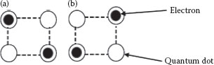
FIGURE 20.1 (a) QCA Cell Logic ‘0’; (b) QCA Cell Logic ‘1’. (P. Wang et al., Minimal majority gate mapping of 4-variable functions for quantum cellular automata, Proceedings of the IEEE NANO, Portland, OR, pp. 1307–1312. © (August 2011) IEEE. With permission.)
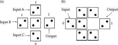
FIGURE 20.2 (a) QCA majority gate (b) QCA inverter. (P. Wang et al., Minimal majority gate mapping of 4-variable functions for quantum cellular automata, Proceedings of the IEEE NANO, Portland, OR, pp. 1307–1312. © (August 2011) IEEE. With permission.)
By forcing one of the three inputs of the majority gate to a constant logic “0” or a “1,” a two-input AND or a two-input OR gate can be realized as shown below.
(20.2) |
(20.3) |
A QCA clock, comprising four distinct periodic phases [19], is needed for both combinational and sequential circuits. The QCA clock performs three main functions. First, the application of clock phases decides the direction of the information flow in the circuit. Second, it provides a mechanism to simultaneously propagate the information through the circuit. Third, it provides the power needed to activate the circuit. The clock controls the tunnel barrier for electrons. If the barrier is low, then the electrons are free to travel through the tunnel; thereby, the QCA cell can be easily polarized by its neighbor cells. If the barrier is high, the tunneling of electrons is not feasible and the QCA cell will hold its polarization state.
The QCA clock works in a pipeline fashion in four clock phases, Switch, Hold, Release, and Relax, as shown in Figure 20.3 [20]. In the Switch phase, the barrier begins to rise slowly and the polarization of the cell is determined by its neighbor cells (which are in the Hold phase). When the cell goes into the Hold phase, the polarization is formed and the barrier reaches its peak. The cell will affect its neighbors to pass on the information. Then, in the Release phase, the barrier begins to lower and the cell may lose its polarization since the binary information has already been passed. Finally, in the Relax phase, the tunneling barrier is in the lowest state, and as a result the QCA cell will remain unpolarized. All the four clock phases constitute one clock cycle, in which one bit information is passed. As the clock continues, the information is propagated through the QCA circuit.
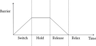
FIGURE 20.3 Four phases of the clock for the QCA circuit.
Using universal logic based on the AND, OR, and NOT functions, any Boolean logic function can be constructed using the QCA majority logic gates and inverters. However, these implementations in general may not be optimal in terms of the number of logic gates or the number of logic levels. With the increasing number of logic levels, the latency of the logic structure increases. Therefore, there is a strong motivation to reduce the number of logic gates and logic levels.
The Boolean logic functions that can be represented by a single majority gate are called primitives. The primitives are the basic units that are used to form all other majority expressions. There are five types of primitives based on the number of input variables to a majority gate. The first type is the trivial case where there are no inputs, that is, a logic “1” or “0,” referred to as a constant-type primitive (“C” type). The second type has a single input variable such as a or c′ and is called a single-type primitive (“S” type). The third and the fourth types of primitives both have two input variables, which are the “AND” type and the “OR” type, respectively. Note that the input variable can appear in the AND and OR expressions as itself or in its complement form. The last type of primitives has all the three variable inputs and is called the “T” type primitive. All these primitives can be realized with one majority gate and their K-map implementations are shown in Figure 20.4.
Since any logic function can be constructed by using primitives, it is important to identify the possible primitives. Let us consider the three-variable Boolean functions. For the first two types, there are eight primitives, logic “1,” logic “0,” single inputs a, b, and c, and their complementary literals a′, b′, and c′. The “AND/OR” type primitives are all based on the two-input majority gates. Therefore, any combination of two inputs from “a,” “b,” “c,” “(a′),” “(b′),” “(c′)” can be used. The combinations that are not allowed are the three pairs, “(a a′),” “(b b′),” and “(c c′).” Each of these combinations appears once for the AND primitive and once for the OR primitive. So, the total number of primitives is given as
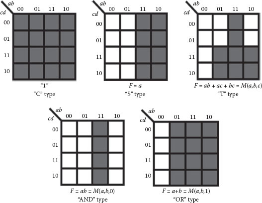
FIGURE 20.4 K-map representation of the five primitive types. (P. Wang et al., Minimal majority gate mapping of 4-variable functions for quantum cellular automata, Proceedings of the IEEE NANO, Portland, OR, pp. 1307–1312. © (August 2011) IEEE. With permission.)
(20.4) |
The “T”-type primitives are based on the three-input majority gates and use all three variables “a,” “b,” and “c.” Each input to the majority gate can appear as itself or its complement, thus giving a total of 23 “T” type primitives. Therefore, the total number of primitives for the three-variable problems is shown as
(20.5) |
Similarly, 90 primitives are possible for the four-variable problem and are shown as
(20.6) |
A partial list of the primitives of the four-variable functions are shown in Table 20.1.
TABLE 20.1
A Partial List of 90 Possible Four-Variable Primitives
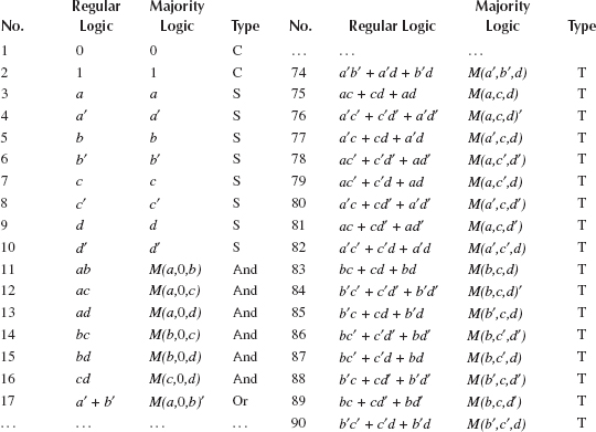
Source: P. Wang et al., Minimal majority gate mapping of 4-variable functions for quantum cellular automata, Proceedings of the IEEE NANO, Portland, OR, pp. 1307–1312. © (August 2011) IEEE. With permission.
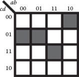
FIGURE 20.5 K-map implementation.
The K-map-based geometric interpretation of the majority gate synthesis method using primitives will be illustrated in this section. Any four-variable Boolean logic function can be mapped to a four-variable K-map. The function, f = ab′c′d′ + abcd+ a′c′d, and its K-map shown in Figure 20.5 will be used as an example to illustrate the synthesis process.
The synthesis solution targeting majority gates will be a tree structure with each of its nodes containing at most three branches representing the three inputs to the majority function. By selecting proper primitives, the top node of the tree gives the synthesis result of the function. Heuristic rules are used in the selection of primitives. The objective of the solution is to cover all the on-set cells using as few primitives as possible. The first primitive should cover as many on-set squares and as few off-set squares as possible. If several primitives can satisfy this rule, one of them is used as the starting solution. The second primitive is selected such that it covers the on-set squares that are not part of the first primitive and does not cover any off-set cells covered by the first primitive. It is also preferred that the second primitive covers as many on-set squares as possible. Once the first two primitives are selected, there are few choices for the third one. It must cover the on-set squares that are covered only once by the first two primitives and it should not cover the off-set squares that are covered once by the first two primitives. In summary, all the on-set cells are covered by at least two of the three primitives and all the off-set cells are covered at most by one primitive. This process yields a solution for the function involving at most four majority gates.
However, not all the four-variable functions could be represented by only three primitives. After the first two primitives are selected, it may not be possible to find a primitive that “will cover the on-set squares that are covered only once by the first two primitives and do not cover the off-set squares that are covered once by the first two squares.” In this case, the required cell coverage should be expanded to another level of majority functions that could be realized with three primitives. As this process is continued, it will lead to a tree-like structure solution for the four-variable logic functions.
Applying this principle to f = ab′c′d′+ abcd+ a′c′d, primitive 79 from Table 20.1 (M(a, c′, d)) is selected first as it covers all the on-set squares and four off-set squares. Then, primitive 4 of Table 20.1, a′ is selected as the second primitive. There is no single primitive that provides the needed pattern cover, shown in the middle K-map of Figure 20.6. Therefore, another level with three primitives is needed to obtain the necessary coverage. A possible solution to obtain the cover for the needed primitive is found as shown in the rightmost three K-maps in Figure 20.6. The solution for the function as shown in Figure 20.6 is f = M(M(a, c′, d), a′, M(M(a, b′, c), M(c′,d′,0), M(b, d, 0))). There may be more than one solution for a given four-variable function. Most of the four-variable solutions can be obtained in three levels of majority gates and all of them can be obtained in four levels.
20.3.3 FOUR-DIMENSIONAL CUBE AND FOUR-VARIABLE K-MAP
A four-variable Boolean function can be represented by a four-dimensional (4-D) cube as shown in Figure 20.7 [21]. Each variable of the function, a, b, c, and d, represents a dimension of a 4-D cube. The 16 different minterms are represented by the 16 vertices in a 4-D cube or by the 16 cells in a four-variable K-map. For example, the minterm abc′d can be represented by a vertex (1, 1, 0, 1) and also as an on-set square in the K-map. For a four-variable function, all the on-set vertices represented by minterms in a 4-D cube can be considered as a certain spatial structure which could be rotated, flipped, or mirrored to represent several other four-variable functions.
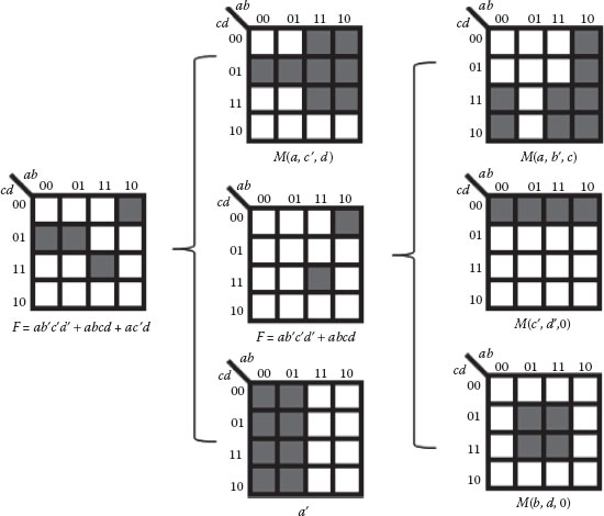
FIGURE 20.6 Solution based on the K-map. (P. Wang et al., Minimal majority gate mapping of 4-variable functions for quantum cellular automata, Proceedings of the IEEE NANO, Portland, OR, pp. 1307–1312. © (August 2011) IEEE. With permission.)
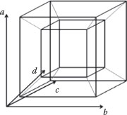
FIGURE 20.7 A 4-D cube. (P. Wang et al., Minimal majority gate mapping of 4-variable functions for quantum cellular automata, Proceedings of the IEEE NANO, Portland, OR, pp. 1307–1312. © (August 2011) IEEE. With permission.)
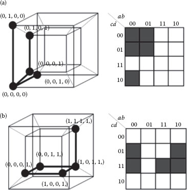
FIGURE 20.8 (a) Interpretation of f = b′d + acd. (b) Interpretation of f= a′c′ + a′b′d′. (P. Wang et al., Minimal majority gate mapping of 4-variable functions for quantum cellular automata, Proceedings of the IEEE NANO, Portland, OR, pp. 1307–1312. © (August 2011) IEEE. With permission.)
As an example, consider two logic functions f = a′c′ + a′b′d′ and f = b′d + acd. After mapping these two logic functions to a 4-D cube and the corresponding K-map, as shown in Figures 20.8a and b, it can be clearly seen that the spatial structures formed by their on-set vertices are exactly the same (one face and another vertex above it), and the only difference is that they are in different locations. If one can find all possible spatial on-set structures for the four-variable functions and determine the simplified majority expressions for each structure, any four-variable problem could be targeted to these solutions to obtain the minimal majority expressions. These structures are referred to as standard functions.
Hamming distance between two minterms is the number of different literals in the two minterms. It is easy to visualize on the K-map as the number of horizontal and vertical steps needed to move from cells representing the minterms. The maximum Hamming distance between two minterms in a four-variable K-map is four. For example, the distance between a′bc′d and ab′c′d is two since the literals involving a and b are different in the two terms. Since the K-map is foldable in both the horizontal and vertical directions, one must be careful in computing the Hamming distance from the K-map.
20.3.5 A METHOD TO FIND STANDARD FUNCTIONS
Hamming distance is utilized to identify all possible standard functions of the four-variable problems. If the Hamming distances between all pairs of vertices in a Boolean logic function are exactly the same as the Hamming distances between all pairs of vertices in another Boolean logic function, then these two functions will have the same structure and can be represented by the same standard function.
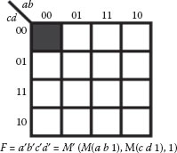
FIGURE 20.9 The standard function with one minterm.
The standard functions are searched based on the number of minterms and the search is limited to at most eight-minterm problems, because Boolean functions with 9–15 minterms can be represented by the complementary function comprising seven to one minterms. The search begins with functions with only one minterm. There are 16 positions for this single vertex in a 4-D cube. No matter which minterm is selected, its spatial structure remains the same on a single vertex. Since the spatial structures are all the same, any one of them could be a standard function. For example, the solution for a′b′c′d ′ is shown in Figure 20.9 as a standard function. Other standard functions with one minterm will have similar solutions except that the inputs to the majority gates will be different.
For Boolean functions with two minterms, there are 15 possible locations where the second minterm can be placed in the K-map as shown in Figure 20.10. Deletion of the structures with similar Hamming distance yields four unique combinations with Hamming distances of one to four as shown in Figure 20.11.
The concept of a distance vector is introduced before continuing to the cases involving three or more minterms. For the four-variable case, the distance vector is a 4-tuple. The first element number represents the number of minterm pairs whose hamming distance is one, the second element represents the number of pairs whose distance is two, the third number represents the number of pairs whose distance is three, and the fourth number represents the number pairs whose distance is four. The distance vectors for the four two-minterm standard function are shown in Figure 20.11. In the figure, the left column denotes the Hamming distances going from one to four, and the right column denotes the distance vector. Since the functions have one pair of minterms, only one of 4-tuples have a value of 1 with the others being 0.
If two functions have the same distance vectors, they are represented by the same standard function. One hundred and forty-three distinct structures are obtained for the 4-variable functions resulting in 143 standard functions. For brevity, a partial list of standard functions is given in Table 20.2. The second column gives the Boolean expression of the function. The third column gives an optimal majority gate implementation. The last column specifies the distance vector for the corresponding standard functions.
20.4 LOGIC SYNTHESIS METHODOLOGY AND IMPLEMENTATION
The flowchart for the proposed majority logic synthesis method is shown in Figure 20.12. The input is an arbitrary Boolean logic function F and the output is an optimal synthesized majority network based on the four-feasible implementations, Gm. The first step of the method is simplifying and decomposing the Boolean function F. A minimized 4-feasible logic network G in which each node contains four or less inputs will be generated after this step. Each node in G is then converted to the corresponding optimal majority expression using the four-variable standard functions and primitives. A preliminary solution is obtained when all the nodes in the 4-feasible network have been converted to majority expression. The solution is then searched to eliminate repeated terms and doubled inversions resulting in a final solution of the majority gate representation, Gm, of the function F.
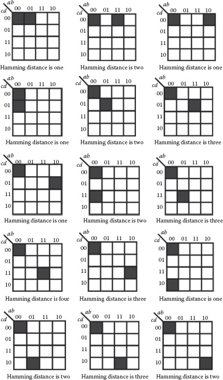
FIGURE 20.10 Process for searching standard functions for two minterm functions.
20.4.1 SIMPLIFYING AND DECOMPOSING
The effectiveness of the proposed synthesis solution depends on the pre-processing of the function F prior to decomposition into the 4-feasible nodes. Pre-processing involves Boolean simplification and algebraic factorization and is performed using the sis tool. The sis pre-processing commands used are given in Figure 20.13. After pre-processing, the network needs to be decomposed to a 4-feasible network. Two approaches are used with a different sequence of sis commands as shown in Figures 20.14 and 20.15. Depending on the function F, one of these two methods results in a 4-feasible function that is better suited to the majority gate synthesis. Therefore, both methods are tried out and given as input to the majority gate converter.
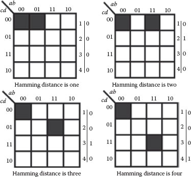
FIGURE 20.11 Four standard functions for two-minterm functions with distance vectors.
TABLE 20.2
Partial List of Standard Functions of Four-Variable Functions
No. |
Standard Functions |
Majority Expressions |
Distance Vector |
1 |
F = a′b′c′d′ |
F = M(M(a′ b′ 0), M(c′ d′ 0), 0) |
None |
2 |
F = a′ ′c′d ′ |
F = M(a′, M(c′ d′ 0), 0) |
1,0,0,0 |
3 |
F = a′b ′c ′d ′+ abc′d ′ |
F = M(M(a′ b′ 0), M(c′ d′ 0), M(a b 0)) |
0,1,0,0 |
4 |
F = a′b ′c ′d ′+ abc′d |
F = M(M(a′ b c′), M(b′ d′ 0), M(a d 0)) |
0,0,1,0 |
5 |
F = a′b ′c ′d ′+ abcd |
F = M{M[M(a′ b′ 0), d′, 0], M[M(a b 0), c, 0], M′ (c, d′ 0)} |
0,0,0,1 |
… |
… |
… |
… |
78 |
F = a′b ′c ′d ′ + a′bc ′d ′ + abc′d ′ + ab′c ′d′ + a′b ′c ′d + a′bc ′d + abc′d |
F = M[M(a′ b c′), M(c′ d′ 0), c′] |
9,9,3,0 |
79 |
F = a′b ′c ′d ′ + a′bc ′d ′ + abc′d ′ + ab′c ′d ′ + a′b ′c ′d + a′bc ′d + a′b ′cd |
F = M{M(a′ b′ 0), M[M(b′ c′ d), a′, 0] 1} |
8,8,4,1 |
80 |
F = a′b ′c ′d ′ + a′bc ′d ′ + abc′d ′ + ab′c ′d′ + a′b ′c ′d + a′bc ′d + abcd |
F = M{M(a′ b′ 0), M[M(a′ c d), M(a′ c′ 0), M(a b 0)], 1} |
7,8,5,1 |
81 |
F = a′b ′c ′d ′ + a′bc ′d ′ + abc′d ′ + ab′c ′d ′ + a′b ′c ′d + a′bc ′d + a′b ′cd ′ |
F = M[M(a′ c′ d′), M(b′ c 0), c′] |
8,9,4,0 |
… |
… |
… |
… |
141 |
F = a′b ′c ′d ′ + a′bc ′d ′ + abc′d ′ + a′bc ′d + a′b ′cd + abcd + ab′cd + ab′cd ′ |
F = M{M[M(a′ b d′), c′, 0], M(a b′ d), c, 0], 1} |
6,12,6,4 |
142 |
F = a′b ′c ′d ′ + a′bc ′d ′ + abc′d ′ + abc′d + ab′c ′d + a′b ′cd + a′bcd + abcd′ + ab′cd ′ |
F = M[M(a c′ d′), M(a′ c′ d), M(a c d)] |
4,12,12,0 |
143 |
F = a′b ′c ′d ′ + abc′d ′ + a′bc ′d + ab′c ′d + a′b ′cd + abcd + a′bcd′ + ab′cd ′ |
F = M(M{M[M(a b d), M(a′ b′ d), M(a′ b d′)], c′, 0},M{M[M(a b d), M(a′ b d′), M(a b′ d′)], c, 0}, 1) |
0,24,0,4 |
Source: P. Wang et al., Minimal majority gate mapping of 4-variable functions for quantum cellular automata, Proceedings of the IEEE NANO, Portland, OR, pp. 1307–1312. © (August 2011) IEEE. With permission.
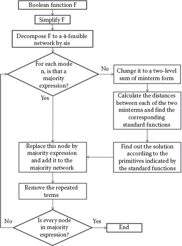
FIGURE 20.12 Flowchart of the proposed method. (P. Wang et al., Minimal majority gate mapping of 4-variable functions for quantum cellular automata, Proceedings of the IEEE NANO, Portland, OR, pp. 1307–1312. © (August 2011) IEEE. With permission.)
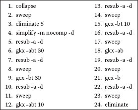
FIGURE 20.13 Commands for Pre-processing. (P. Wang et al., Minimal majority gate mapping of 4-variable functions for quantum cellular automata, Proceedings of the IEEE NANO, Portland, OR, pp. 1307–1312. © (August 2011) IEEE. With permission.)
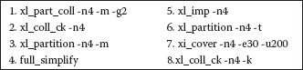
FIGURE 20.14 Commands for the first approach.
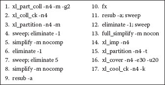
FIGURE 20.15 Commands for the second approach.
20.4.2 CONVERSION TO MAJORITY GATES
After a 4-feasible network is generated, each node in this network is converted to majority expression. A detailed explanation of the conversion is demonstrated using the implementation of the function f = b(a′c′d+ acd′).
Step 1: Simplify the function to the minterm form
This step is illustrated using the K-map and the minterms are mapped to two cells using the following equation:
(20.7) |
Step 2: Calculate the distance of the resulting minterms
The Hamming distance between the two minterms is identified as 3 and the resulting distance vector is (0, 0, 1, 0).
Step 3: Find the corresponding standard function
The standard function 4 in Table 20.1 is found to have the same distance vector as this function, which means they have the same spatial structure and the same type of solution. Therefore, the solution for this problem consists of one “T” type primitive and two “AND” type primitives.
Step 4: Solution targeting the majority gates
As can be seen from Figure 20.16, the “T” type primitive covers both minterms while the two “AND” type primitives cover only one minterm each. The resulting implementation is given as f = M(M(b c d), M(a′ c′ 0), M(a d′ 0)) and its logic diagram is shown in Figure 20.17a. The logic implementation of the same function using MALS described in Ref. [13] is shown in Figure 20.17b.
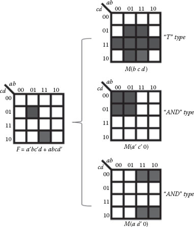
FIGURE 20.16 Solution for f = b(a′c′d + acd′). (P. Wang et al., Minimal majority gate mapping of 4-variable functions for quantum cellular automata, Proceedings of the IEEE NANO, Portland, OR, pp. 1307–1312. © (August 2011) IEEE. With permission.)
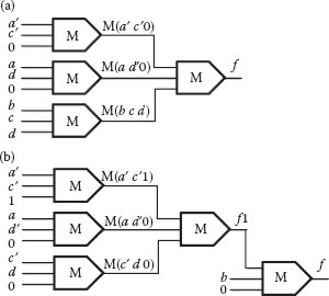
FIGURE 20.17 Majority gate solution using (a) proposed method, and (b) MALS [13]. (P. Wang et al., Minimal majority gate mapping of 4-variable functions for quantum cellular automata, Proceedings of the IEEE NANO, Portland, OR, pp. 1307–1312. © (August 2011) IEEE. With permission.)
The Boolean logic function has already been converted to its majority gate expression. The result can be further simplified by removing redundancies which include repeated terms and doubled inverters. The process of removing is illustrated by an example given below.
(20.8) |
This multi-output Boolean logic network is already a 4-feasible network. The logic functions can be directly converted into majority expression yielding the solution shown below.
(20.9) |
This solution contains two levels of logic and six majority gates, but it can be seen that the terms M(a b 0) and M(c d 0) appear in both functions “f” and “g.” Removing the redundant terms, a simpler solution that uses the four gates is shown in
(20.10) |
The proposed method and MALS are applied to an MCNC/SIGDA benchmark circuit “majority.” The generated results from the two methods are compared, including logic equations, circuit diagrams, and QCA layouts. The logic function of the benchmark circuit “majority” is given below.
(2.11) |
The SIS tool is used to simplify and decompose the circuit to generate a 4-feasible network shown below.
(20.12) |
The proposed method is used to convert each node in the function to its corresponding majority expression. Node f contains two variables, so one-to-one mapping is performed on it. Node (x) contains four variables, so the four-variable standard functions are used to convert this node. Its distance vector is given as (4, 6, 0, 0) and standard function No. 35 is selected. Based on the majority expression for the standard function, the solution for this node contains three levels and five majority gates. The third level is constructed by one “T” type primitive; the second level is constructed by three “AND” type primitives; the first level is also constructed by one “T” type primitive. After all the redundant terms are removed, the final result is shown in Equation 20.13.
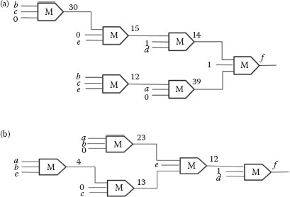
FIGURE 20.18 (a) MALS implementation and (b) implementation of the proposed method.
(20.13) |
The result of the same benchmark circuit benchmark generated by MALS is shown below.
The circuit diagram for the proposed method and MALS are also shown in Figures 20.18a and b, respectively. The proposed method takes one less gate than the existing method, which is a 16.7% reduction.
TABLE 20.3
MCNC/SIGDA Benchmark Circuit Synthesis Comparisons
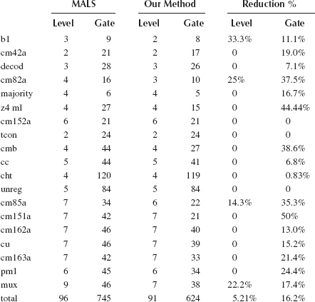
Although the majority gate implementations of all 143 functions are developed, they are not guaranteed to be in the simplest form as the current implementations are based on heuristics developed in the implementations of the standard functions. Still, the proposed method gives better results than the current approaches when applied to several MCNC benchmarks. This synthesis method is currently being integrated with the sis logic synthesis tool. Recently, Kong et al. [15] improved on the 3-feasible function approach of Ref. [13] by performing better decomposition in sis. These approaches will be extended to the 4-feasible functions when the proposed method is integrated into sis.
A comparison of the gate counts and the number of levels for various MCNC benchmarks using the proposed method and the method described in Ref. [13] is shown in Table 20.3. From the table, it can be seen that on average, there is a total reduction of 16.2% in the number of gates and 5.21% in the number of levels using the proposed method as compared to MALS.
As progress is made in nanoelectronic devices, corresponding developments must be made to use these devices in systems applications. Automated synthesis is a key step in this process. This chapter addresses the majority gate logic synthesis targeting QCA applications. A method is proposed for the first time that can handle 4-feasible Boolean networks. A total of 143 four-variable standard functions and their majority gate implementations are presented. This majority gate-based synthesis method is currently being integrated with the sis logic synthesis tool. The primitives are separated into different catalogs, thereby providing a heuristic in searching them rather than using an exhaustive search.
ACKNOWLEDGMENT
This work was supported in part by the National Science Foundation under awards 0958298 and 0958355.
1. International technology roadmap for semiconductors (ITRS). [Online]. Available at: http://www.itrs.net
2. G. L. Snider, A. O. Orlov, I. Amlani, X. Zuo, G. Bernstein, C. Lent, J. Merz, and W. Porod, Quantum-dot cellular automata: Review and recent experiments, Journal of Applied Physics, 85, 8, 1999.
3. C. S. Lent and P. D. Tougaw, A device architecture for computing with quantum dots, Proceedings of the IEEE, 85, 541, 1997.
4. K. G. Walus, A. Jullien, and V. S. Dimitrov, Computer arithmetic structures for quantum cellular automata, Conference Record of the 37th Asilomar Conference on Signals, Systems and Computers, Monterey, CA, pp. 1435–1439, 2004.
5. T. Oya, T. Asai, T. Fukui, and Y. Amemiya. A majority-logic nanodevice using an irreversible single-electron boxes, IEEE Transactions on Nanotechnology, 2, 15–22, 2003.
6. H. A. Fahmy and R. A. Kiehl, Complete logic family using tunneling-phase-logic devices, Proceedings of the International Conference on Microelectronics, State of Kuwait, pp. 22–24, Nov. 1999.
7. S. B. Akers, Synthesis of combinational logic using three-input majority gates, Proceedings of the 3rd Annual Symposium on Switching Circuit Theory and Logic, Chicago, IL, pp. 149–157, 1962.
8. H. S. Miller and R. O. Winder, Majority logic synthesis by geometric methods, IRE Transactions on Electronic Computers, EC-11, 89–90, 1962.
9. S. Muroga, Threshold Logic and Its Applications. New York, NY: Wiley, 1971.
10. R. Zhang, K. Walus, W. Wang, and G. A. Jullien, A method of majority logic reduction for quantum cellular automata, IEEE Transactions on Nanotechnology, 3, 443–450, 2004.
11. M. Bonyadi, S. Azghadi, N. Rad, K. Navi, and E. Afjei, Logic optimization for majority gate-based nanoelectronic circuits based on genetic algorithm, International Conference on Electrical Engineering, San Francisco, USA, pp. 1–5, 2007.
12. S. Rai, Majority gate based design for combinational quantum cellular automata (QCA) circuits, in Proceedings of the 40th Southeastern Symposium on System Theory, New Orleans, LA, pp. 222–224, 2008.
13. R. Zhang, P. Gupta, and N. K. Jha, Majority and minority network synthesis with application to QCA-, SET-, and TPL-based nanotechnologies, IEEE Transactions on Computer-Aided Design, 26, 1233–1245, 2007.
14. Z. Huo, Q. Zhang, S. Haruehanroengra, and W. Wang, Logic optimization for majority gate- based nanoelectronic circuits, International Symposium on Circuits and Systems, Island of Kos, Greece, pp. 1307–1310, 2006.
15. K. Kong, Y. Shang, and R. Lu, An optimized majority logic synthesis methodology for quantum-dot cellular automata, IEEE Transactions on Nanotechnology, 9, 170–183, 2010.
16. E. M. Sentovich, K. J. Singh, L. Lavagno, C. Moon, R. Murgai, A. Saldanha, H. Savoj, P. R. Stephan, R. K. Brayton, and A. Sangiovanni-Vincentelli, SIS: A system for sequential circuit synthesis, Technical Report, University of California, Berkeley, 1992.
17. C. S. Lent, P. D. Tougaw, W. Porod, and G. H. Bernstein Quantum cellular automata, Nanotechnology, 4, 49–57, 1993.
18. C. S. Lent and B. Isaksen, Clocked molecular quantum-dot cellular automata, IEEE Transactions on Electron Devices, 50, 1890–1896, 2003.
19. K. Hennessy and C. S. Lent, Clocking of molecular quantum-dot cellular automata, Journal of Vacuum Science and Technology, 19(5), 1752–1755, 2001.
20. E. P. Blair and C. S. Lent, Quantum-dot cellular automata: An architecture for molecular computing, International Conference on Simulation of Semiconductor and Devices, Cambridge, MA, pp. 14–18, 2003.
21. R. K. Brayton, C. McMullen, G. D. Hachtel, and A. Sangiovanni-Vincentelli, Logic Minimization Algorithms for VLSI Synthesis. Norwell, MA: Kluwer, 1984.
22. P. Wang, M. Niamat, and S. Vemuru, Minimal majority gate mapping of 4-variable functions for quantum cellular automata, Proceedings of the IEEE NANO, Portland, OR, pp. 1307–1312, Aug. 2011.