
Thermally Actuated Nanoelectromechanical Memory A New Memory Concept for Spacecraft Application |
|
CONTENTS
26.3 Buckling Mechanism of Thermal Memory
26.4 Thermal–Structural Simulation
26.5 Geometry Effects on Writing Time and Power Consumption
26.6 High-Energy Particle Collision
Probes used in planetary exploration place greater demands on electronics than terrestrial, or even orbital, systems. The most challenging missions are those that go beyond the orbit of Mars. Because missions to Jupiter’s moons, as well as Saturn and its moons, have been identified as high-priority missions by the National Research Council’s Decadal Survey [1], the development of electronics for these applications is part of NASA’s technology development roadmap [2].
There are three technical challenges in engineering electronics for these applications: low available power, high required reliability, and the need for the configuration to be radiation-resistant. Because missions to the outer planets operate where the solar energy available is much lower than that available on Earth, spacecraft generally rely on radioisotope thermoelectric generators (RTGs). A typical system provides around 500 W, which must satisfy all of the spacecraft’s power needs, including avionics, thermal management, propulsion, and communications [3].
These missions are also of long duration. The journey from Earth to the outer planets requires several years, during which time electronic components may be used in communications with Earth, monitoring spacecraft health, and acquiring data from secondary scientific objectives. Other components may not be used until the spacecraft arrives at its final destination. In both cases, the components must meet higher standards of reliability than terrestrial systems to avoid endangering the success of the mission [4].
The most formidable challenge for spacecraft electronics is the high-radiation environment of space. Deep-space missions remain exposed to high levels of radiation for years. When the spacecraft enters the Jovian environment, the radiation environment becomes even more severe [5], limiting the operational life of a spacecraft in these conditions [6]. There are three major failure modes associated with radiation: total dose damage, latch-up, and single-event upsets. Total dose damage is the deterioration due to the cumulative radiation damage to the material of the device. This can be mitigated by shielding and by materials selection, but still limits the overall life of the system.
Latch-up is a catastrophic failure mode caused by a single high-energy ion causing a thermal runaway in the chip. This can be mitigated by measures such as current sensing and alternate circuit configurations. Because this failure mode is only an issue in powered circuits, it is not the primary concern in nonvolatile memory systems.
The single-event upsets pose the greatest challenge to reliable data storage. A high-energy particle can “flip” a bit that is stored by semiconductor memory, changing a 1 to a 0, or vice versa. This will affect both volatile and nonvolatile memories. Because the spacecraft depends on volatile memories for short-term operations and nonvolatile memories for storing both scientific data and the operating commands of the software, compromised data can affect the ability of the spacecraft to return data and the survival of the spacecraft itself.
In volatile memories, this is usually dealt with by storing data in triplicate and designing the circuit to “vote” on the correct choice. In nonvolatile memories, this is resolved through the frequent use of error codes and rewriting of data. This complication affects the complexity, energy costs, and reliability of the system. These problems can potentially be avoided by using nanomechanical memory as a substitute for conventional systems.
Previous researchers have designed nonvolatile electromechanical memories and volatile mechanical memories operating on the basis of the displacement of bridge structures. The concept of mechanical bistability of a doubly clamped bridge was used to implement these devices [7,8]. A potentially simpler nonvolatile memory device is the buckled-beam nanomechanical memory [9, 10 and 11]. These devices have been electrostatically actuated and successfully demonstrated in laboratory experiments [10], but have not been the subject of extensive performance or reliability analysis.
The optimal design, power requirements, and writing time of buckling-beam-based memories are still not well characterized. These are scientific goals that are necessary for both space-based and terrestrial applications.
This chapter presents a preliminary analysis of a thermally actuated nanoelectromechanical memory mechanism. The mechanism combines thermal actuation with the buckling-beam concept. The simulation of a unit bridge of an array of buckling-beam memory using a finite-difference method gives an overview of how geometry variation affects the power requirements for thermal actuation and writing time of the device.
26.3 BUCKLING MECHANISM OF THERMAL MEMORY
Figure 26.1 illustrates the buckling-beam memory that uses an array of nanofabricated beams and thermal buckling of these devices. Each beam represents a single bit of memory. The data storage density is inversely proportional to the area occupied by each beam, so the ideal array would use the smallest beams possible. The data are then “written” by buckling the beams. A buckled down beam is a “1” and a buckled up beam is a “0.”
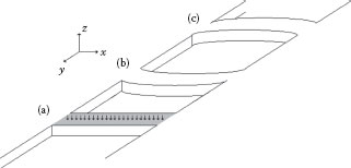
FIGURE 26.1 Nanomechanical memory actuation in a memory array.
Beam (a) is in the initial, unbuckled state. It is being heated, through either a thin-film resistor or a heated tip designed as a writing device, at a constant rate.
After a time tb, the thermal stresses in the axial direction will cause the force in the beam to exceed the force required for buckling from the column stability theory, causing the beam to buckle down as shown in (b). If the heat is added to the bottom of the beam, it will buckle up as (c), which is corresponding to a “0.”
The critical buckling load is defined as follows [12]:
(26.1) |
where E is the modulus of elasticity, I is the moment of inertia, l is the length of the bridge, and κ is the column effective length factor that is equal to 0.5 for both end-fixed bridges.
The thermal force due to thermal stress is as follows [13]:
(26.2) |
where α is the thermal expansion coefficient, T is the temperature distribution, and Tw is the wall temperature (Figure 26.2).
In an ideal case, where there are no losses to the surrounding material or the gas, and the temperature inside the bridge is uniform, Equation 26.2 is simplified as
(26.3) |
where Tb is the total required buckling temperature, and Ac is the cross section of the beam. Tb can be found by combining the formulation for thermal stress inside the beam (Equation 26.3) with the critical buckling load (Equation 26.1):
(26.4) |
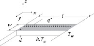
FIGURE 26.2 Simulation geometry.
Using Equation 26.4, the required buckling energy for the ideal case with no losses is obtained as
(26.5) |
where ρ is the density, cp is the specific heat, w is the width, d is the thickness, and l is the length of the bridge. To investigate the nonideal case, there is a need to perform the simulations.
26.4 THERMAL–STRUCTURAL SIMULATION
A simplified model of a beam undergoing thermal buckling is shown in Figure 26.2. The beam is of length l, width w, and depth d, and is at an initial temperature Tw. Depending on how the device is packaged, it may be surrounded by gas molecules at an ambient temperature Ta, and have a convective heat transfer coefficient h. For thermal actuation, the heat load is assumed to be applied on the top of the beam, at a rate of q″ (in W/m2).
As the temperature of the beam increases, the thermal stresses in the beam will increase, and the beam will buckle. To capture this process, the transient heat conduction equation inside the beam must be solved:
(26.6) |
where k is the thermal conductivity of the material [14].
The boundary conditions are based on the thermal conditions at the surface and ends of the beam. There are three different types of boundary condition in this model (Figure 26.2). The Dirichlet boundary condition at both ends is expressed as a constant wall temperature Tw. There are two different types of Nuemann boundary conditions that are applied to heated and unheated surfaces. The boundary condition for the heated top surface includes constant heat flux as well as convective heat transfer while the boundary condition for unheated surfaces only includes the convective heat transfer.
The heat transfer coefficient, h, is calculated based on the free molecular theory for an ideal gas [15]:
(26.7) |
where kb is the Boltzmann’s constant, σT is the thermal accommodation coefficient, γ is the specific heat ratio of the gas, m is the molecular weight of the gas, and ni is the number density of the gas.
For an ideal gas, ni can be calculated using
(26.8) |
where Pgas is the pressure of the gas and R is the ideal gas constant.
The time-dependent temperature field will be used to find the thermal stresses in the beam. When the axial load on the beam is equal to the critical buckling load, the simulated beam is assumed to buckle [16]. The axial load is calculated using Equation 26.2, where T is the nodal temperature distribution.
A finite-difference solver that allows the temperature, materials, ambient conditions, heat load, and geometry to be changed is used to solve these equations. Using these results, a buckling time tb and a total energy for buckling Q for any given geometry and ambient conditions are computed:
(26.9) |
where q• is the total heating rate added to the top:
(26.10) |
26.5 GEOMETRY EFFECTS ON WRITING TIME AND POWER CONSUMPTION
The need to balance the mechanical and thermal properties of both the material and the geometry suggests that this will be an optimization problem. The ideal array would use the smallest beams possible to maximize data storage density. Figure 26.3 shows the buckling time variations versus the dimension variations for silicon bridges. The total heating rate added to the top surface is constant, equal to 99.2 mW. Buckling time variations by the bridge length show that longer structures buckle faster. As the thickness of the bridge increases, the energy consumption increases due to an increase in the moment of inertia (Equation 26.1), leading to an increase in the buckling time. Similarly, an increase in the width leads to an increase in the moment of inertia. As a result, the same behavior as thickness variation is expected to lead to the buckling time increase by the width increase. However, Figure 26.3b shows that the width variations have a less significant effect on buckling time in comparison with the length and thickness variations. Decreasing the thickness and width reduces both energy consumption and buckling time, improving the system’s performance. However, decreasing the length has the opposite effect: increasing energy consumption and buckling time.
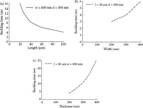
FIGURE 26.3 Buckling time variations by (a) length, (b) width, and (c) thickness variations.
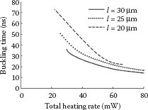
FIGURE 26.4 Buckling time variations by the total heat added to the top surface.
Figure 26.4 shows the buckling time variations versus the total heating rate at the top of the bridge. The thickness d and the width w are constant, equal to 300 and 800 nm, respectively. The buckling time decreases as the total heat added to the top increases. Data storage density is a trade-off. To balance these constraints, a length of 20 μm and the smallest possible thickness and width to fabricate are suggested. The buckling time changes relatively with the length and inversely with the total heating rate.
Figure 26.5 shows the required energy variation with the total heating rate at the top. Longer structures will buckle at lower temperatures, and will require less energy to actuate. They will also have higher convective losses, but lower conduction losses.
Calculations show that for a bridge with a length of 20 μm, a width of 800 nm, and a thickness of 300 nm, the least total energy of 1.58 nJ is required to buckle the bridge. This value is smaller than the estimated one calculated using Equation 26.5 (3.16 nJ). If a ratio of estimated energy divided by calculated energy is defined, it remains constant around 2 for varying heating rates as long as the thickness and the width are constant. Although the required energy to buckle for a beam with constant dimensions is expected to be constant, it decreases slightly as the total heating rate at the top increases. The results show that it is more efficient to increase the heating rate and make the buckling faster. The faster buckling does not increase the losses.
26.6 HIGH-ENERGY PARTICLE COLLISION
These structures will also be subjected to unintentional heat addition. This represents the mechanical equivalent of the single-event upset for conventional semiconductor devices. In the highly radioactive environment of space, high-energy protons and electrons may strike the structure. These particles can be a result of solar events or the planetary environment [3]. To avoid accidental resetting of the spacecraft memory, the beam must be sized so that the energy of the particles does not cause buckling.
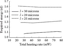
FIGURE 26.5 Required energy versus total heating rate.
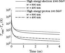
FIGURE 26.6 Heat dissipation after high-energy electron and proton collision for a silicon bridge with a length of 20 μm and a thickness of 300 nm.
The trapped electron and proton energy spectra were previously obtained using the radiation belt models for the Europa orbit of the Jupiter. It shows that the highest energy and the most probable trapped electron and trapped protons carry 1000 and 100 MeV, respectively [5]. If these high-energy particles hit the device and cause undesired buckling, the data will be scrambled. The bridge must be sized to avoid undesired buckling after high-energy particle collision. The worst scenario is that only one particle hits the center of the top surface. The particle is small enough to add instantaneous heat to the central node at the top surface. The amount of this heat depends on the energy the particle carries. The high temperature is calculated assuming that the total energy is transferred to a node.
(26.11) |
where Ehep is the energy of the corresponding high-energy particle, and δx, δy, and δz are the space discretizations in x, y, and z, respectively. The same finite-difference solver is used to investigate the probability of the buckling at the time of collision. The rate of heat dissipation is also calculated.
Figure 26.6 shows the heat dissipation of a bit with a length of 20 μm, widths of 400 and 800 nm, and a thickness of 300 nm, which is hit by the highest-energy electron and proton at the top surface. If buckling occurs, it must be at the very beginning of the collision. The simulation results show that buckling does not occur. In addition, the heat due to the collision dissipates in less than 6 ns, which is much less than the quickest buckling time for the same dimensions, 11 ns (Figure 26.4). Although the rate of heat dissipation decreases by decreasing the width of the bridge, high-energy particle collision will not lead to an undesired buckling in the silicon memory bit.
Thermally actuated nanoelectromechanical memory offers low consumption and rapid write times with a data storage density comparable to existing technologies. The data storage density is a trade-off. Decreasing the thickness and the width is desired for both energy consumption and buckling time. However, decreasing the length has inverse effects. To balance these constraints, a length of 20 μm and the smallest possible thickness and width to fabricate are suggested. The buckling time decreases with increasing the length and the total heating rate.
High-energy particle collision will not lead to undesired buckling in the memory bit. The heat due to the collision dissipates in less than 10 ns, which shows that this memory is highly protective in extreme radiation environment. The resistance to accidental buckling from radiation makes this technology appropriate for spacecraft applications.
1. Committee on the Planetary Science Decadal Survey, Vision and voyages for planetary science in the decade 2013–2022, National Research Council 2011.
2. M. A. Meador, B. Files, J. Li, H. Manohara, D. Powell, and E. J. Siochi, Draft nanotechnology roadmaptechnology area 10, National Aeronautics and Space Administration, November 2010.
3. P. Fortescue, J. Stark, and G. Swinerd, Spacecraft Systems Engineering (Wiley, England, 2003).
4. M. D. Griffin and J. R. French, Space Vehicle Design (AIAA, NJ, 2004).
5. I. Jun and H. B. Garrett, Comparison of high-energy particle environments at the Earth and Jupiter, Radiation Protection Dosimetry, 116(1–4): 50–54, 2005.
6. D. Brown, D. Agle, M. Martinez, and G. Napier, Juno Launch, National Aeronautics and Space Administration, Press Kit, August 2011.
7. T. Nagami, Y. Tsuchiya, K. Uchida, H. Mizuta, and S. Oda, Scaling analysis of nanoelectromechanical memory devices, Japanese Journal of Applied Physics, 49, 044304-1-5, 2010.
8. R. L. Badzey, G. Zolfagharkhani, A. Gaidarzhy, and P. Mohanty, A controllable nanomechanical memory element, Applied Physics Letters, 85, 3587, 2004.
9. B. Hälg, On a micro-electro-mechanical nonvolatile memory cell, IEEE Transactions on Electron Devices, 37, 2230–2236, 1990.
10. D. Roodenburg, J. W. Spronk, H. S. J. van der Zant, and W. J. Venstra, Buckling beam micromechanical memory with on-chip readout, Applied Physics Letters, 94, 183501-1-3, 2009.
11. B. Charlot, W. Sun, K. Yamashita, H. Fujita, and H. Toshiyoshi, Bistable nanowire for micromechanical memory, Journal of Micromechanics and Microengineering, 18, 045005, 7, 2008.
12. S. P. Timoshenko and J. N. Goodier, Theory of Elasticity (Wiley, NY, 1951).
13. B. A. Boley and J. H. Weiner, Theory of Thermal Stresses (Wiley, NY, 1960).
14. F. P. Incropera, D. P. DeWitt, T. L. Bergman, and A. S. Lavine, Introduction to Heat Transfer (Wiley, NY, 2007).
15. M. J. Martin and B. H. Houston, Frequency-dependent free-molecular heat transfer of vibrating cantilever and bridges, Physics of Fluids, 21, 017101, 2009.
16. M. Chiao and L. Lin, Self-buckling of micromachined beams under resistive heating, Journal of Microelectromechanical Systems, 9, 146–151, 2000.