
This chapter discusses the similarities and differences between the various 80×86 processors from the manufacturers AMD and Intel.
Workbench Files:Benchx86chap03projectplatform

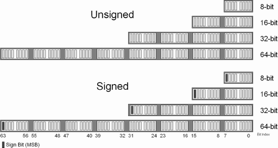
There are a large variety of computers with different processors and different word sizes but there is one constant, the byte. Memory in a computer is represented as a series of bytes and each of these bytes is made up of eight bits. This allows an unsigned value ranging from 0...255 or a signed value ranging from –128...0...127 to be stored in each byte. These eight bits can store one ASCII character A...Z. These bytes can be used together to form larger data structures such as a 16-bit short, 32-bit int, 64-bit long, etc.
In a higher level language such as C this is typically represented by a hex value. For example, 123 decimal is: 64+32+16+8+2+1.
27 128 | 26 64 | 25 32 | 24 16 | 23 8 | 22 4 | 21 2 | 20 1 |
|---|---|---|---|---|---|---|---|
0 | 1 | 1 | 1 | 1 | 0 | 1 | 1 |
So binary 01111011 broken into nibbles (4-bit chunks) 0111 1011 is 7B hex. I did it for you here, but you really should already know how to do decimal-to-hex and hex-to-decimal conversions. In the C programming language this is represented by 0x7B. In an assembler such as MASM this can be represented in a variety of ways:
mov eax, 123                ;Decimal
mov eax, 7bh                ;Hex
mov eax, 01111011b          ;Binary
Let's try that again but with a slightly bigger number in which the most significant bit (MSB) gets set.
27 128 | 26 64 | 25 32 | 24 16 | 23 8 | 22 4 | 21 2 | 20 1 |
|---|---|---|---|---|---|---|---|
1 | 0 | 1 | 0 | 0 | 1 | 0 | 1 |
This maps to 1010 0101 = 0a5h.
It should be pointed out that a number represented in hex in C only needs a leading 0x to indicate that the trailing digits are hex code. In assembly language the suffix of h indicates the value is hex. But if the first digit is not a digit but an alpha value of A...F, then a leading zero is required. Therefore, a hex value in assembly language must always begin with a digit even if it is zero. Letters indicate the word about to be processed by the assembler is a label and not a value! Hex letters A...F can be mixed and matched upper- and/or lowercase; capitalization does not matter.
We are using the value of 0a5h = 10100101B. The B represents binary and the MSB indicated in bold is a 1. If this were an unsigned value ranging from 0...255, then 0a5h would resolve to 128+32+4+1 = 165 decimal. Numbers without prefixes or suffixes are in decimal. But what if this were a negative number? 0a5h is a decimal value of –91. How did we do that? Well, we needed something called a two's complement. This is a one's complement followed by an addition of +1.
Since the MSB is set and this is a signed number ranging from –128 to 127, then first NOT (meaning flip) all the bits in the number.
27 128 | 26 64 | 25 32 | 24 16 | 23 8 | 22 4 | 21 2 | 20 1 |
|---|---|---|---|---|---|---|---|
1 | 0 | 1 | 0 | 0 | 1 | 0 | 1 |
0 | 1 | 0 | 1 | 1 | 0 | 1 | 0 |
The bit sequence of 0101 1010 gives us 5Ah. (Just a coincidence; I chose the 5 and A on purpose since they are complements of each other! Now add 1 to that: 5Ah + 1 = 5Bh = 01011011B = 64+16+8+2+1 = 91. Since we performed the two's complement we also stick the negative sign (–) back on it: – (91), thus –91. Again, this should be review for you but I want to make sure you understand signed versus unsigned values and how to handle one or the other.
Note
To help alleviate any confusion between this book and my vector book, this one was written for multiple processors. Both books share a generic calling convention and a standard naming convention for data types: (b)yte 8-bit, (h)alf-word 16-bit, (w)ord 32-bit, (d)word 64-bit, and (q)word 128-bit.
They are used for function declarations to maintain compatibility between books as well as processor types.
Even though the 80×86 does not use a half-word declaration, I forced it to do so for easier understanding of the vector book. This book is strictly about 80×86 assembly language, and its letter encoding is directly connected to data types and instructions, so the specific 80×86 convention will be used here: (b)yte 8-bit, (w)ord 16-bit, (d)word 32-bit, (q)word 64-bit, and (dq)word 128-bit.
Please keep this in mind if you are switching back and forth between the two books!
A quick history lesson. The 80×86 family started with the 8088 and 8086 (16-bit) processors. These were 16-bit processors as the general-purpose register was 16 bits in size. The 8088, however, had an 8-bit databus. The general-purpose registers had two addressable components, i.e., AX, with the upper 8 bits as AH and the lower 8 bits as AL. Along came the 80186 and 80286. With these came the first foundations of segment:offset addressing. These had a 16-bit segment and a 16-bit offset, which were used to generate a 20-bit address. Thus, there were 12 bits of overlap between the two registers. The segment was used to address a 16-byte block within 1 MB of memory.
The 80386 was the first 32-bit processor to break the 1 MB memory barrier. Additional instructions were added, and the segment:offset registers became selector:offsets. There then became a differentiation between Real Mode using 16-bit addressing and Protected Mode, which used the new 32-bit technology. Then the processor clone wars started between manufacturers. The 80486 came along with additional instructions. The Pentium series came next with the introduction of multimedia instructions known as SIMD with the MMX registers. There were different flavors, different instructions — it was very convoluted and confusing. AMD introduced 3DNow! This is about when the book you are now reading was started. Then came Katmai by Intel, now known as the SSE new instruction set. AMD countered, Intel countered, back and forth. Other manufacturers either sunk at battle or pushed onto the shores of an embedded island. Then the technology was forked by Intel (but we are ignoring the Itanium series in this book). Somewhere along the way AMD and Intel each came out with 64-bit processors and seem to have reached a tentative truce.
Incidentally, the FPU (floating-point unit) was an optional second coprocessor originally known as the 8087 and subsequently the 80187, 80287, 80387, and then the 80487. Back then, floating-point was emulated in software as an alternative if no hardware was present. The FPU grew up with the CPU and eventually become an internal component of the 80486DX CPU. The 80486SX still had to rely upon a coprocessor.
This is as deep into Real Mode as this book is going to get. If you need additional information, please investigate specific documentation from the 80×86 processor manufacturer for your embedded application as Real Mode is fading into obscurity. The same applies to the need for selector manipulation as it can get pretty complicated, but this is only needed by operating system programmers for pre-64 bit processors, and that is not what this book is about. It is written to help those programmers but primarily written for application developers for 32- and 64-bit operating systems. System-level programming pretty much requires its own book about this size.
Many interesting things occurred during the introduction of the Protected and Private Modes. C compilers had to be selected for various code vs. data models.
Model | Code | Data |
|---|---|---|
Huge | 32-bit | 32-bit |
Small | 32-bit | 16-bit |
Large | 16-bit | 32-bit |
Tiny | 16-bit | 16-bit |
Here is a little tidbit before jumping into the details. The 64-bit processor has three operating modes:
These various operating modes give a nice upgrade methodology as well as extend the life of a large portion of pre-existing software as it has the ability to run under the new hardware and operating systems. Additional instructions and hardware have been added to the 32-bit hardware base to enhance its functionality while moving forward into the 64-bit world. I am not going to hype the technology here, as the manufacturers are doing a pretty good job themselves. My job with this book is to help you learn to program in assembly code for 32/64-bit processors. If you are already up to speed with 32-bit, it will help with your transition to the 64-bit machine. At the time of writing this book the new 64-bit operating systems were XP 64 and Linux 64.
At this point you are probably wondering to yourself, "My, this is a small section on the topic for 64-bit processors. Wasn't 64-bit 80×86 in the title?" From this book's point of view its only interest is the hardware capabilities of the instruction set and that means software, not the infrastructure of the hardware. But keep in mind that in 64-bit mode the data size becomes 264.
Tip
264bits are used to store a pretty big number.
A 32-bit unsigned number is 0...4,294,967,295. That is approximately 4.2 GB.
A 64-bit unsigned number is 0...18,446,744,073,709,551,615. That is approximately 18.4 exabytes.
Add computer memory and video memory to get your computer's maximum limit of memory. 64-bit is much higher than 32-bit and should be enough for a couple years of expansion.
That is almost too big most of the time.
for (uint i = 0; i < 7; i++)
For example, in this C for-loop snippet three bits were needed to represent the loop, thus 61 bits are wasted! (Well, not really, but you may begin to see my point.) The advantage to registers that are 64 bits in size is not only can you store a value twice as big as a 32-bit register, but you can address memory that is twice the size. That drastically increases the amount of memory your application can access. Applications can be much bigger! Which means that you can put larger memory sticks into your computers so your computer can run even hotter. (That meant heat, not necessarily speed!) For network applications that is good. But what the chip manufacturers realized is that sometimes those extra bits for size were needed for size of data but mostly not. So this is where things get cool: The default is 32-bit data! The processor stack, however, is still 64 bits.
The topic of 64-bit mode is spread throughout this book. Almost every instruction has a difference when used while in 64-bit mode. Some have been invalidated and thus do not exist anymore. Some have been renamed to help differentiate between 32-bit and 64-bit modes. The one thing to keep in mind is that most use a new 64-bit data addressing scheme involving a REX prefix, which will be discussed later in this chapter. The neat thing is some scalar operations that used to be done with MMX registers can now be done with the general-purpose registers. Instructions that used MMX registers such as PAND, POR, or XOR can now be done alternatively, using 64-bit general-purpose registers in 64-bit mode, thus minimizing the use of MMX registers and alleviating their associated dependency issues.
The goal is to preferably use XMM (SSE) registers or general-purpose registers instead.
So do not feel swizzled! 64 bit is discussed throughout this book!
The Intel 80×86 processor family has internal storage that is referred to as registers. These have been organized into seven groups: general-purpose data registers, segment registers, status registers, control registers, FPU registers used by the FPU (floating-point unit), MMX registers, and XMM registers. Please note that the FPU and MMX registers share storage area and thus are mutually exclusive (only one of them can be used at a time). Each has its own set of functionality.
The following registers and their ranges are for dealing with the SIMD instruction sets directly. They do not include system registers.
The general-purpose registers are organized into two groups of eight registers: The RAX, RBX, RCX, and RDX general registers each have an 8-, 16-, 32-, and 64-bit form, as well as the index registers RSI and RDI, and the stack pointers RBP and RSP. The second set of eight are new registers R8...R15. The instruction pointer RIP has a 16-, 32-, and 64-bit form depending on which mode the processor is running in.
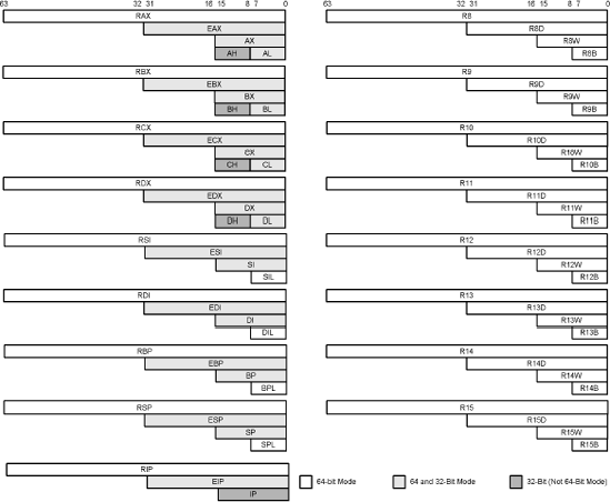
Table 3-3. 64-bit mode registers
64 | RAX | RBX | RCX | RDX | RSI | RDI | RBP | RSP | RIP |
32 | EAX | EBX | ECX | EDX | ESI | EDI | EBP | ESP | |
16 | AX | BX | CX | DX | SI | DI | BP | SP | |
8 | AL | BL | CL | DL | SIL | DIL | BPL | SPL |
64 | R8 | R9 | R10 | R11 | R12 | R13 | R14 | R15 |
32 | R8D | R9D | R10D | R11D | R12D | R13D | R14D | R15D |
16 | R8W | R9W | R10W | R11W | R12W | R13W | R14W | R15W |
8 | R8B | R9B | R10B | R11B | R12B | R13B | R14B | R15B |
Table 3-4. 32-bit (Protected/Real Mode) registers
32 | EAX | EBX | ECX | EDX | ESI | EDI | EBP | ESP | EIP |
16 | AX | BX | CX | DX | SI | DI | BP | SP | IP |
8 | AL AH | BL BH | CL CH | DL DH |
The general-purpose registers are used as memory pointers, address calculations (displacement w/scaling), logical bit, and mathematical operations. There is an exception as the RSP register is the stack pointer and has limitations such as it does not support scaling and displacement. In relation to the segment registers, the 64-bit stack pointer is used in conjunction with the stack segment-selector (SS) register as a default.
Table 3-5. 64-, 32-, and 16-bit general-purpose registers
Register | Extra Functionality |
|---|---|
Note: The "R" prefix of these registers only became available with the 64-bit versions of the processor. The "E" prefix of these registers became available with the introduction of the 32-bit 386 processor. Prior to that, only 16-bit registers were supported. | |
RAX, EAX, AX | The accumulator. If used as a pointer in Protected Mode uses the DS segment register as a default. DS:[EAX] |
RBX, EBX, BX | Used as a data pointer using the DS segment register as a default. DS:[EBX] |
RCX, ECX, CX | Used as a counter in string (rep) and loop operations. If used as a pointer in Protected Mode uses the DS segment register as a default. DS:[ECX] |
RDX, EDX, DX | Input/output port address. If used as a pointer in Protected Mode uses the DS segment register as a default. DS:[EDX] |
RSI, ESI, SI | Source index using DS segment register as a default. DS:[ESI] |
RDI, EDI, DI | Destination index using ES segment register as a default. ES:[EDI] |
RBP, EBP, BP | Pointer to data on the stack (very similar to ESP); uses the SS segment register as a default. SS:[EBP] |
RSP, ESP, SP | Stack pointer used the SS segment register as a default. SS:[ESP] |
RIP, EIP, IP | Instruction pointer. CS:[EIP] |
Regardless of which mode you were in, you could access either 32-bit or 16-bit registers. But this was with the introduction of a pre-op code. If in 32 bit, you accessed 32-bit registers. In 16 bit, you accessed 16-bit registers. But if you needed to access the alternate type, then a hidden leading prefix was embedded in the binary output:
So from 32-bit code...
    mov eax,3
66h mov ax,3
...from 16-bit code...
66h mov eax,3
    mov ax,3
This covers all the 32-bit processors. So now that I have complicated things for you with some history, let us examine the new REX prefix.
The prefix REX is not an instruction, it is an invisible prefix. It is similar to the operand-size and address-size prefix that the assembler and compilers inject into the code when switching before a 16-bit and 32-bit access method. With the new 64-bit instructions it has been extended again.
Note
When the processor is running in 64-bit mode the data is 32 bit. A REX prefix of 40h...48his embedded when using 64-bit data access. After all, a 64-bit number is a very big number and thus not needed that often. Sign extending a 32-bit number when needed is more code efficient.
With the introduction of 64-bit processors a new invisible prefix is used: REX (40h...4Fh). So if this new processor is running in 64-bit mode the previous rules still apply, but to access the 64-bit data a REX opcode is injected:
66h mov ax,3
    mov eax,3
REX mov rax,3Table 3-6. Mappings of inc/dec instructions that use the opcode 40h-4Fh in compatibility or legacy 32-bit mode.
40h | inc EAX |
41h | inc ECX |
42h | inc EDX |
43h | inc EBX |
44h | inc ESP |
45h | inc EBP |
46h | inc ESI |
47h | inc EDI |
48h | dec EAX |
49h | dec ECX |
4ah | dec EDX |
4bh | dec EBX |
4ch | dec ESP |
4dh | dec EBP |
4eh | dec ESI |
4fh | dec EDI |
W | 0 = Default operand size, 1 = 64-bit operand size |
R | Extension of mod r/m register field |
X | Extension of the SIB index field |
C | Extension of the mod r/m field, SIB base field, or opcode reg. field |
The instruction format is a grouping of a prefix that is optional, opcode, mod r/m, sib, displacement, and data. This book does not get into the nitty-gritty of how an instruction, registers, and/or memory references map into an actual opcode. But the bit mapping for the mod r/m is as follows:
Table 3-8. Mappings of mod r/m code. 32-bit is the default. Substitute 16/64-bit for 32-bit form where needed, such as 00-001 DS:[ECX], DS:[CX], [RCX].
MOD | R/M | |
|---|---|---|
00 | 000 | DS:[EAX] |
00 | 001 | DS:[ECX] |
00 | 010 | DS:[EDX] |
00 | 011 | DS:[EBX] |
00 | 100 | s-i-b |
00 | 101 | DS:d32 |
00 | 110 | DS:[ESI] |
00 | 111 | DS:[EDI] |
MOD | R/M | |
|---|---|---|
01 | 000 | DS:[EAX+d8] |
01 | 001 | DS:[ECX+d8] |
01 | 010 | DS:[EDX+d8] |
01 | 011 | DS:[EBX+d8] |
01 | 100 | s-i-b |
01 | 101 | SS:[EBP+d8] |
01 | 110 | DS:[ESI+d8] |
01 | 111 | DS:[EDI+d8] |
MOD | R/M | |
|---|---|---|
10 | 000 | DS:[EAX+d32] |
10 | 001 | DS:[ECX+d32] |
10 | 010 | DS:[EDX+d32] |
10 | 011 | DS:[EBX+d32] |
10 | 100 | s-i-b |
10 | 101 | SS:[EBP+d32] |
10 | 110 | DS:[ESI+d32] |
10 | 111 | DS:[EDI+d32] |
MOD | R/M | |
|---|---|---|
11 | 000 | AL AX EAX RAX |
11 | 001 | CL CX ECX RCX |
11 | 010 | DL DX EDX RDX |
11 | 011 | BL BX EBX RBX |
11 | 100 | AH SP ESP RSP SPL |
11 | 101 | CH BP EBP RBP BPL |
11 | 110 | DH SI ESI RSI SIL |
11 | 111 | BH DI EDI RDI DIL |
There are other mappings but this is sufficient. The reason this book does not get too deep into details is that you are probably not writing assemblers or compilers. If you were, then you mostly would not need this book except as a reference. It is just one of those interesting tidbits but unnecessary for assembly language programming or debugging. "s-i-b" represents (scale-index-base) byte.
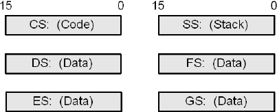
In Protected Mode these registers are referred to as "selectors" and in Real Mode "segment registers." In Real Mode they are used in conjunction with an index register to calculate a memory address. As they are functionally the same, in this section "segment" will mean both. They are sometimes referred to as segment-selectors.
15...0 | Description |
|---|---|
Note: The FS and GS were not available prior to the 386 processor. | |
CS | Code segment |
DS | Data segment |
ES | Extra (data) segment |
FS | Data segment |
GS | Data segment |
SS | Stack segment |
When modifying any segment-selector register you must first save a copy of its stored value and restore it before exiting your function or your program will go "BOOM!" (That is a technical term!) Well, it will not explode as it will just cause the process to crash, but it will sure seem like it exploded. (Ask any assembly language programmer!)
If you are writing a Win32 type application, then typically all the segment-selectors are used in the execution of your code but are usually not denoted in your code as the defaults will be used. The FS and GS are used in your assembly code typically only in device drivers. This is the case of a flat memory model and the DS and ES are set to the same base address in memory. This section essentially becomes a no-brainer! You can completely ignore the segment registers since the DS, ES, and SS are set to the same segment and the indexing registers have used one or the other segment register as a default.
If you are writing an Extended DOS or other OS-based application, then you will typically use most or all of the segment-selector registers, especially in your low-level operating system drivers.
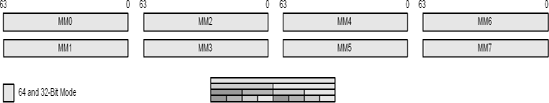
There are eight 64-bit MMX registers (MM0, MM1, MM2, MM3, MM4, MM5, MM6, MM7). These are 64-bit registers that can deal with a single 64-bit number, or two 32-bit, four 16-bit, or eight 8-bit packed values. In the 3DNow! instruction set they used for both integers and floating-point value pairs. These registers were introduced with the Pentium Pro series processors. There are no flags to set or read but based upon the instruction the individual packed data values are treated individually to effectively replicate a desired instruction.
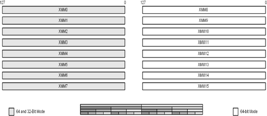
There are eight 128-bit SSE registers (XMM0, XMM1, XMM2, XMM3, XMM4, XMM5, XMM6, XMM7) for pre 64-bit and eight additional registers (XMM8, XMM9, XMM10, XMM11, XMM12, XMM13, XMM14, XMM15) for 64-bit or larger data processors. These are 128-bit registers that can deal with two single 64-bit, four 32-bit, eight 16-bit, or sixteen 8-bit packed values, whether they be integer or single/double-precision floating-point. These registers were introduced with the PIII series processors. There are no flags to set or read, but based upon the instruction the individual packed data values are treated individually to effectively replicate a desired instruction. The functionality of the 64-bit MMX registers was migrated to the 128-bit SSE registers, thus doubling the size but without the burden of the FPU vs. MMX data type switching. Whenever possible, these should be used instead of MMX.
Each 80×86 processor has standard status flags stored in an EFLAGS/ RFLAGS register, which indicate various conditions of the processor. In 64-bit mode the EFLAGS register is referred to as the 64-bit register RFLAGS, with the upper bits set to zero. As this book is written mainly for the application programmer there are only a few EFLAGS that you need to know initially. All the EFLAGS are defined in Chapter 18 but for now:
Table 3-9. RFLAG/EFLAG(s) and bit encoding
EFLAG | Code | Bit | Flag Descriptions |
|---|---|---|---|
EFLAGS_CF | 000000001h | 0 | Carry |
EFLAGS_PF | 000000004h | 2 | Parity |
EFLAGS_AF | 000000010h | 4 | Auxiliary Carry |
EFLAGS_ZF | 000000040h | 6 | Zero |
EFLAGS_SF | 000000080h | 7 | Sign |
EFLAGS_OF | 000000800h | 11 | Overflow |
In this book you will find the following table with each general-purpose instruction description indicating the flags that it sets. Those flags are in reality the individual bits found in the EFLAGS register.
Flags | O.flow | Sign | Zero | Aux | Parity | Carry |
- | - | - | - | - | - |
lahf
The LAHF instruction loads the lower 8 bits of the EFLAGS register into the AH register. This only loads the standard conditional flags used by the Jcc and SETcc instructions. The complement to this instruction is SAHF.
Bit | 7 | 6 | 5 | 4 | 3 | 2 | 1 | 0 |
Flag | SF | ZF | 0 | AF | 0 | PF | 1 | CF |
For more detailed information about EFLAGS, see Chapter 18.
Flags | O.flow | Sign | Zero | Aux | Parity | Carry |
|---|---|---|---|---|---|---|
Flags: None are affected by this opcode. | ||||||
- | - | - | - | - | - | |
This instruction can get you a copy of all the conditional flags in one step without having to use the stack. It should be remembered that only bits {0, 2, 4, 6, 7} are usable and {1, 3, 5} are reserved and not usable.
sahf
The SAHF instruction saves the AH register to the lower 8 bits of the EFLAGS register. This only sets the standard conditional flags used by the Jcc, SETcc, and other instructions. The complement to this instruction is LAHF.
For more detailed information about EFLAGS, see the instruction LAHF and Chapter 18.
Flags | O.flow | Sign | Zero | Aux | Parity | Carry |
|---|---|---|---|---|---|---|
Flags: All flags except overflow are affected by this opcode. | ||||||
- | × | × | × | × | × | |
This can set all the conditional flags in one step without having to use the stack. It should be remembered that only bits {0, 2, 4, 6, 7} are usable and {1, 3, 5} are reserved and not usable.
The PUSHF instruction pushes the lower 16 bits of the EFLAGS register and the PUSHFD instruction pushes the entire 32 bits of the EFLAGS register. PUSHFQ replaces PUSHFD, but it pushes all 64 bits of RFLAGS (the extended EFLAGS). They are the WORD, DWORD, and QWORD forms of the same instruction. (They all map to the same opcode.)
Flags: None are affected by this opcode. | ||||||
|---|---|---|---|---|---|---|
Flags | O.flow | Sign | Zero | Aux | Parity | Carry |
- | - | - | - | - | - | |
To get the EFLAGS, one only needs to push it onto the stack and then pop it off into a general-purpose register!
     pushfd           ; push EFLAGS register
pop eax ; pop those flags into EAXMnemonic | P | PII | K6 | 3D! | 3Mx+ | SSE | SSE2 | A64 | SSE3 | E64T |
|---|---|---|---|---|---|---|---|---|---|---|
POPF |
|
|
|
|
|
|
|
|
|
|
POPFD |
|
|
|
|
|
|
| 32 |
| 32 |
POPFQ | 64 | 64 |
popf | 16 |
popfd | 32 |
popfq | 64 |
The POPF instruction pops the stack value into the lower 16 bits of the EFLAGS register, and the POPFD instruction pops the entire 32 bits off the stack into the EFLAGS register. In 64-bit mode POPFQ replaces the POPFD instruction and pops all 64 bits of RFLAGS. They are the WORD, DWORD, and QWORD forms of the same instruction. This instruction is the complement to PUSHF and PUSHFD.
Flags: All flags are affected by this opcode. | ||||||
|---|---|---|---|---|---|---|
Flags | O.flow | Sign | Zero | Aux | Parity | Carry |
× | × | × | × | × | × | |
Some of the EFLAGS bits can be individually modified by using the PUSHF/PUSHFD and POPF/POPFD CPU instructions. They pop the flags onto the stack, at which point you pop them into a general-purpose register, manipulate the bits, push the register value back onto the stack, and then pop it back into the EFLAGS. This same trick is used to detect CPU capability (see Chapter 16). The same applies to RFLAGS in conjunction with PUSHFQ and POPFQ.
    pushfd                  ; push EFLAGS register
    pop     eax             ; pop those flags into EAX
    xor     eax,EFLAGS_ID   ; flip ID bit#21 in EFLAGS
    push    eax             ; push modified flags on stack
    popfd                   ; pop flags back into EFLAGS
During an interrupt call, the EFLAGS are automatically stored on the stack with the return address so that when the interrupt returns, the register status can be restored to exactly the way it was when the interrupt occurred. The same thing happens in a multithreaded environment. When a thread is preempted so that another thread can be executed for a while, the processor status related to that thread is saved and restored accordingly. This is hidden from the application programmer and so does not need to be worried about. Just keep in the back of your mind that it is taken care of for you.
clc
This general-purpose instruction clears (resets) the Carry flag.
Flags | O.flow | Sign | Zero | Aux | Parity | Carry |
- | - | - | - | - | 0 |
stc
This general-purpose instruction sets the Carry flag.
Flags | O.flow | Sign | Zero | Aux | Parity | Carry |
- | - | - | - | - | 1 |
nop
The NOP is a no-operation instruction. It uses up one instruction byte and changes no flags. It is typically used for code alignment by one byte or a time delay.
Other instructions can be used for nop's of N bytes:
   1    NOP
   1    XCHG EAX,EAX
   3    LEA EAX, {8 disp}
6 LEA EAX, {32 disp}Remember that this is not rocket science, and thus minor deviations will occur in the formulas since, for example, a single-precision float is only 32 bits in size. For higher precision, 64-bit double-precision or 80-bit double extended-precision floating-point should be used instead. These floating-point numbers are based upon a similarity to the IEEE 754 standards specification. Unfortunately the 80-bit version is only available in a scalar form on the 80×86's FPU and the 64-bit packed double-precision is only available on the SSE2 processor.
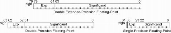
Most programmers only know a floating-point value from using a declaration such as float, double, real4, or real8, etc. They know that there is a sign bit that if set indicates the value is negative and if clear indicates the value is positive. That is typically about the limit of the programmer's knowledge, as floating-point is typically treated as a black box and they typically do not need to dig into it further.
For this book you will be required to understand a little bit more and that will be discussed in Chapter 8.
The 80×86 processor is the most complicated of all the processors due to its life span and constant upgrades and enhancements since its introduction to the marketplace on August 12, 1980. If the 1983 Charlie Chaplin promoter of the IBM personal computer with its 8088 were to see it now he would be proud and astonished at all the architectural changes that have occurred to it over the years.
For a processor to survive it must either be enhanced to meet the demands of technology, find a second life in an embedded marketplace, or die. Intel and AMD have done just that (not the die part), but unfortunately in the process, the technology has forked and so there are now a multitude of flavors of the original 80×86 processor core in existence. In addition, AMD has merged the technologies of the 3DNow! extensions and SSE(2) and formed the 3DNow! Professional instruction sets.
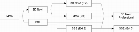
The point is that now there are several 80×86 SIMD feature sets and not all processors have them all. So the first step is to resolve this. Intel initially did so by developing an instruction with the mnemonic CPUID along with a set of sample processor detection code. AMD adopted the same instruction with their set of sample code. As the technology forked further, each company's sample CPUID code emphasized its own processors so programmers have had to merge both companies' code a bit, although AMD's was more diverse. To make it even more complicated, AMD put out 3DNow! Professional. This is a hybrid of all the 80×86 instruction sets of the AMD and Intel technologies, except the SSE (Extensions 3) (at least at the time this book was written). Because of the confusion factor, this book's goal is to try to make it easier to understand.
In Chapter 16 the CPUID instruction is explained. This is a very complicated instruction, but it is wrapped with a function call used by this book that fills in a structure and builds an ASCII string describing the capabilities of a computer in code. It or something similar to it should be used to decide whether a certain set of instructions is usable on a particular computer. Since you are most likely learning this subject material, then you are most likely using one or two computers to test this code and thus know the processor type already. Just to be sure you are running the correct instructions on the correct machine there is a CPUID testing logic included with most of the test applications to run the appropriate set of code. If you wish to learn more about this, please skip ahead to Chapter 16.
void CpuDetect(CpuInfo * const pInfo);
Briefly, the CPU detection code checks for the processor type and its capability and sets flags accordingly. The initialization function attaches function pointers to appropriate code compatible with that processor type and then it is just a matter of the application calling a generic function pointer, which gets routed to the appropriate code.
When you write your code, try to use SSE instructions whenever possible for scalar as well as vector processing. When possible use the instructions that perform quick estimations as they are designed for higher speed calculations despite their lower accuracy. In that way you will always have the best performance for your code, even on newer machines released after you ship your code.
The 80×86 processor has a dual mode in relationship to its MMX and FPU registers. In these particular cases whenever there is a need to switch back and forth, the appropriate instruction needs to be called. In addition, there is a difference between the AMD instruction FEMMS and the Intel instruction EMMS. (These will be discussed in Chapter 8.) When writing code, use instructions that favor using the SSE instructions as the (F)EMMS instructions are only needed if switching between MMX and FPU.
Tip
Note that if your floating-point code gets erratic and appears to have unexpected QNAN or infinity or illegal values, then look for a usage of an FPU or MMX instruction while the other mode was thought to be in effect. It is probably because you are missing an (F)EMMS instruction to flip modes.
The point is that whatever mechanism you put into place — switch-case statements, lookup tables, etc. — you want to have the best (fastest) set of code available for that processor. The trick, however, is not to use up valuable memory supporting all those combinations. Fortunately, consoles such as Xbox are fixed targets, which can assist you in being more selective. In fact, you can get away with absolute function calls rather than function pointers, but that would really be up to you! It all depends upon how you implement your cross-platform capabilities. The code samples use a platform-specific file to connect the dots so to speak, so it can be abstracted out easily to a platform-specific implementation. Of course, if using direct calls you would want to have two flavors of function prototypes in the header files: those set up to be function pointer based and those set up as standard function prototypes.
Another difference between platforms has to do with the format of the assembly instructions. Depending on the processor there are typically two orientations.
Some non-80×86 processors allow the destination register to not be a source register. Thus, Register D = Register A + Register B. Or D = D + A. In C programming this is a form similar to:

The 80×86 processor family requires the destination to be one of the sources. In C programming this is similar to:

One very important processor specification to be aware of is the endian orientation. This drastically affects how byte ordering affects data orientation. Depending on the processor and its manufacturer, data structures larger than a byte are typically arranged in one of two orientations:
One interesting aspect is that for either little or big endian, the 8-bit byte both have an identical bit ordering of bits {0...7}. The MIPS processors (as a default) and the 80×86 are little-endian, but the Motorola 68000 and the PowerPC RISC microprocessor are big-endian.
Little-endian is linear just like memory, so every more significant byte would be the next (incremental) addressed one in memory. For the size of a data word in big-endian, every more significant byte would be the previous (decremental) addressed one in memory.
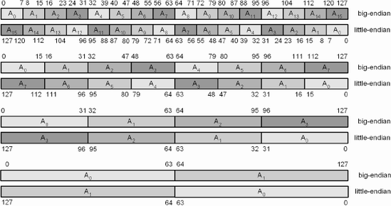
In big-endian the most significant byte is first in memory and it progresses down to the least significant byte; the cycle repeats for the next block. In the following diagram, the data in memory is blocked into groups of 128 bits (16 bytes).
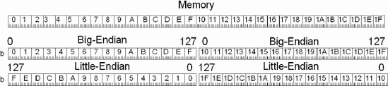
The Intel 80×86 processor is a little-endian based processor. That is, the memory is laid out in a linear fashion so the first byte contains the LSB (least significant bit). For example, as Figure 3-11 shows, a dword has the lower bits (7...0) in the first byte (#0) and bits (31...24) in the fourth byte (#3). This pattern is repeated over and over.
In the C programming language, use the following shift to the left by one for a 32-bit data word (int).
a = a << 1;

Figure 3-11. Visible connections between individual bytes and the left shift of a 32-bit data element
Dealing with endian orientation can sometimes be confusing, especially if you primarily work in little-endian and then need to convert data to the form of big-endian. This makes perfect visual sense for big-endian because the fourth byte contains the least significant bit (LSB) and data is shifted to the left toward the most significant bit (MSB). For little-endian the same shift in C magnifies the value by a factor of two for each bit but visually it makes no sense because the LSB is on the left. By using a mirrored reflection it then becomes clear.
At this point this should be enough conversation about endian orientation of memory until you get to Chapter 6, "Data Conversions," where this is discussed more thoroughly.
In the following little-endian ordered data snippet, you will find an example of the most common data types. The actual hex value is on the right and the byte arrangement in memory is on the left.
0000 12              Ape         db          12h        ; (byte)
0001 34 12           Bat         dw          1234h      ; (word)
0003 78 56 34 12     Cat         dd          12345678h  ; (dword)
0007 F0 DE BC 9A
     78 56 34 12     Dog         dq          123456789ABCDEF0h ; (qword)
Note that the data should be properly aligned to their data type, so a slight rearrangement of the previous data snippet is in order. You should note the previous odd addressing versus the following aligned addressing:
0000 f0 DE BC 9A
     78 56 34 12     Dog         dq          123456789ABCDEF0h ; (qword)
0008 78 56 34 12     Cat         dd          12345678h  ; (dword)
000C 34 12           Bat         dw          1234h      ; (word)
000E 12              Ape         db          12h        ; (byte)
You will note by the base address on the far left that the data has been reordered to ensure that all elements of a data type are properly aligned for their data type. Eight-byte values are aligned on 8-byte boundaries, 4-byte on 4-byte boundaries, etc.
As discussed in the previous chapter, it is very important to have proper data alignment on all data. There are however, times when this is not possible; in those cases the data would still need to be accessed quickly, so before we get into the heavy-duty instructions that can be handled, let us look at a method of handing the pre- and postpreparation of the data for them.
MOV destination, source
mov | rmDst(8/16/32/64), #(8/16/32) | [Un]signed |
mov | rmDst, rSrc(8/16/32/64) | |
mov | rDst, rmSrc(8/16/32/64) |
mov | srDst, rmSrc(16/32) | |||
mov | rmDst, srSrc(16/32) | |||
MMX | movd | mmxDst, mmxSrc/m64 | [Un]signed | 64 |
" | movq | mmxDst, mmxSrc/m64 | " | |
SSE | movups | xmmDst, xmmSrc/m128 | Single-precision | 128 |
" | movups | xmmDst/m128, xmmSrc | " | |
SSE2 | movdqu | xmmDst, xmmSrc/m128 | [Un]signed | 128 |
" | movdqu | xmmDst/m128, xmmSrc | " | |
" | movupd | xmmDst, xmmSrc/m128 | Double-precision | |
" | movupd | xmmDst/m128, xmmSrc | " | |
3DNow! | movq | mmxDst, mmxSrc/m64 | Single-precision | 64 |
lddqu | xmmDst, mSrc(128) | [Un]signed | 128 |
SSE | movaps xmmDst, xmmSrc/m128 | Single-precision | 128 |
" | movaps xmmDst/m128, xmmSrc | " | |
SSE2 | movdqa xmmDst, xmmSrc/m128 | [Un]signed | 128 |
" | movdqa xmmDst/m128, xmmSrc | " | |
" | movapd xmmDst, xmmSrc/m128 | Double-precision |
The instructions do not really move data; rather it "copies" 8-, 16-, 32-, 64-, or 128-bit values from register to register, register to memory, memory to register, and immediate to register or memory, but almost never memory to memory.
Flags: None are altered by this opcode. | ||||||
|---|---|---|---|---|---|---|
Flags | O.flow | Sign | Zero | Aux | Parity | Carry |
- | - | - | - | - | - | |
You will note that these are either a specified floating-point value or a signless "[Un]signed" integer. As the data is being copied, whether or not it is signed has no meaning!
MOV — Copy a (32-bit) double-word value from one location to another. From a 32-bit (4 bytes) general-purpose register to a general-purpose register:
mov eax,ebx // Copy INT32 from register to registerFrom memory to a general-purpose register, or from a general-purpose register back to memory:
moveax,mem32 // Copy INT32 from memory to registermovmem32,ecx // Copy INT32 from register to memory
MOVQ— Copy a (64-bit) quad-word value from one location to another. From 64-bit (8 bytes) memory to an MMX register, or from a MMX register back to memory:
movq    mm0,mem64         // Read INT64 from memory
movq    mem64,mm0         // Write INT64 to memory
For the MMX and SSE the MMX registers can only manipulate integer values. Any kind of data can be loaded but it is treated as an integer whether in reality it is a floating-point value or not. The 3DNow! instruction set, however, does not differentiate.
movq    mm0,mem64         // Read SPFP from memory
movq    mem64,mm0         // Write SPFP to memory
MOVDQU— Move an unaligned double-quad word value from memory to 128-bit memory and vice versa:
movdqu  xmm0,mem128       // Read INT from unaligned memory
movdqu mem128,xmm0 // Write INT to unaligned memoryMOVDQA— Move an aligned double-quad word value from memory to 128-bit memory and vice versa:
movdqa  xmm0,mem128       // Read INT from aligned memory
movdqa mem128,xmm0 // Write INT to aligned memoryMOVUPS— Move an unaligned single-precision floating-point value from memory to 128-bit memory and vice versa:
movups  xmm0,mem128       // Read SPFP from unaligned memory
movups mem128,xmm0 // Write SPFP to unaligned memoryMOVAPS— Move an aligned single-precision floating-point value from memory to 128-bit memory and vice versa:
movaps  xmm0,mem128       // Read SPFP from aligned memory
movaps mem128,xmm0 // Write SPFP to aligned memoryMOVUPD— Move an unaligned double-precision floating-point value from memory to 128-bit memory and vice versa:
movupd  xmm0,mem128       // Read DPFP from unaligned memory
movupd mem128,xmm0 // Write DPFP to unaligned memoryMOVAPD— Move an aligned double-precision floating-point value from memory to 128-bit memory and vice versa:
movapd  xmm0,mem128       // Read DPFP from aligned memory
movapd  mem128,xmm0       // Write DPFP to aligned memory
Keep in mind that the 3DNow! floating-point uses the same MMX registers as the integer instructions and thus this same MOVQ instruction.
For SSE and SSE2, things get a little bit more complicated. The XMM registers are used by the SSE and SSE2 instructions and are used primarily for single-precision scalar or vector floating-point for SSE and both double-precision and 128-bit integer for the SSE2 instructions; they are not interchangeable. There are different memory movement instructions depending on whether or not the memory is aligned. There are other memory load/save instructions other than these, but these are the ones of interest to us in this book.
The functionality for aligned is exactly the same as for unaligned except for one difference. The aligned functions are designed for speed but the memory access must be properly aligned. If the access is misaligned, a processor exception will occur. (The processor execution stops abruptly; aka: Boom!) The penalty for the optimal feature of speed! These instructions were labeled earlier with the declaration "Move an Aligned."
Note
The move instructions in this chapter only demonstrate a same size source:destination move. See Chapter 6 for movements in which source and destination are not the same size.
Data can be moved around using all sorts of methods: immediate to register, immediate to memory, register to memory, memory to register, and register to register, but data cannot be copied from memory to memory, from register to immediate, from memory to immediate, or from immediate to segment register.
Let's begin with immediate values. These are values in C such as A=5. The (5) is an immediate value.
foo dd 0 ; a 4-byte memory location
Copy an immediate value directly into memory:
mov foo,71077345 ; Move directly
Or copy the immediate value into a register and then to memory:
mov     eax,71077345         ; Get the value in decimal
mov     foo,eax              ; Then set it
Or copy it indirectly to memory:
mov     eax,71077345         ; Get the value in decimal
mov     ebx,offset foo       ; Get the address for foo
mov     [ebx],eax            ; Save the value at the address
In all of these examples foo now contains the specified value. All instructions use this sort of destination, source methodology, and I hope you understand that as I am now going to reduce verbosity a tad.
 Out of curiosity, how many of you recognized 71077345 as the old calculator trick of "Shell Oil" upside down? :) (Okay, okay, a little calculator humor!)
Mnemonic | P | PII | K6 | 3D! | 3Mx+ | SSE | SSE2 | A64 | SSE3 | E64T |
|---|---|---|---|---|---|---|---|---|---|---|
XCHG |
|
|
|
|
|
|
|
|
|
|
xchg | rmDst, rSrc(8/16/32/64) | [Un]signed |
xchg | rDst, rmSrc(8/16/32/64) |
8-, 16-, 32-, or 64-bit data can be exchanged between registers of the same size or between memory and a register of the same size. Note that 64-bit exchange is only in 64-bit mode.
The move instruction has a system level functionality where segment/ selector registers can be loaded or set.
If you are developing 32-bit applications the system registers are known as selectors. In Win32 the CS, DS, and ES selectors are typically set to the same block of memory and need not be modified.
If you are developing in Real Mode, aka 16-bit applications, then these system registers are known as segment registers. In the Real Mode environment sreg represents the segment register supporting a 16-bit offset addressing up to a maximum of 65,536 x 16 bytes. In a Protected Mode environment the selector register indexes a 32-bit address using virtual memory. Application programmers do not need to worry about this. In the DOS and Extended DOS Protected Mode environments the ES is typically set to the same value as the DS, and the FS and GS are used to address extraneous memory blocks such as a video graphics adapter (VGA).
Real Mode — An example of an old monochrome write access:
monosel  dw          0b000h

         xor         edi,edi
         mov         es,monosel

         mov         es:[di],ax
         add         di,4
Protected Mode — An example of an old monochrome write access:
monoadr dd           0b0000h
monosel dw           013fh

        mov          edi,monoadr
        mov          fs,monosel

        mov          fs:[edi],eax
add edi,4Memory can be referenced directly using an absolute address like this:
mov eax,MonkeyBrainSoup
or with some displacement. The assembler resolves the address with the offset for a new address:
mov eax,MonkeyBrainSoup+8
This is still an absolute address. The address is simply adjusted and the new address is encoded into the code. If MonkeyBrainSoup were in data memory at location 1000h, then adding the displacement merely would encode the address as 10008h. A structure is referenced in the same way.
vmp3DVector STRUCT
      x       REAL4 ? ;float ?
      y       REAL4 ? ;float ?
      z       REAL4 ? ;float ?
vmp3DVector ends

 MyPos    vmp3Dvector <1.0, 2.0, 3.0>
So addressing this static structure directly:
mov  eax.MyPos.x
mov  ecx.MyPos.y
mov  edx.MyPos.z
really maps to:
mov  eax,DWORD PTR MyPos+0
mov  ecx,DWORD PTR MyPos+4
mov  edx,DWORD PTR MyPos+8
We could address this indirectly by setting ebx to the base address:
mov     ebx,offset MyPos

mov     eax,(vmp3Dvector PTR[ebx]).x
mov     ecx,(vmp3Dvector PTR[ebx]).y
mov     edx,(vmp3Dvector PTR[ebx]).z
Or how about as an array of floats as shown below? Note that 0*4, 1*4, and 2*4 are not addressing multipliers. They are base address multipliers. To truly be a multiplier a register has to be the prefix argument, such as EDX*8 or EAX*2, etc. What the following really says is the base address of 0×1=0 or 1×4=4 or 2×4=8 + the value in ebx = the adjusted base address.
mov  eax,[ebx+0*4]
mov  ecx,[ebx+1*4]
mov  edx,[ebx+2*4]
Or an indexed element of the array:
mov   eax,1           ; Using eax as the element index
mov   ecx,[ebx+eax*4] ; 4 byte float
Those were just some examples, as almost any register can be used alone, in a pair addition, with an optional base address and/or scale factor of {2, 4, or 8}, but note that there are some limitations in regard to the ESP register. For address memory the equivalent scaling factor is needed: int16=×2, int32=×4, int64=×8. During code reviews of other programmers'assembly code I have seen single registers with and without scaling but rarely multiple register addition; instead there is usually some discrete logic to calculate a base address. (That is a waste of CPU time when hardware can resolve some of the addressing for you!)
In regard to the following mapping mechanisms I have read a lot of books and they usually have some minimal reference or simple tables made to show multiple register referencing.
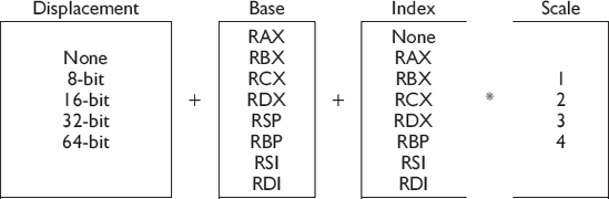
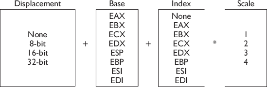
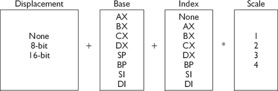
I have never seen them in a verbose table such as that in Appendix C. Even the data books direct from the chip manufacturers seem to be lacking in this information, and so here it is. Seeing it should help you remember and then entice you to use them.
0 | 1 | 2 | 3 | 4 | 5 | 6 | 7 | 8 | 9 | 10 | 11 | 12 | 13 | 14 | 15 |
|---|---|---|---|---|---|---|---|---|---|---|---|---|---|---|---|
1 | 3 | 5 | 7 | 11 | 13 | 17 | 19 | 23 | 29 | 31 | 37 | 41 | 43 | 47 | 53 |
ebx = 0  edx = 1
mov eax, OddTable                ; = 1
mov eax, OddTable[ebx]           ; = 1
mov ecx, OddTable[eax * 4]       ; = 11
mov ebx, OddTable[ebx + ecx]     ; = 37
mov ebx, OddTable[ecx + edx * 4] ; = 53
mov esi, offset OddTable
mov eax, [esi + ebx * 4]
Since the table is 32-bit (4 byte) a multiplier of ×4 can be used to reference the correct array cell. If the table were 16-bit, the multiplier would be ×2, 64-bit then ×8.
The same kind of memory reference used to access an element in a memory table or array can also be used to access a jump or call vector.
Mnemonic | P | PII | K6 | 3D! | 3Mx+ | SSE | SSE2 | A64 | SSE3 | E64T |
|---|---|---|---|---|---|---|---|---|---|---|
LEA |
|
|
|
|
|
|
|
|
|
|
lea | rDst16, mSrc(16/32) | Unsigned |
lea | rDst32, mSrc(16/32) | |
lea | rDst64, mSrc16 |
This instruction calculates the effective address of the source argument and stores it in the destination. It can be used as multi-register math:
mov ebx,2
mov ecx,3
lea eax, [10+ebx+ecx]  ; eax = 10+2+3 = 15
...or a little more indirectly:
lea eax, [10+ebx+ecx*8] ; eax = 10+2+3×8 = 36
An alternate method of lookup simply uses the 8-bit AL register in conjunction with an indirect memory reference for a 256-byte table lookup.
xlat | mSrc8 | [Un]signed |
xlatb |
This general-purpose instruction does a table lookup by adding the AL register to the DS:[eBX] address and copies the selected memory location to the AL register. It is equivalent to the following:
mov     al,[rbx+al]     ; 64-bit Mode
mov     al,ds:[ebx+al]  ; Protected Mode(32-bit)
mov     al,ds:[bx+al]   ; Real Mode (16-bit)
Flags: None are altered by this opcode. | ||||||
|---|---|---|---|---|---|---|
Flags | O.flow | Sign | Zero | Aux | Parity | Carry |
- | - | - | - | - | - | |
If you are building your own logging mechanism for your application and you are not using C where you could use a function similar to:
printf("0x%x", dw);then you will probably want to use the following binary to hex text print algorithm. Or at least some form of it! Okay, I am already breaking rules of precedence where I am using instructions before they are discussed. But bear with me!
HexTbl: db     "0123456789ABCDEF"

;       void HexDmp32(uint32 dw);

HexDmp32  proc  near
         push   ebp
         mov    ebp,esp

         push   ebx

         mov    edx,[ebp+arg1]     ; 32 bits of data

         mov    ebx,offset HexTbl
         mov    ecx,8              ; # of hex lette

$L1:     rol    edx,4              ; MSB ... LSB
         mov    eax,edx
         and    eax,0000000fh      ; mask a nibble
         xlatb                     ; Translate nibble into hex

         call   ChrOut             ; Draw the letter

         dec    ecx
         jnz    $L1                ; Loop for 8 letters

         pop    ebx
         pop    ebp
         ret
HexDmp32  endp
Let's try using an XLATB in a nonsensical state machine mechanism.
; Traverse the state mechanism

State:   db     3, 4, 5, 1, 2, 0ffh

         lea    ebx,State
         mov    al,0

$L1:     xlatb                   ; al = [ebx+al]
         cmp    al,0ffh
         jne    $L1

; at $L1 the AL register will become {3, 1, 4, 2, 5, 0ffh}The following instruction groups LODS, STOS, and MOVS are string functions, which are discussed shortly. An extra instruction REP is used to repeatedly execute a list of data types for a count indicated by the looping count register (CX/ECX/RCX). The register is dependent upon the data-bit mode (16/32/64-bit).
There are additional string instructions not discussed in this chapter. CMPS and SCAS are discussed in Chapter 9, "Comparison." The INS and OUTS instructions are discussed in Chapter 17, "PC I/O." These should be used very carefully. There are alternatives that use register pairing and other methods of optimization. With older processors these were the optimal method of data manipulation but with the newer processors that is not so much the case any more. Loop counters need to be large values to be effective.
Table 3-13. String function and associated index register(s)
Mnemonic | ESI | EDI |
|---|---|---|
CMPSx |
|
|
INSx |
| |
LODSx |
| |
MOVSx |
|
|
OUTSx |
| |
SCASx |
| |
STOSx |
|
Mnemonic | P | PII | K6 | 3D! | 3Mx+ | SSE | SSE2 | A64 | SSE3 | E64T |
|---|---|---|---|---|---|---|---|---|---|---|
LODSx |
|
|
|
|
|
|
|
|
|
|
LODSQ | 64 | 64 |
lods{b/w/d/q} | [Un]signed | |
lods | mDst{8/16/32/64} | |
This instruction reads the contents of memory and loads it into the AL, AX, EAX, or RAX register. It belongs to the group of string functions but it really has nothing to do with text strings in the C sense. It has to do with loading strings of memory, which are contiguous bytes of memory. These functions are equivalent to:
lodsb | lodsw | lodsd | lodsq |
|---|---|---|---|
mov al,ds:[esi] | mov ax,ds:[esi] | mov eax,ds:[esi] | |
inc esi | add esi,2 | add esi,4 |
64-bit mode
lodsb | lodsw | lodsd | lodsq |
|---|---|---|---|
mov al,[rsi] | mov ax,[rsi] | mov eax,[rsi] | mov rax,[rsi] |
inc esi | add esi,2 | add esi,4 | add rsi,8 |
A single read operation can be performed or a repeat sequence specified by a REP prefix word and a count specified in the RCX register in 64-bit mode, the ECX register in Protected Mode, or the CX register in Real Mode.
|
|
|---|---|
|
|
| |
| |
|
|
|
|---|---|
|
|
| |
| |
|
The LOOP instruction could be used instead of DEC and JNE but do not do so, as it is considered complex and actually costs CPU cycles on more advanced model processors. It takes a very special application indeed that does nothing but read a series of bytes into the destination register without processing them. The only result is that only the last data read is remembered! And the source index ESI would point to the next available memory location.
Flags: None are altered by this opcode. | ||||||
|---|---|---|---|---|---|---|
Flags | O.flow | Sign | Zero | Aux | Parity | Carry |
- | - | - | - | - | - | |
Mnemonic | P | PII | K6 | 3D! | 3Mx+ | SSE | SSE2 | A64 | SSE3 | E64T |
|---|---|---|---|---|---|---|---|---|---|---|
STOSx |
|
|
|
|
|
|
|
|
|
|
STOSQ | 64 | 64 |
stos{b/w/d/q} | [Un]signed | |
stos | mDst{8/16/32/64} | |
This instruction writes the contents of the AL, AX, EAX, or RAX register to memory. It belongs to the group of string functions but it really has nothing to do with text strings in the C sense. It has to do with strings of memory. Those single write operations can be performed or a repeat sequence specified by a REP prefix word and a count specified in the RCX register in 64-bit mode, the ECX register in Protected Mode, or the CX register in Real Mode. Those are contiguous bytes of memory. These functions are equivalent to:
32-bit mode
stosb | stosw | stosd | stosq |
|---|---|---|---|
mov es:[edi],al | mov es:[edi],ax | mov es:[edi],eax | |
inc edi | add edi,2 | add edi,4 |
64-bit mode
stosb | stosw | stosd | stosq |
|---|---|---|---|
mov [rdi],al | mov [rdi],ax | mov [rdi],eax | mov [rdi],rax |
inc edi | add edi,2 | add edi,4 | add rdi,8 |
 rep   ins    m(8/16/32), dx
 rep   outs   dx, m(8/16/32)
 rep   movs   mDst, mSrc(8/16/32/64)
 rep   stos   mSrc(8/16/32/64)
 rep   lods   mDst, al
 rep   lods   mDst, ax
 rep   lods   mDst, eax
 rep   lods   mDst, rax

 repe  cmps   mDst, mSrc(8/16/32/64)
 repe  scas   mSrc(8/16/32/64)
Flags: None are altered by this opcode. | ||||||
|---|---|---|---|---|---|---|
Flags | O.flow | Sign | Zero | Aux | Parity | Carry |
- | - | - | - | - | - | |
This function is great for setting a block of memory with a particular value such as for clearing large blocks of memory.
MOVSx
Mnemonic | P | PII | K6 | 3D! | 3Mx+ | SSE | SSE2 | A64 | SSE3 | E64T |
|---|---|---|---|---|---|---|---|---|---|---|
MOVSx |
|
|
|
|
|
|
|
|
|
|
MOVSQ | 64 | 64 |
movs{b/w/d/q} | [Un]signed | |
movs | mDst, mSrc{8/16/32/64} | |
This instruction copies the contents of memory addressed by the DS:[SI], DS:[ESI], or [RSI] source register pair to the ES:[DI], ES:[EDI], or [RDI] destination register pair. It is similar to using both the LODSB/W/D/Q and STOSB/W/D/Q functions except that the AL/AX/EAX/RAX registers are not used. It belongs to the group of string functions, but it really has nothing to do with text strings in the C sense; it has to do with moving strings of memory. This is the only memory-to-memory move. The strings are contiguous bytes of memory. These functions are equivalent to:
32-bit mode
movsb | movsw | movsd | movsq |
|---|---|---|---|
mov al,ds:[esi] | mov ax,ds:[esi] | mov eax,ds:[esi] | |
mov es:[edi],al | mov es:[edi],ax | mov es:[edi],eax | |
inc esi | add esi,2 | add esi,4 | |
inc edi | add edi,2 | add edi,4 |
A single move operation can be performed or a repeat sequence specified by a REP prefix word and a count specified in the ECX register in Protected Mode or CX in Real Mode.
|
|
|
|
| |
| |
| |
| |
|
Flags: None are altered by this opcode. | ||||||
|---|---|---|---|---|---|---|
Flags | O.flow | Sign | Zero | Aux | Parity | Carry |
- | - | - | - | - | - | |
Mnemonic | P | PII | K6 | 3D! | 3Mx+ | SSE | SSE2 | A64 | SSE3 | E64T |
|---|---|---|---|---|---|---|---|---|---|---|
CLD |
|
|
|
|
|
|
|
|
|
|
STD |
|
|
|
|
|
|
|
|
|
|
cld
std
The direction flag is only used by the string instructions to indicate whether the RSI/RDI, ESI/EDI, and SI/DI registers are advanced in a forward or reverse direction. CLD is the norm, where the advance is in a forward (n+1) direction. STD indicates a reverse (n–1) direction.
Flags: None are affected by this opcode. | ||||||
|---|---|---|---|---|---|---|
Flags | O.flow | Sign | Zero | Aux | Parity | Carry |
- | - | - | - | - | - | |
Note
You should avoid the STD instruction as any memory access in a reverse direction is less efficient than in a forward direction, due to memory access cache intelligence built into the processors. It is, however, sometimes necessary to do so for reverse scanning algorithms but should be avoided whenever possible.
To understand these special memory instructions better one first needs to understand some terms:
Temporal data— Memory that requires multiple accesses and therefore is loaded into a cache (as a default) for normal access.
Non-temporal hint— An indicator to the processor that memory only requires a single access (one shot). This would be similar to copying a block of memory or performing a calculation, but the result is not going to be needed for a while so there is no need to write it into the cache; thus the memory access has no need to read and load cache, and therefore the code can be faster!
For more information, see Chapter 18, "System," for more information related to the cache.
SSE | movntdq | mDst128, xmmSrc | [Un]signed | 128 |
SSE | movntq | mDst64, mmxSrc | [Un]signed | 64 |
SSE3 | movnti | mDst32, rSrc32 | 128 | |
EM64T | movnti | mDst64, rSrc64 | [Un]signed | 128 |
The MOVNTDQ instruction copies 128 bits of (non-floating-point) data from xmmSrc to mDst128 using a non-temporal hint.
The MOVNTQ instruction copies 64 bits of (non-floating-point) data from mmxSrc to mDst64 using a non-temporal hint.
The MOVNTI instruction copies 32 bits of (non-floating-point) data from xmmSrc to mDst32 using a non-temporal hint. In 64-bit mode, 64 bits of (non-floating-point) data is copied from a 64-bit general-purpose register rSrc64 to memory destination mDst64 using a non-temporal hint.
SSE | movntps | mDst128, xmmSrc | ingle-precision 128 |
The MOVNTPS instruction copies 128 bits of four (packed single-precision floating-point) elements from xmmSrc to mDst128 using a non-temporal hint.
SSE2 | movntpd | mDst128, xmmSrc | Double-precision 128 |
The MOVNTPD instruction copies 128 bits of two (packed double-precision floating-point) elements from xmmSrc to mDst128 using a non-temporal hint.
maskmovq | mmxSrcA, mmxSrcB | 64 |
maskmovdqu | xmmSrcA, xmmSrcB | 128 |
This instruction copies up to 128/64 bits of memory from xmmSrcA (mmxSrcA) to DS:[EDI] depending on the MSB of each correlating byte in the mask indicated in xmmSrcB (mmxSrcB). If an 8-bit mask element of SrcB has its bit set, then that same correlated 8-bit element of SrcA is copied to the destination memory.
This instruction generates a non-temporal hint to the processor (indicating one-shot data) that it can bypass the cache!
Note that for the MMX instruction MASKMOVQ, the CPU forces a transition from x87 to MMX mode.
   0x12, 0x56, 0x89, 0x23, 0xEF, 0x89, 0x28, 0xC3
   0xE2, 0xFF, 0x04, 0x23, 0x49, 0x41, 0x74, 0x3F
   0x56, 0x89, 0xAA, 0xB2, 0xC7, 0x38, 0x28, 0x2A
   0x28, 0x28, 0x42, 0x73, 0x82, 0xDE, 0xF3, 0x28
Show 128-bit data for SSE in proper endian order, for 8-bit, 16-bit, 32-bit, and 64-bit block sizes.
128 bits = four single-precision floats. How wide would the next generation processor have to be for quad vector double-precision? Write a memory handler for this new hypothetical type processor.
Future super matrix processors will be able to number-crunch entire matrices at a time. How wide would the data path be? Write an alignment macro for that width. Hint: There are two primary solutions!
Earlier in this chapter the function HexDmp32() demonstrated a 32-bit (8 ASCII byte) hex dump. Write a slightly different function that prints a string of 8-bit bytes in hex of a specified count.
void HexDmp(byte *pData, uint nCount);