
Introduction to Max
Welcome to the wonderful world of modeling in Max. This book teaches you modeling; we won’t be touching on animation, materials, or lighting. If you want a more well-rounded treatment, I suggest you pick up a copy of Essential 3ds Max 2008 by Sean McBride (ISBN 1-59822-050-0), available from Wordware.
In this book, I’m going to teach you to model the best way you can: by modeling. We’re not going to spend any time explaining the intimate details of the user interface; we’ll learn what we need when we need it. One of the biggest challenges when learning a 3D package is to not be overwhelmed by the huge number of functions and features.
That said, there are just a few things that you will need to know to start working. That’s what this chapter is for. If you already know the basics, like what a primitive is and how to navigate the user interface, you’re welcome to skip ahead to Chapter 1. However, we will be building a cool bot in this chapter and you might miss something special. You never know. When you’re done with this chapter, you’ll know every tool you need to model anything. All those other tools and widgets, once you learn them, are time-savers and icing on the cake.
 FYI: The product we now know as 3ds Max by Autodesk, Inc. has gone through a number of release versions and name changes over the years, and has also been titled 3D Studio MAX and 3ds max. The current release is 3ds Max 2008.
Primitives and Extended Primitives
Open 3ds Max. If you’re using the default UI setup, your screen should look like this:
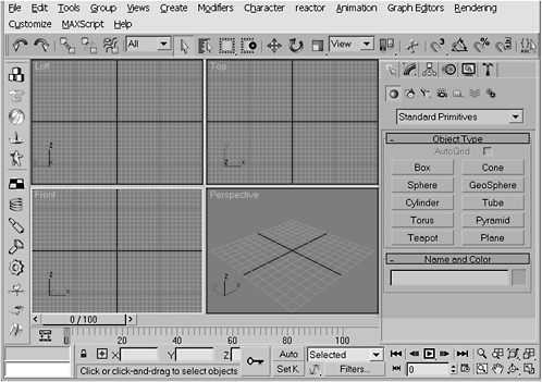
Figure I-1: Default UI layout
FYI: Depending on your screen resolution settings, the toolbars and other UI controls may be located slightly differently.
Don’t worry if you have additional toolbars showing. The only features you need for the exercises in this chapter are the main toolbar and the command panel (as shown in Figure I-1). If your UI does not show the command panel or the main toolbar, not to worry. Pull down the Customize menu, select Show UI, and then check both Show Command Panel and Show Main Toolbar, as shown in Figure I-2.

Figure I-2: Configuring your UI layout
Click on the Perspective viewport and hit the Maximize Viewport toggle button, which is the bottommost icon on the right side of your screen. Alternatively, you can press Alt+W to toggle between maximizing your view and displaying the four orthogonal views.

Figure I-3: Maximize Viewport toggle
Standard Primitives
Look on the right side of the screen. This is the command panel. We’ll be spending a lot of time here. The command panel is composed of subpanels, which are accessible by clicking the tabs at the top of the panel. The default tab (a white arrow pointing to a white asterisk) is the one at the upper left. This is the Create panel, and this is where all projects start.

Figure I-4: The Create panel
At the top of the Create panel is a drop-down list that displays the words Standard Primitives. Primitives are basic 3D computer graphics (CG) forms. CG modeling in 3D is more akin to sculpture than drawing or sketching. Just as a sculptor starts with a block of stone or clay and sculpts a form from it, 3D modeling starts with a primitive and the modeler sculpts an object from it using a variety of tools.
Max provides you with a list of 10 standard primitives, which are listed in the rollout labeled Object Type. Ninety-nine percent of the time, you will only use four of these primitives: box, sphere, cylinder, and torus.
Left-click* on the Box button. Click and hold the left mouse button while dragging anywhere in the Perspective view. When you have a rectangle shape and size you like, release the mouse button and drag up to finish creating a 3D box. Left-click again to release the tool. Voilà! You’ve created your first 3D object.
* From here on out, I will use the term “click” to mean clicking the left mouse button. When I want you to use the right or middle mouse buttons, I will specifically say so.
Do the same thing for each of the primitives. Click on a button and drag in the viewport to create the primitive. Play around a little. I’ll wait.
Your screen should now be a cluttered mess like this:

Figure I-5: Standard primitives
FYI: You may find that your primitives are all different colors. Max automatically assigns colors to primitives unless you specifically tell it not to.
To disable automatic color generation, or to change the color of a particular primitive, click the color swatch in the rollout labeled Name and Color on the Create panel. This opens the Object Color palette. To change an object’s color, either click one of the swatches and click OK or click the Add Custom Colors button to open a standard color picker. To avoid having Max assign random colors, uncheck Assign Random Colors and all primitives drawn will be the color shown in the current color swatch. I personally like a lot of color because it allows me to distinguish the different parts of my model, so I leave Assign Random Colors selected.

Figure I-6
Let’s clean up a bit. Click the Select Object tool, which is the white arrow on the main toolbar (alternatively, you can select this tool by hitting the Q key). Click every object except the box to select them and press the Delete key. That should leave you with just the box. Now click the box (do not hit Delete).
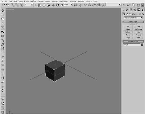
Figure I-7
That box looks far away. Press the Z key. That will zoom and frame the box in the current view.

Figure I-8: Zoomed and framed
Notice the white lines at each corner. This shows you a box primitive is made up of six faces (three you can see and three that you can’t). The F3 key toggles your view between shaded and wireframe modes. Click on the Arc Rotate button at the bottom-right corner of the screen so you can move the mouse to rotate around the object and verify that the box is indeed composed of six faces.

Figure I-9: Wireframe mode and Arc Rotate
Hit F3 to return to shaded mode. Toggling between wireframe and shaded modes is something that you’ll be doing frequently.
Look at the tabs on the command panel. The second tab’s icon looks like a blue rainbow surrounded by dotted lines. This is the Modify panel and the icon, I guess, is supposed to represent a primitive that has been modified using a Bend modifier (we’ll talk about that in a later chapter). Click on the Modify panel tab.

Figure I-10: Modify panel
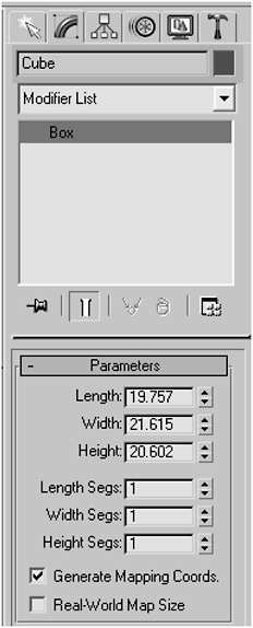
Figure I-11: Changing an object’s name
The Modify panel is where you can very accurately adjust various aspects of an object, such as its name, dimensions, and how many faces it has. To change the object’s name, click in the field containing the name (Box01), highlight Box01 (or whatever Max has called yours), and type Cube. It’s as easy as that! Now change it back to Box01; we don’t actually need to change its name right now.
In the rollout labeled Parameters, you will see three fields representing the dimensions of the cube. Notice that they have up and down arrow buttons next to them. These are called spinners, meaning you can press the up arrow to increase the value in the field or press the down arrow to decrease the value. Personally, I prefer to type in my own values, which you can do as well. Click in the Length, Width, and Height fields and change them to match the values in Figure I-12.

Figure I-12
Throughout this book, I’ll give you the exact values I’m using, so you can get results close to mine. If you’re a free spirit, or simply have problems with authority, that’s fine too; enter whatever values you like. But, if you’re like me, when you’re learning a new skill you want to stick as close to the examples as possible.

Figure I-13
Look below the object dimensions and you’ll see three more fields: Length Segs, Width Segs, and Height Segs. Think of a segment as a line or edge. Adding segments will add faces to your cube. Currently, your cube has six faces. Just as an experiment, change the segment settings to match Figure I-13.
What the -- ? Nothing happened! If your cube didn’t appear to change, trust me … It did. In order to see the change, you have to have edged faces mode turned on. Hit F4.

Figure I-14: Edged faces mode
You should now see the new faces. If you saw the faces, and now you don’t, just hit F4 again. Most “F” keys in Max work as toggles.
FYI: Like in most other programs, the function keys in Max allow you to quickly access commands. The most frequently used keys are F3 to toggle wireframe and shaded modes, F4 to show edges, and F9 to do a quick render of your object.
As you can see from Figure I-14, adding segments in the Modify panel subdivided our original six faces. Again, this is something we will be doing a lot of.
Editable Polygons
Primitives are aptly named because you can’t do anything with them other than add segments and change their dimensions. In order to proceed further in the modeling process, you have to convert the primitive into a form that can be edited: an Editable Polygon.
To convert an object to an Editable Polygon, right-click on the object, choose Convert To, and select Convert to Editable Poly.
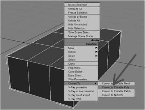
Figure I-15: Convert to an Editable Polygon
Nothing much seems to have changed, but if you look to the right you’ll see that the controls on the Modify panel have changed. Not only is there a brand new set of selection tools available to you, but you now have a set of editing or modeling tools you can use to sculpt the object.
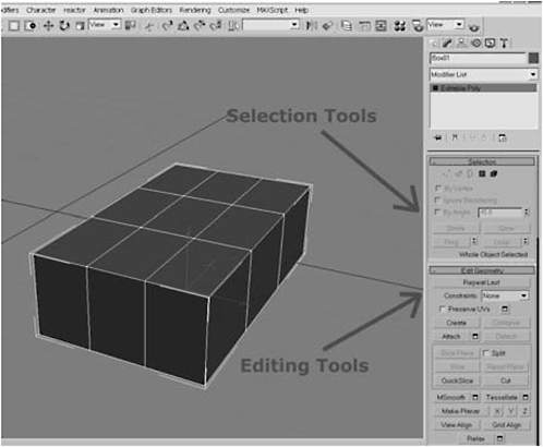
Figure I-16: The Modify panel has more tools when an Editable Polygon is selected.
Once you convert an object to an Editable Polygon, the faces of the object are composed of four vertices (or points). Two vertices, when connected, create an edge. Four connected edges create a face. Editable objects are created by faces.

Figure I-17: Editable Polygon structure
3D modeling is nothing more than moving edges, faces, and vertices to form new shapes.
Day 1: Building a Simple Bot
Okay, using the same box we’ve been practicing on, we’re now going to create a bot similar to the B9 from the old TV show Lost in Space. To make it easy to follow along, I’m dividing the material into discrete steps (so you can stop to take a break when necessary or grab a frosty beverage of your choice :-) ).
1. In the Selection rollout of the Modify panel, click the Edge selection mode button, then hit the F3 key to switch to wireframe mode (to better see what you’re doing). Now hold down the Ctrl key and click on the top three edges on the front and back of the object.
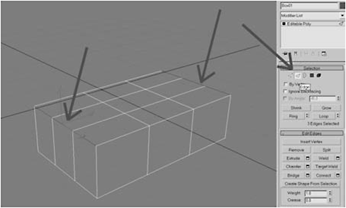
Figure I-18: Select edges
2. In the Edit Edges rollout, click the Chamfer Settings button (the square button to the right of the Chamfer button). Enter 5.0 for the Chamfer Amount and then click OK.
FYI: Chamfer, like Loft and Lathe, is a function that takes its name from woodworking. To chamfer means to cut off a corner or edge to create a bevel. In Max, you can chamfer vertices, polygons, and edges.
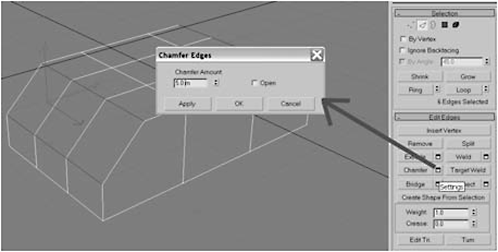
Figure I-19: Chamfer settings
2008 Version! To the frustration of modelers, nearly all the changes in the 2008 version of Max are changes in workflow compatibility with other Autodesk products. There are very few changes to the actual modeling tools, and those changes are just tweaks. Chamfer is a good example. In the 2008 version, the Chamfer function now has a spinner that allows you to enter multiple edges and saves you from having to do multiple chamfers to round an edge.
FYI: There are two ways to use a given tool. You can either click the tool button or click the Settings button to its right. If you click the tool button, you then click and hold the left mouse button while dragging the mouse to use the tool, making changes by eye. Clicking the Settings button opens a dialog box where you can enter an exact value. Many modelers who are artists prefer to click the tool button and use the mouse to manually sculpt the object. I prefer entering exact values with the Settings button. For the purposes of this book, I’ll use the Settings button so you can more easily follow along.
FYI: A word about polygons. An ideal polygon has four edges, created by four linked vertices. Sometimes, as happened when we chamfered, you can end up with a polygon that has more than four sides. This can cause you trouble later, such as when you try to use smoothing. It’s good practice to turn polygons with more or less than four sides into four-sided polygons.

Figure I-20: Four-sided vs. five-sided polygons
3. Hit the L key to switch to the Left viewport, hit the Z key to zoom and frame the object, and then click the Edge selection mode button to turn off the tool.

Figure I-21: Turn off edge selection
4. Click the Polygon selection mode button and then hold down the left mouse button and marquee-select the front faces of the model.
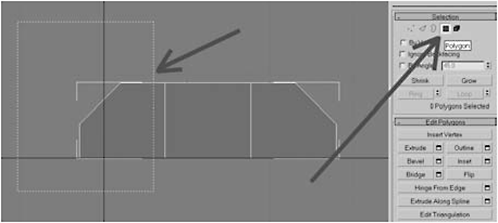
Figure I-22: Select the front faces
5. The polygons turn red to indicate they’ve been selected. In the Edit Geometry rollout, click the Slice Plane button. The slice plane appears on the screen as a yellow line. Currently, however, it is facing the wrong direction. Rather than being horizontal, it should be vertical.
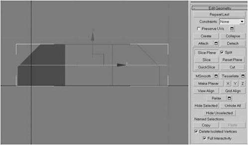
Figure I-23: Using Slice Plane
FYI: The Slice Plane tool uses a plane (a two-dimensional rectangle) to create a perfectly straight cut through all the faces it intersects. We’ll be using it to fix the five-sided polygon problem.
6. Hit the E key to activate the Select and Rotate tool (the gizmo shows as multicolored concentric circles that appear at the pivot point of an object or tool).

Figure I-24: Select and Rotate tool
FYI: Gizmo? Yeah, it’s a pretty dumb name. Gizmo is Max’s generic term for a manipulator. The gizmo’s shape tells you what type of manipulation it does. Circles mean rotate, crossed arrows mean move, and arrows connected by a triangle mean scale (i.e., resize).
The manipulate tools (select, scale, and rotate) have two modes like the modeling tools. You can select them and then click and hold the left mouse key while moving the mouse. Or you can right-click on the button on the main toolbar to open a dialog box for entering exact values.
7. Right-click the Select and Rotate tool to open the dialog box and enter 90 in the Offset Screen Z field to rotate the slice plane 90 degrees on the Z axis.

Figure I-25: Rotate Transform dialog box
8. Hit the W key to activate the Select and Move tool (hereafter referred to as the Move tool). Click and drag the mouse to move the red X axis arrow to the left (to move the slice plane in the X axis only), until the slice plane is positioned as shown in the following figure.
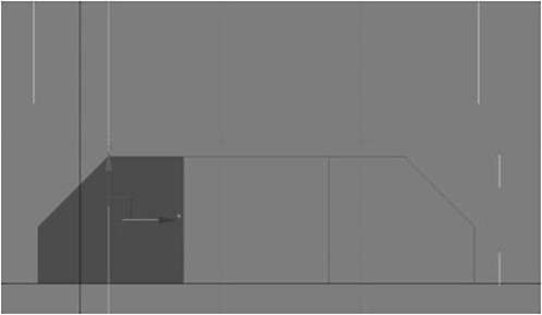
Figure I-26
9. As you might guess from looking at Figure I-26, strategically placing a cut here will resolve our five-edged polygon problem. Well… at least in the front. Click the Slice button to slice the polygons beneath the slice plane.
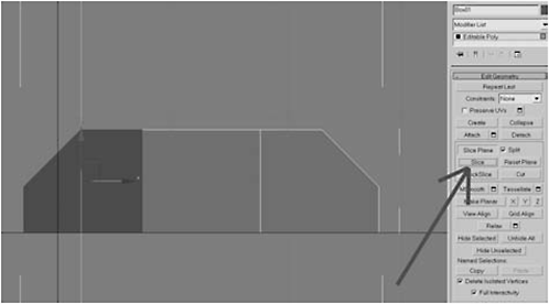
Figure I-27
10. Click the Slice Plane button again to turn it off and then marquee-select the matching polygons in the rear. Note that the front faces have been cut, turning the five-sided and four-sided polygons into two four-sided polygons.

Figure I-28
11. Click the Slice Plane button to reactivate it, hit the W key to activate the Move tool, drag it in the X axis to position it as shown in Figure I-29, then click the Slice button. Click the Slice Plane button again to turn it off.

Figure I-29
12. Hit the Q key to activate the Selection tool. Click anywhere in the gray area, except on the object, to deselect the polygons.
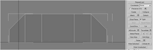
Figure I-30
 Fire Drill: You may have solved the five-edged polygon, but possibly created another problem for yourself. Unless the slice plane is exactly positioned over the top vertices, the slice may create a row of polygons very close to the top row. So close it’s hard to see. This extra row will create a sixth face. So it’s good practice when doing this sort of operation to use the Weld tool to weld any errant vertices together. If there are no errant vertices, the Weld tool won’t do anything. However, if you have accidentally made some extra vertices, the Weld tool will fix it.
13. Marquee-select the top-left vertices.

Figure I-31

Figure I-32
15. Click the Weld Settings button and set the Weld Threshold to 0.01. If there aren’t any overlapping vertices, the Before and After numbers will be equal. Since there should be three edges on the front (six vertices) and three edges on the back (six vertices), if the slice plane has created new vertices that number should be double, or 12. This means the After value should be 12 less than the Before value (meaning that 12 vertices will be welded together).

Figure I-33: Weld vertices
16. Click OK to weld the vertices. You’ve solved the five-edged polygon problem.
17. Hit the F key to go to the Front view and hit the F3 key to toggle from wireframe to shaded. If the edges aren’t showing, hit the F4 key to show the edges.
18. Click the Polygon selection mode button and marquee-select the leftmost polygons. Then, holding down the Ctrl key, marquee-select the rightmost polygons.
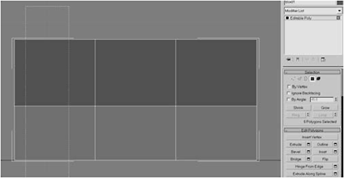
Figure I-34
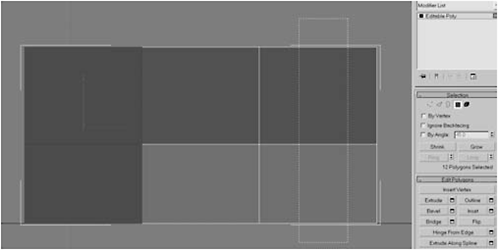
Figure I-35
19. Hit the P key to switch to Perspective view. Click the Arc Subobject Rotate tool, then click and hold the mouse and move the mouse to orbit the view around the model until you get an approximation of the view shown in Figure I-36.
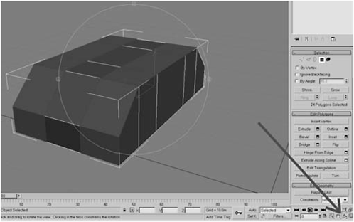
Figure I-36
FYI: There are three flavors to the Arc Rotate tool: Arc Rotate (top), Arc Rotate Selected (middle), and Arc Subobject Rotate (bottom). Arc Rotate rotates the view around an imaginary center of all the objects in the scene. Arc Rotate Selected, as its name implies, rotates around the selected object. Arc Subobject Rotate, the method we'll use most often, rotates the view around the selected subobject (vertex, edge, polygon).
FYI: Introducing: Bevel, the wonder tool! The Inset tool takes existing faces and creates a smaller set of faces within them. The Extrude tool takes existing faces and grows them either outward or inward, depending on the Height value. Bevel combines both tools into one, making Inset and Extrude all but unnecessary. It has three settings: Type, Height, and Outline. Setting the Height and the Outline allows you to inset (or outset) and extrude simultaneously. Only want to extrude? No problem! Set the Outline amount to 0, then set the Height, and it works like Extrude. Only want to inset (or outset)? Set Height to 0 and enter a positive number for Outline amount to outset, or a negative number to inset.


Figure I-37

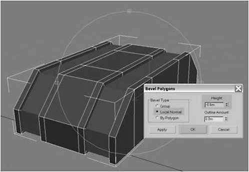
Figure I-38
FYI: Why switch Bevel Type from Group to Local Normal? Local Normal refers to the direction a face is pointing. When Group is used, all the polygons are moved or scaled in the same direction. When Local Normal is used, each polygon is moved in the direction it’s facing.
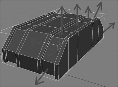
Figure I-39: Local normals
21. Open the Create panel, select Box, check AutoGrid, and create a box with these settings:
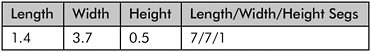
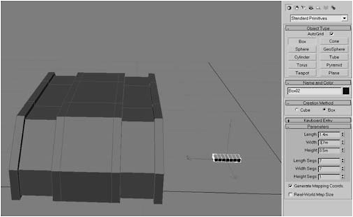
Figure I-40
22. Let’s make some tracks! Hit the Z key to zoom and frame the box you made, then right-click and choose Convert To > Convert to Editable Poly.
Figure I-41
23. Select the four polygons shown below and then click the Bevel Settings button. Apply these settings:


Figure I-42

Figure I-43
24. Click the Arc Subobject Rotate tool (bottom right) and rotate around the back of the box. Select the three polygons shown in Figure I-44, and apply these settings:

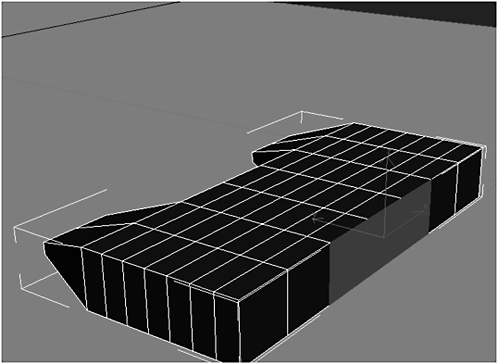
Figure I-44

Figure I-45
25. To make the tread on the track segment, select the polygons shown highlighted below on the top of the track segment (nothing special about the pattern, so feel free to use your own).

Figure I-46


Figure I-47

Figure I-48
27. Click the Polygon selection mode button again to turn it off, select the body, click the Edge selection mode button, select one of the edges inside the recessed area, and then click the Loop button. (Note: This is easier to do if you toggle wireframe (F3).)
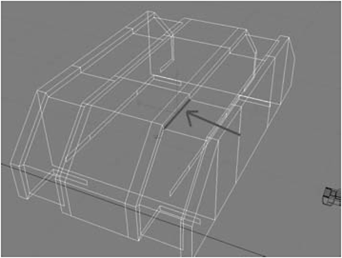
Figure I-49

Figure I-50
28. In the Edit Edges rollout, click the Create Shape From Selection button, type track for the object’s Name, click Linear, and then click OK.
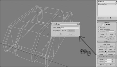
Figure I-51
FYI: Create Shape From Selection is one of the most deceptively powerful tools in your Max arsenal. It will take any selection and turn it into a spline, or path. The spline itself is not renderable (unless you specifically tell Max to render it, which we’ll do in a later chapter). But it can be very handy in creating a path for other geometry to follow. In this case, the spline will form the basis for our tank track.
29. If you haven’t done so yet, select the track object you made in steps 22-26, and rename it tread by typing in the field at the top of the command panel, as shown in Figure I-52.

Figure I-52
30. Hit the H key and select track from the list, right-click on the Scale tool, and scale the path to between 105% and 115%, or until the path is above and below the edges of the body. Make sure the track is not touching or intersecting the base and is about equidistant from the base on both the top and bottom (use the Move tool if necessary).
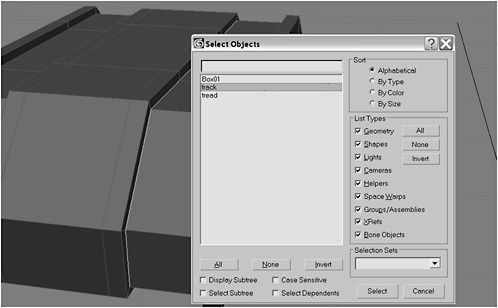
Figure I-53

Figure I-54
Fire Drill: This is one of those things that’s hard to get right the first time out. It really does take a couple of attempts. In the steps that follow, we’ll be using the shape as a guide for arranging clones of the tread into a tank tread. However, once the clones are made, their arrangement can be altered by altering the size and shape of the path. So generally, you take your best guess, generate, and arrange the clones. If their arrangement doesn’t suit you, edit the path (e.g., scale the shape) and the clone arrangement will automatically be adjusted. So… once you’ve made your clones, don’t delete the shape until you’re certain you’re done with it.
31. Hit the W key and center the track in the groove, then select the tread object.

Figure I-55

Figure I-56
32. From the main toolbar, select the Tools menu, then select Spacing Tool. When the Spacing Tool dialog box opens, click the Pick Path button, hit the H key, select track, and then click Pick.
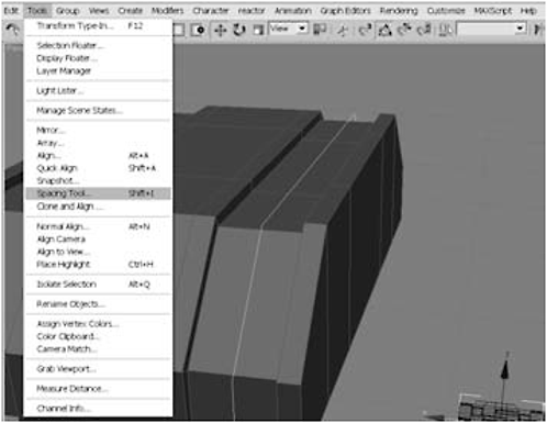
Figure I-57
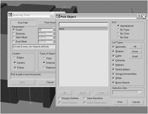
Figure I-58
33. In the Spacing Tool dialog box, click Count and type 34 for the number of clones. In the drop-down list in the middle of the dialog box, select Divide Evenly, No Objects at Ends, set the context to Centers and enable Follow, select the type of object to be Instance, and click Apply. Then close the dialog box. You’ve just made 34 tread objects we’ll call “links.”
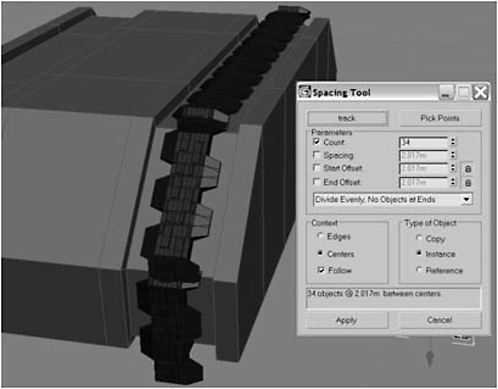
Figure I-59
FYI: The settings relate to how the objects (tread links) will be arranged. Count specifies the number of tread links on our track. The drop-down list tells Max to evenly space each link. Think about a tank track. Are the treads not evenly spaced? As for that No Objects at Ends bit… that means the last link will be left off so you won’t have any overlapping. Context tells Max how to space them (from the center of each link).
 Urgent: While the track looks cool, it’s not really what I had in mind. The single extrusion is meant to slide between the dual extrusions, so we’ll have to fix that by rotating the orientation of the tread link.
34. Press Ctrl+Z to undo the last step, then select the tread link, right-click the Rotation tool on the main toolbar, and enter 90 for the Absolute World Z axis. Repeat steps 32 and 33 to recreate the track.

Figure I-60

Figure I-61
Fire Drill: Now the tread is arranged the way it’s supposed to be. However, you’ll still have to tweak some of the links manually. The Spacing tool is not a perfect solution. It saves you a lot of heavy lifting, but expect to do some tweaking to get the look you want.
35. Select the tread link, right-click, and select Hide Selection to hide the tread. Then hit the H key and select all 34 tread objects.

Figure I-62

Figure I-63
36. Hit the W key to select the Move tool, then hold down the Shift key and drag in the X axis (left). When the Clone Options dialog opens, click Instance to create an Instance clone of the track in the left groove. Hit the H key and select Box01.

Figure I-64

Figure I-65
37. Rename Box01 to base, click the Attach List button (the box to the right of the Attach button), select all the tread objects, and click the Attach button.

Figure I-66
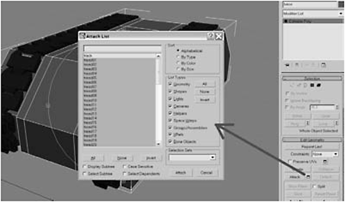
Figure I-67
38. Hit F9 to do a test render.
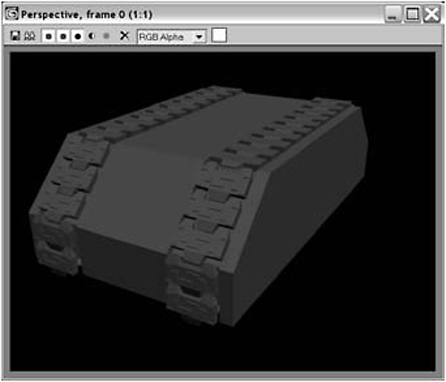
Figure I-68
39. Select the polygon in the middle of the base and then click Bevel Settings. Enter the following values for the bevel:

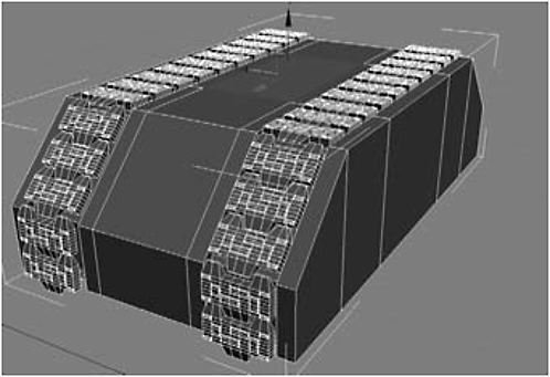
Figure I-69

Figure I-70
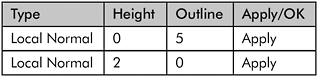

Figure I-71

Figure I-72

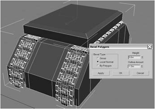
Figure I-73
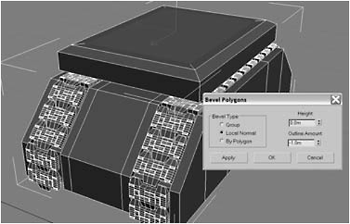
Figure I-74
40. Select the polygon, right-click the Scale tool, select Non-uniform Scale (the middle icon), and type 70 for the Offset World Y axis.
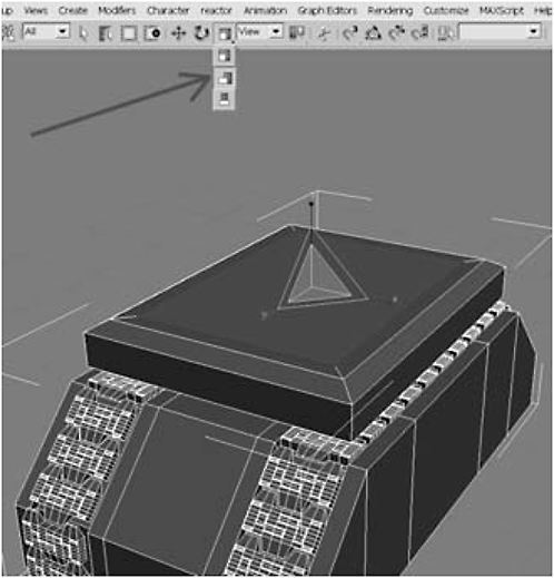
Figure I-75

Figure I-76
41. Extrude the polygon –1.0.
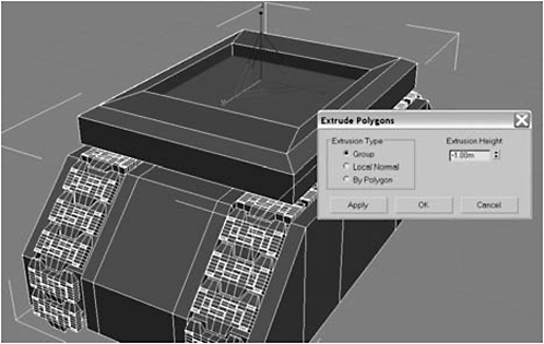
Figure I-77
42. Hit the T key to switch to the Top viewport, choose AutoGrid ,and create a Cylinder in the indentation you just created with the extrusion. Then right-click and select Convert to Editable Poly. Use the following values for the cylinder:
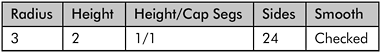

Figure I-78

Figure I-79
43. Shift-drag to create an Instance clone and position it as shown.
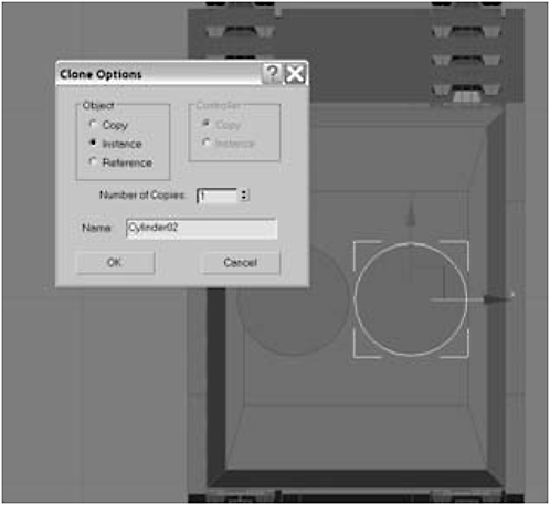
Figure I-80
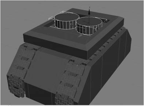
Figure I-81
44. Click Attach List and attach the second cylinder to the first. Then select the six middle facing polygons on each cylinder and delete them.
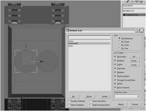
Figure I-82

Figure I-83
45. Click the Border selection mode button and then click the borders created by the deletion of the polygon. Under Edit Borders, click the Bridge Settings button to bridge the gap and create new geometry.
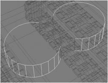
Figure I-84

Figure I-85
46. Click the Polygon selection mode button, then polygon-select all the polygons on top, delete them, and border-select the resulting border.
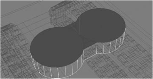
Figure I-86

Figure I-87
47. Press the Cap button to cap the border. Select an edge on the top and bottom and then click Loop to select the top and bottom edges.

Figure I-88

Figure I-89
48. Click the Chamfer Settings button, chamfer the edges by 0.12, and then click Apply. Chamfer the edges again by 0.04 and click the Apply button.

Figure I-90
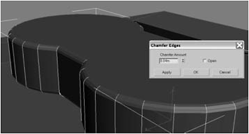
Figure I-91
49. Chamfer the edges one more time, by 0.02, and click OK. Now select the top.
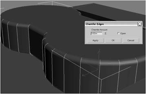
Figure I-92
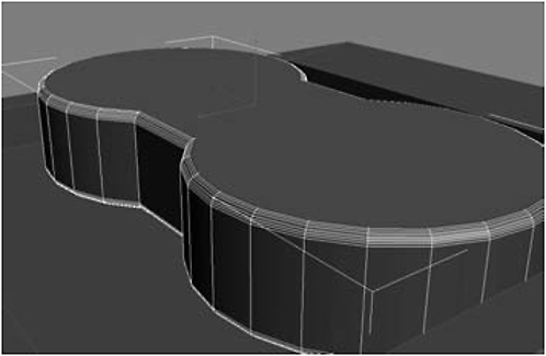
Figure I-93

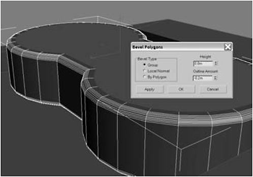
Figure I-94

Figure I-95
51. Select and delete the top polygon.

Figure I-96
52. Select the object you’ve been working on, rename it torso, and then select the bottom polygon.
53. Click the Bevel Settings button to bevel the bottom polygon and then delete it.

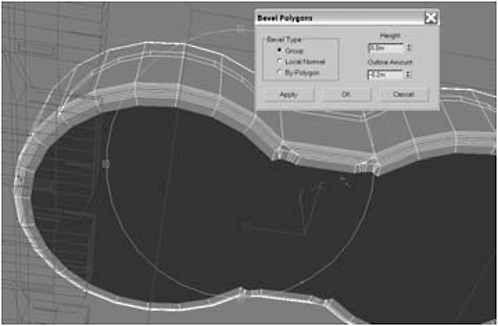
Figure I-97

Figure I-98
54. Click the Polygon selection mode button to turn it off and select the object you’ve been working on. Hit W to select the Move tool, and Shift-drag the object up, around 2 in the Z axis.

Figure I-99

Figure I-100
55. Create four clones and then select the base, click the Attach List button, select the clones, and click Attach.

Figure I-101
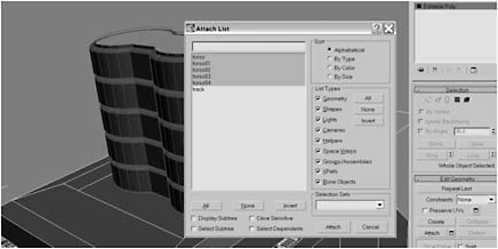
Figure I-102
56. Click the Element selection mode button and click the legs you made from clones. Right-click on the Scale tool, select Non-uniform Scale, and scale the legs 150 in the Offset World Y axis (or more if you want thicker legs).

Figure I-103

Figure I-104
57. A quick render (hitting F9) shows the legs look good but are a little rough. If you like this look, skip the next step. Otherwise, close the render window, click the Modifier drop-down list, and add a Smooth modifier to the stack to smooth the model.

Figure I-105
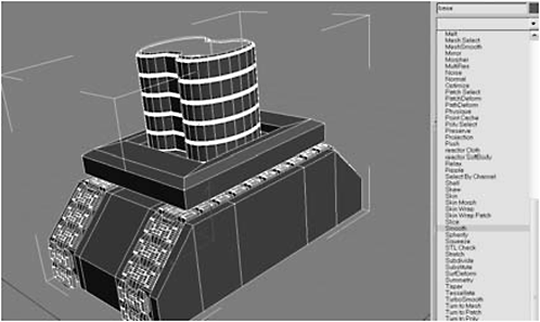
Figure I-106
FYI: It’s called “the stack” because you can stack modifiers on top of each other to achieve special effects. The order in which the modifiers appear in the stack (top to bottom) will change the effect on the model. Using the stack, like nesting materials, can give you some very sophisticated effects, but can be challenging. For that reason, we won’t be adding more than a couple modifiers to the stack at a time. Collapsing the stack makes a permanent change (which you can undo) to the model. Until that point, you can add, remove, and move modifiers within the stack.
58. Click the Auto Smooth check box, right-click the Smooth modifier, and select Collapse To to collapse the stack.

Figure I-107

Figure I-108

Figure I-109
Day 2: Finishing the Bot
1. Switch to the Top viewport. In the Create panel’s drop-down list, select Extended Primitives, then click the Capsule button. Use these values for the Capsule:

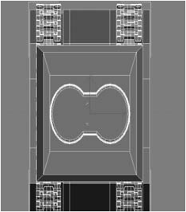
Figure I-110
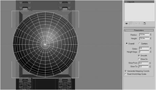
Figure I-111
2. Right-click the capsule and choose Convert to Editable Poly. Right-click the Scale tool, switch to Non-uniform Scale, and type 75 for the Offset World Z axis.

Figure I-112

Figure I-113
3. Hit W to activate the Move tool and move the capsule up in the Z axis until it is just covering the top of the legs. Toggle to wireframe mode (F3), then click the Arc Subobject Rotate tool and rotate until you can see the bottom of the capsule. Then select a polygon at the center of the tip and click Grow until six rings of polygons have been selected.
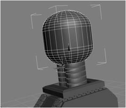
Figure I-114
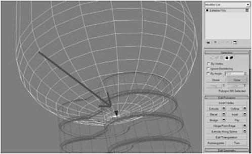
Figure I-115
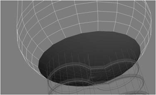
Figure I-116
Figure I-117

Figure I-118
5. Click Bevel Settings, bevel the cap, click the Polygon selection mode button to turn it off, select the base, click Attach List, and attach the capsule to the base.

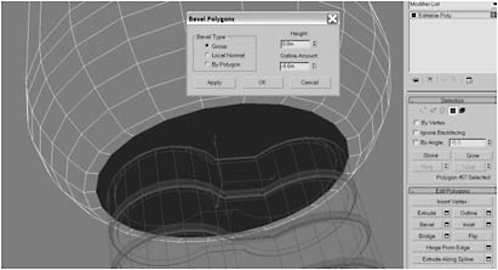
Figure I-119
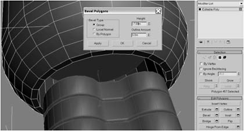
Figure I-120
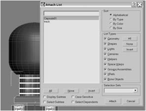
Figure I-121
6. [Optional Step] Since this is a static model and I don’t intend to animate it, I’m going to attach the track. So… select the base, click Attach List, select track, and click Attach. However, if you wish to animate this track, you’ll have to link it to the base so it will move along with the base as well as on its own. If desired, select the track and on the main toolbar click the Select and Link tool (third button from the left). Click the base to make it the track’s parent. Then hit the Q key to turn off the tool and reactivate the main selection tool.
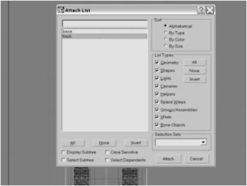
Figure I-122
7. Click the Polygon selection mode button, then hold down the Ctrl key and select the polygons you see in Figure I-123. Click Bevel Settings:


Figure I-123
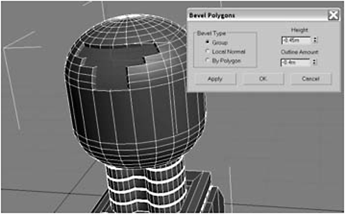
Figure I-124
8. [Optional Step] If you prefer an illuminated bezel to a radiator, skip step 9, click Detach, detach as object, and name the object bezel. Select and Link the bezel to the body. Now you can add a translucent material to the bezel and place a light beneath it to achieve a really cool effect.
9. With the same polygons selected, under the Edit Geometry rollout click the Tessellate Settings button and click Apply twice, then click OK. Click Bevel Settings:
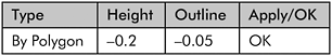

Figure I-125
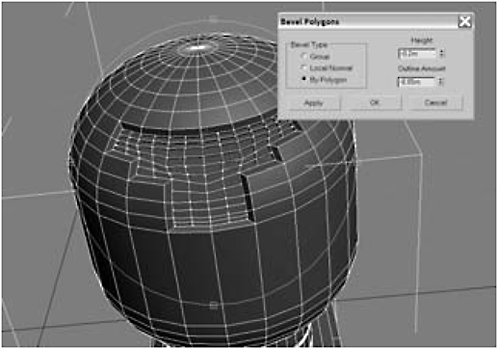
Figure I-126
Fire Drill: For the “obsessives” in the audience, I’m aware that the tessellated polygons are not straight or evenly sized. This is intentional. Ever take a close look at a car radiator? With age, the little aluminum blades get nicked and dented, and sometimes badly caved in. That’s the effect I was going for. If this bugs you (and I know it will bug some of you), feel free to select the individual vertices and move them using the Move tool to straighten the grating and right this outrageous wrong. I won’t think any less of you. In the meantime, the rest of us are going to pop a Corona and put on a Jimmy Buffett CD while we wait.


Figure I-127

Figure I-128
11. Bevel the two front polygons twice more:

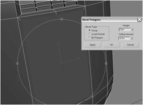
Figure I-129

Figure I-130
12. Edge-select the inner three edges, click the Connect button, enter 2 in the Segments field, and click OK.
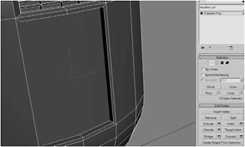
Figure I-131
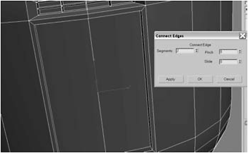
Figure I-132
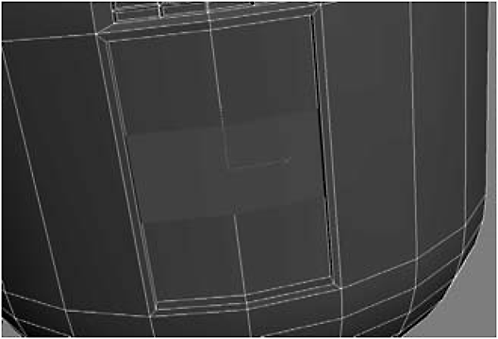
Figure I-133

Figure I-134
14. Tessellate twice and then click the Bevel Settings button. Use the values in the following tables:

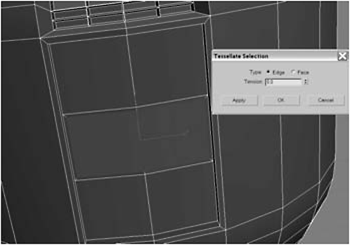
Figure I-135

Figure I-136


Figure 1-137
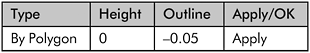

Figure I-138
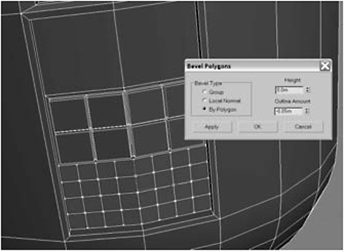
Figure I-139

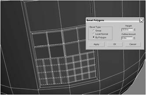
Figure I-140
FYI: MSmooth can be used to make a round object from a rectangular one. First, make the object as square as possible. Then make a small inward extrusion (usually 0.01).
16. Click MSmooth and then click the Grow button.

Figure I-141

Figure I-142

Figure I-143
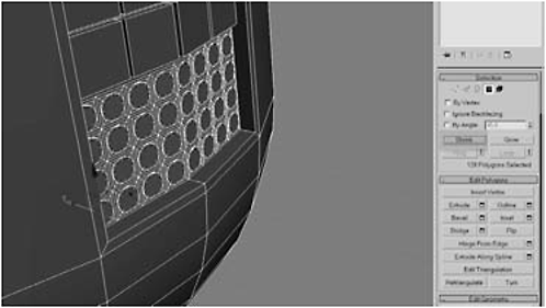
Figure I-144
18. Bevel the polygons. Then select 10 polygons on the bottom edge of the body, as shown in Figure I-146.

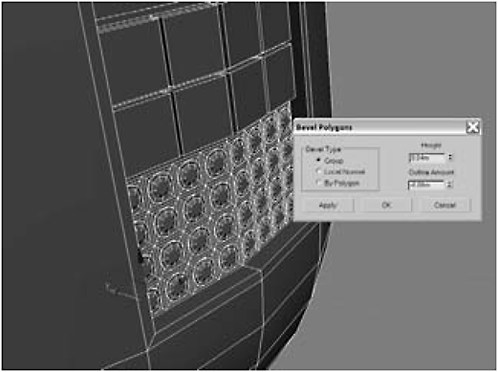
Figure I-145

Figure I-146


Figure I-147

Figure I-148
20. Select the polygons on the second, fourth, sixth, eighth, and tenth rows. Bevel the polygons:


Figure I-149
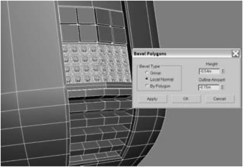
Figure I-150
21. Using AutoGrid, create a Sphere for the left eye. Convert the sphere to an Editable Polygon, Arc Subobject Rotate around the back, and delete the backward-facing polygons.

Figure I-151

Figure I-152
FYI: To make a hemisphere, create a sphere and then set Hemisphere to 0.50.
22. Using the Move tool, Shift-drag to clone the right eye. Select the body, click the Attach List button, hold down the Ctrl key, and click the two spheres. Then click Attach.

Figure I-153
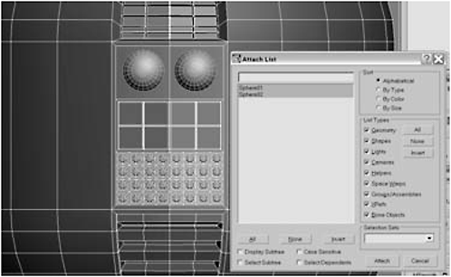
Figure I-154
23. Switch to the Top viewport (T), use AutoGrid to create a Torus (a doughnut) on top of the body, and then choose Convert to Editable Poly.
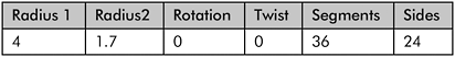

Figure I-155
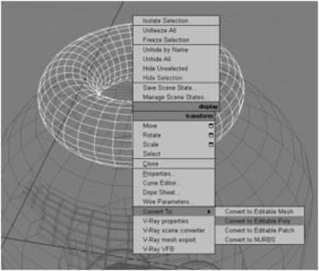
Figure I-156
24. Toggle to wireframe (F3), select a vertical edge, and then, under the Selection rollout, click the Ring button.
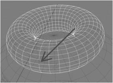
Figure I-157
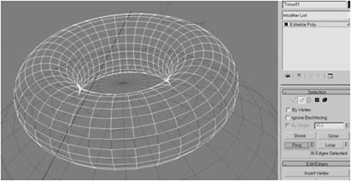
Figure I-158
25. Under the Selection rollout, click the Loop button, and then Extrude the edges to an Extrusion Height of 0.8 with an Extrusion Base Width of 0.5.
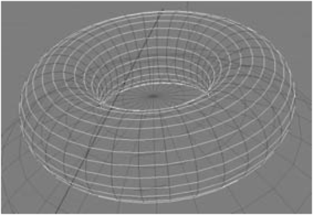
Figure I-159

Figure I-160
26. Uniform Scale the torus by typing 85 in the Offset World field. Switch to the Front view (F), right-click on the Scale tool, select Non-uniform Scale, and type 60 for the Offset Screen Y axis.
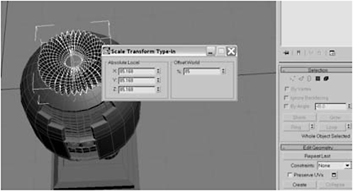
Figure I-161
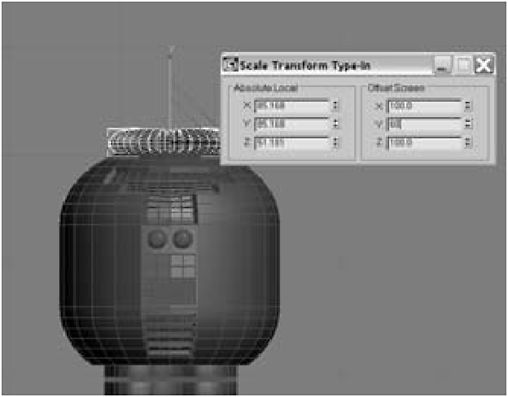
Figure I-162
27. Select the body, click the Attach List button and choose Torus01. Switch to the Top view and select the 24 polygons on the top of the body that are visible through the torus’ hole.
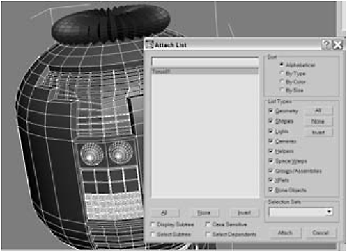
Figure I-163
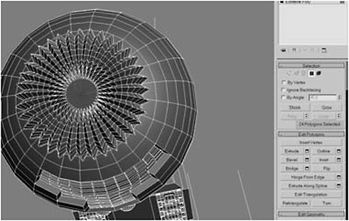
Figure I-164
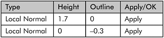
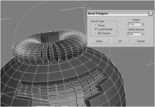
Figure I-165

Figure I-166


Figure I-167
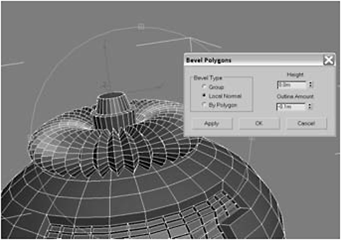
Figure I-168
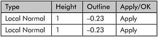

Figure I-169
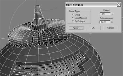
Figure I-170


Figure I-171
29. Switch to the Top view. On the Create panel, use the drop-down list to select Extended Primitives, click Chamfer Cylinder, and use AutoGrid to create a Chamfer Cylinder on top of the body. Enter these values for the object:


Figure I-172
30. Convert the chamfer cylinder to an Editable Polygon, then select the top 64 polygons (up to the start of the fillet) and use the Move tool to raise them around 0.1 in the Z axis.
Figure I-173
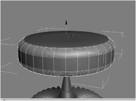
Figure I-174
31. Click the Shrink button to shrink the selection, and raise the remaining polygons around 0.6 in the Z axis. Open the Modifier list and add a MeshSmooth modifier to the stack.
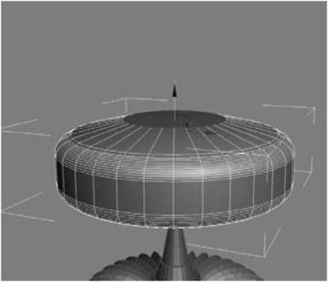
Figure I-175
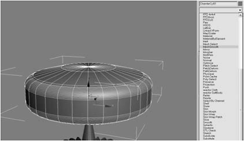
Figure I-176
32. Under Subdivision Method, make sure NURMS is shown in the drop-down list, and that Apply To Whole Mesh is selected. Then enter 2 in the Iterations field, 1 in the Smoothness field, and make sure Render Values Smoothness is checked and set to 1.

Figure I-177
33. Right-click on the MeshSmooth modifier and choose Collapse All to make the modifier permanent. Switch to the Front view (F)and use the Move tool (W) to lower the cap in the Y axis until the antenna enters the cap about halfway.

Figure I-178
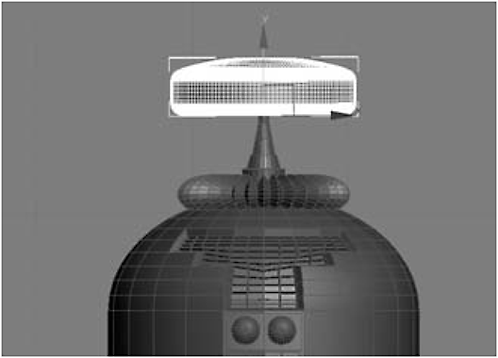
Figure I-179
34. Select the body, click the Attach List button, and choose ChamferCyl01 to attach the chamfer cylinder.

Figure I-180
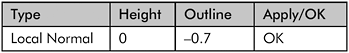

Figure I-181

Figure I-182
36. Select the new faces made by the bevel on the right side. Click Hinge From Edge, enter –30 for the Angle and 10 for the Segments, click the Pick Hinge button, and click the leftmost edge.
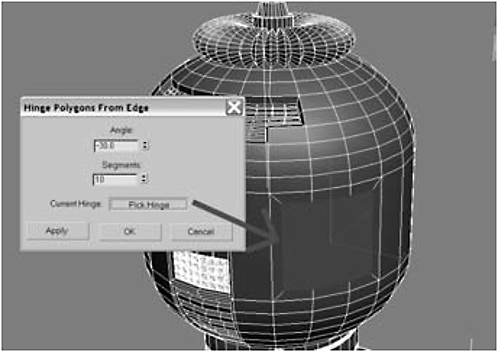
Figure I-183

Figure I-184
37. Repeat the Hinge From Edge procedure for the other side:

Figure I-185
38. Using AutoGrid, create a Cylinder inside the armhole on the right side, and then apply a Bend modifier to its stack.
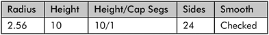
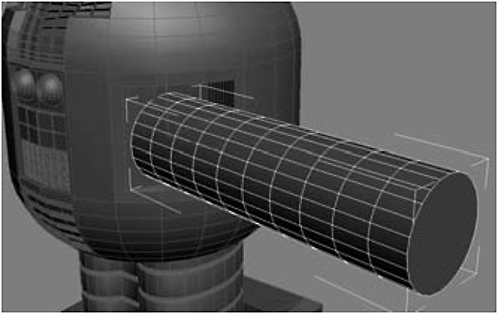
Figure I-186

Figure I-187
39. Set the Bend Angle to –100 and the Bend Axis to Z.
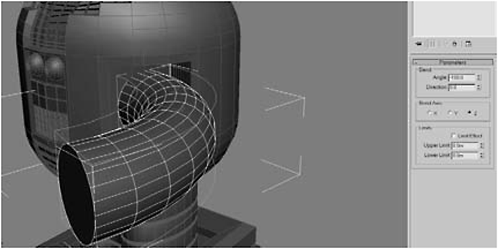
Figure I-188
40. Right-click the stack and choose Collapse All. Polygon-select the front of the arm.

Figure I-189
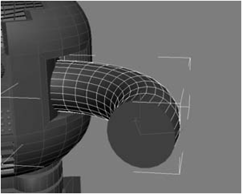
Figure I-190


Figure I-191

Figure I-192


Figure I-193
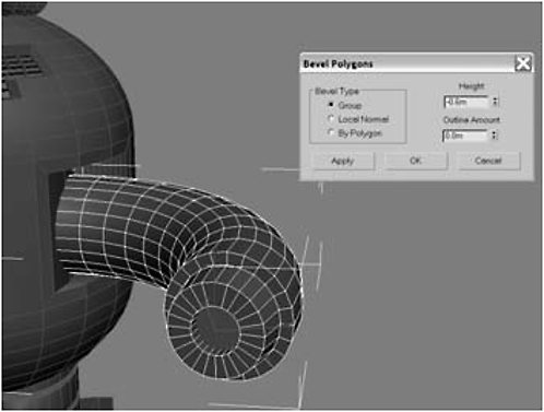
Figure I-194
42. Now let’s create a claw. Switch to the Right viewport and, using AutoGrid, create a Tube with these settings:

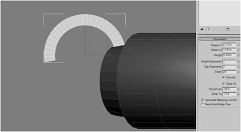
Figure I-195
43. Switch to the Top viewport and rotate –27 on the Z axis (the inner yellow circle control rotates an object in Z).
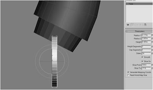
Figure I-196
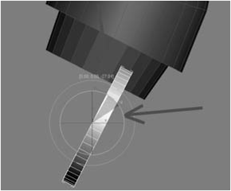
Figure I-197
44. Switch to the Move tool. There is a yellow square between the X and Y axes. Dragging on the square allows you to move in both axes simultaneously. Move the claw in the X/Y to center it on the front of the arm.

Figure I-198
45. Increase the Height of the claw to around 0.96, and then switch to the Move tool. Notice the Move gizmo’s axes are pointing in directions that are not very useful.

Figure I-199
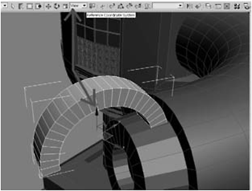
Figure I-200
46. Change the Reference Coordinate System from View to Local and notice that the gizmo realigns itself to be oriented to the claw. Move the claw in the X axis to center it on the front of the arm.

Figure I-201

Figure I-202

Figure I-203

Figure I-204
48. Select the Hierarchy tab, click the Pivot button, and under the Adjust Pivot rollout, click Affect Pivot Only. Note the position of the Pivot gizmo.

Figure I-205
FYI: An object’s pivot starts out centered. In the case of a tube, it starts out in the center of the tube. You can create a clone by holding down the Shift key and using the Rotation tool. Objects rotate around their pivots, so when you make clones using the Rotation tools, the clones are made around the pivot of the original.
Affect Pivot Only moves the pivot point while leaving the original object in the same position.
49. Move the pivot down in the X axis and center it in front of the hole in the front of the arm.

Figure I-206
50. Click the Create panel icon to turn off Affect Pivot Only. Click the Angle Snap Toggle button on the main toolbar (this limits rotation to 5 degree increments). Change the Reference Coordinate System to Local, then click the Rotation tool on the main toolbar.

Figure I-207
51. Hold down the Shift key and rotate the middle, yellow ring until the X axis reads 90 degrees. Switch the Object type to Instance, set the Number of Copies to 3, and set the Name to claw.

Figure I-208

Figure I-209
52. Select the arm, click the Attach List button, hold down the Ctrl key, click the claws, and click the Attach button. Click Affect Pivot Only, then move the pivot to the center of the body.
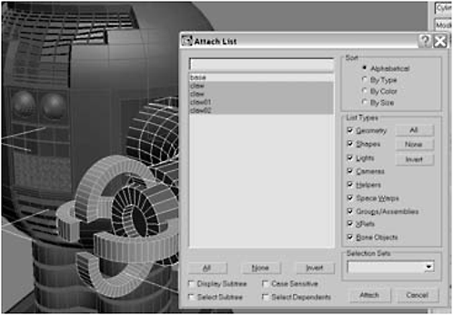
Figure I-210
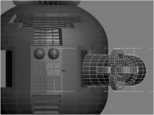
Figure I-211
53. Switch to the Front view. Click the Mirror button on the main toolbar, select XY as the Mirror Axis and Instance under Clone Selection, and then click OK.
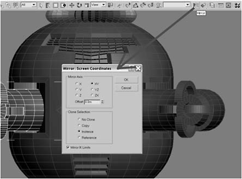
Figure I-212
54. Select the body, click Attach List, hold down the Ctrl key, select Cylinder01 and Cylinder02 (the arms), and click Attach.

Figure I-213

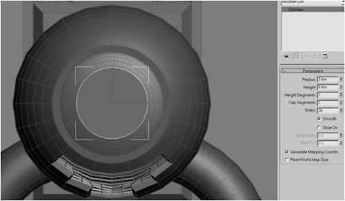
Figure I-214
56. Switch to the Front view and move the cylinder down until it rests atop the antenna. Select the body and attach the cylinder.

Figure I-215

Figure I-216
Fire Drill: Okay … so why does the image at the beginning of the chapter look photorealistic and your finished model looks … well … like this. For the uninitiated, a 3D model is always going to look like this. Sorry to burst your bubble. What makes your model look real is the textures you apply and the renderer you use. Texturing and rendering are so complex in their own right that entire books are dedicated to just these topics. To get you off to a good start with lighting, check out Nicholas Boughen’s excellent book, 3ds Max Lighting (Wordware, 1-55622-401-X). To learn more about rendering using Max’s excellent built-in mental ray rendering engine, check out Joep van der Steen’s excellent Rendering with mental ray & 3ds Max (Focal Press, 978-0240808932).
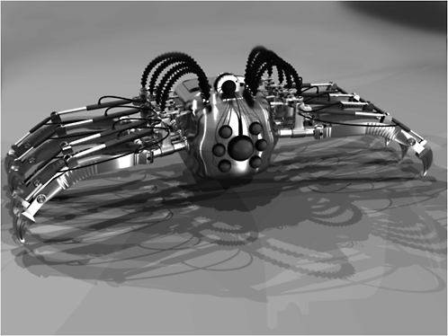
Here’s the spider bot we create in Chapter 1.