
Chapter 1
Spider Bot
In this chapter, you’ll learn to make a small surveillance bot like the one in the video game Deus Ex: The Invisible War. Let’s face it: A spider bot isn’t as sexy as, say, a heavily armored mech. But though they look complicated, spider bots are generally easy and quick to build.
Day 1: Building the Body
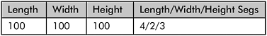

Figure 1-1
2. Right-click the box and select Convert To > Convert to Editable Poly.

Figure 1-2
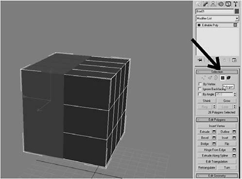
Figure 1-3
4. Delete the selected polygons. Click the down arrow next to the Modifier List, select the Symmetry modifier to add it to the stack, and under Mirror Axis select X and check Flip.

Figure 1-4
 FYI: A Symmetry modifier mirrors any changes you make to the original object. This modifier is especially handy when building objects with two identical sides, like a human head, because you only have to make changes to one side.
You can toggle modifiers on and off in the viewports. There’s an icon at the bottom of the stack that looks like a test tube. When it’s pressed, the effects of the modifier will be shown in the viewport. When it’s unselected, the modifier ’s effect will be turned off.
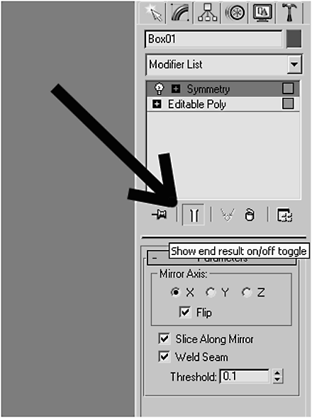
Figure 1-5
5. Click the plus sign next to Editable Poly in the stack and it will give you a list of selection options. Click Polygon.
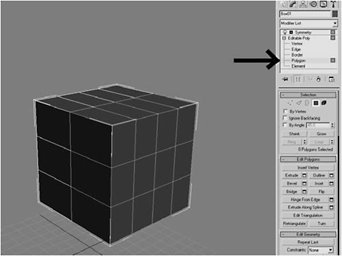
Figure 1-6
6. Select one of the polygons and use the Move tool (W) to pull the polygon in the X axis. Notice how the other side automatically follows:
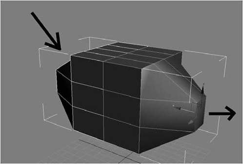
Figure 1-7
FYI: The most popular methods of 3D modeling are polygonal (sub-D) and NURBs. Polygonal modeling, which is what we’ll do in this chapter, is the easier of the two and lends itself to making hard-edged, inorganic models, like robots. The downside is that it’s hard to make smooth surfaces with just polygonal modeling. NURBs are great for making smooth surfaces, but they ’re a bit harder to work with and are harder to use to make hard-edged surfaces.
In order to have the modeling ease of polygons but achieve a smooth, injection-molded look, we’ll use a MeshSmooth modifier. When added to the stack, a MeshSmooth modifier takes the underlying polygon model and adds additional geometry to smooth it out.
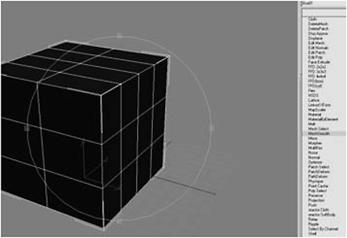
Figure 1-8
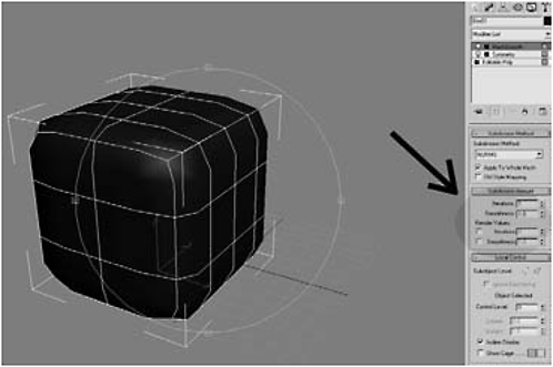
Figure 1-9
FYI: In most modeling situations, you only need to worry about the controls under the Subdivision Amount rollout. The more iterations you add, the smoother your model will be, but… each iteration adds more geometry, which means a bigger hit on your system resources. In most instances, you don’t need more than around three iterations. Also, you want to set your render iterations higher than your viewport iterations. That way, you can “rough out” your model with a minimal resource hit and use the higher iterations for final rendering.
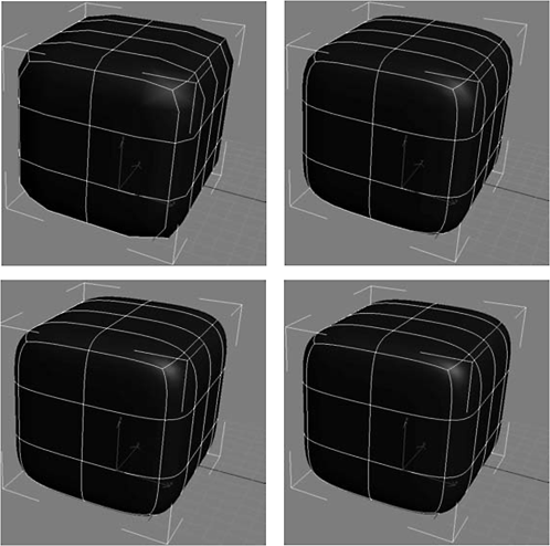
Figures 1-10 to 1-13 One iteration through four iterations
As you can see, after three iterations you reach a point of diminishing returns. The surface continues to get smoother, but the changes are so small they ’re hard to detect. Generally, you want to model at iteration 1 or 2 and use a setting of 3 or 4 for your rendering. You can best understand how this smoothing process works by switching to wireframe and unchecking Isoline Display under Local Control.
Notice what’s happening. Each iteration subdivides the object into smaller and smaller polygons. This is why it’s called subdivision surfacing or sub-D.

Figures 1-14 to 1-17 One iteration through four iterations
9. Set Iterations to 2, select the same polygon you did in step 6, and pull out it out the same way.
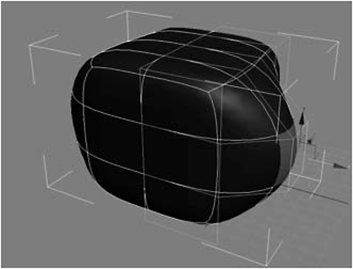
Figure 1-18

Figure 1-19
FYI: Note the differences between step 6 and step 9. If you click the light bulb icon to the left of the MeshSmooth modifier, it will toggle the modifier on and off. If you toggle it off, you’ll see that nothing has changed from a modeling point of view; the modifier simply refines the underlying model.
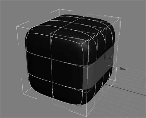
Figure 1-20
11. Under the Edit Polygons rollout, click the Extrude Settings button.
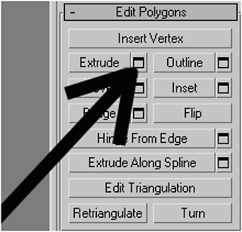
Figure 1-21
FYI: Throughout Max, you’re given a choice, as you are here, of clicking a button and using a gizmo to perform actions (e.g., extrusions) by hand and eye, or clicking to open a settings box and typing exact values. One of the things I dislike about a lot of video tutorials is they do a lot of modeling using the gizmo technique, which makes it hard to achieve the same results. This can be very frustrating when you’re just learning. Perhaps it’s because I’m an engineer and not an artist that I prefer to enter exact values.
12. When the settings box opens, select By Polygon as the Extrusion Type and set the Extrusion Height to 0.1. Click Apply.*
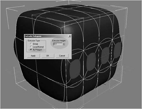
Figure 1-22
* Thanks to Matt J. Bell for teaching me the sub-D process. His four-legged spider bot, which appeared in Issue 40 of 3D World, was the first 3D model I ever made, and his tutorial was the first training I had in 3D modeling.
13. Perform another extrusion by changing the Extrusion Height to 2.0 and clicking Apply.

Figure 1-23
14. Extrude again with the Extrusion Height set to 1.0 and click OK (not Apply) to complete the extrusion and close the dialog box.

Figure 1-24
FYI: What’s with the small extrusions? When you are using NURMS or MeshSmooth, the closer together the edges, the sharper the edges of the end product. Consider the three identical boxes in the top row in Figure 1-25. The only difference between them is the number of edges and how close those edges are. Compare their NURMS versions in the row below, and see how close edges serve to straighten the edges. This process of placing edges close together to make sharper corners when using NURMS is called “increasing the tension,” because adding edges close together is somewhat like stretching the skin of a drum.
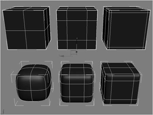
Figure 1-25
15. Right-click on the Select and Uniform Scale button on the toolbar to open the dialog box, type 70 in the Offset World field, and click the close (X) button.
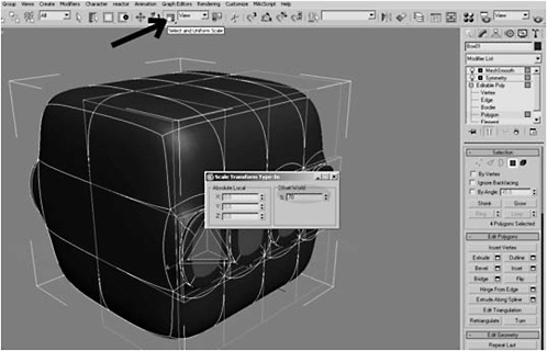
Figure 1-26
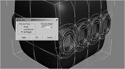
Figure 1-27
17. Select the front three polygons and Move (W) them –20 units in the Offset World Y axis.
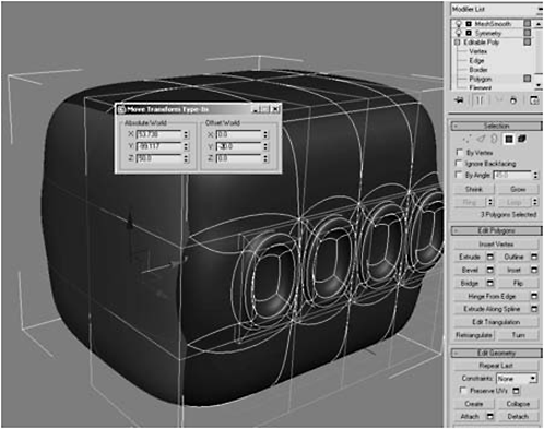
Figure 1-28
18. Select the Symmetry modifier, then right-click and select Collapse To to make the Symmetry modifier permanent.
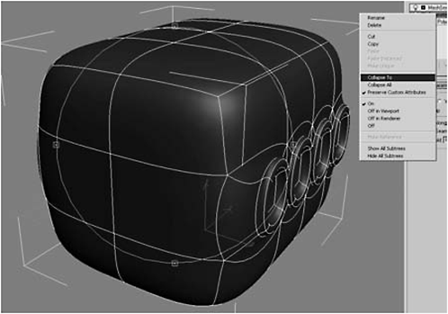
Figure 1-29
FYI: Converting to an Editable Polygon collapses all the modifiers and makes them permanent. On the other hand, Collapse To collapses only the selected modifier down one level. For now we want to keep MeshSmooth, but we’re done with the Symmetry modifier.
19. Select the front four polygons, right-click the Scale tool, and type 80 in the Offset World field to scale the polygons down by 80 percent in all axes.

Figure 1-30
20. Switch to the Front view and, using AutoGrid, create a Tube and center it in the middle of the front surface of the bot using these settings:
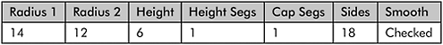

Figure 1-31
21. Right-click and choose Convert to Editable Poly, switch to wireframe (F3) to get a better view, Arc Rotate so you can see the back of the tube, and delete the back-facing polygons. (Back-facing polygons are those that face toward geometry that no one will see.)

Figure 1-32
 Don’t Forget: It’s good practice to delete polygons that no one is ever going to see. The more polygons you have, the longer it takes to render. While we won’t specifically focus on building low-polygon models in this book, the ability to build low-polygon models is a skill valued by the game industry.
22. Next, delete the polygons inside the tube, since this will be a socket for an eye and nobody will see these polys either.

Figure 1-33
23. Under Subdivision Surface, click Use NURMS Subdivision. Set the Display Iterations to 2 and the Render Iterations to 3.

Figure 1-34
FYI: So why didn’t I use a MeshSmooth modifier here? Generally, I use a MeshSmooth modifier either when I want the option of making the smoothing permanent by collapsing the stack or when I want it to interact with one or more other modifiers. Use NURMS Subdivision does the same thing, but you can toggle it on and off.
24. Switch to Border selection mode and select the border of the tube that touches the bot’s body; again, this is easier to do in wireframe (F3).

Figure 1-35
25. Switch back to shaded mode (F3), click Create Shape From Selection, and name the shape seal.
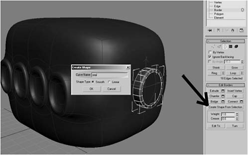
Figure 1-36
FYI: This technique is really slick for creating great-looking “seals” on mechanical models. Create Shape From Selection takes the selection and creates a spline object; in this case, a ring. You then select the shape and, under its settings, make it renderable. After you’re satisified with the size and shape, you convert it to an Editable Polygon.

Figure 1-37
27. Under Rendering, check Enable In Renderer and Enable In Viewport.

Figure 1-38

Figure 1-39
29. Select the tube. Under Edit Geometry, click Attach List, select seal from the list, and click Attach to attach the seal to the tube.

Figure 1-40
30. Rename the tube to eye_socket, click the Select and Link button on the toolbar, and drag the eye_socket onto the body.

Figure 1-41
FYI: So why use Select and Link? Why not use Attach? Attach does more than “attach” one object to another; it makes the selected object a part of the other object. Using Select and Link, the objects maintain their own identity but are linked, in a parent-child relationship, for the purpose of animation. Specifically, when the parent is moved, the child object follows. How do you know which is which? When you use Select and Link, the selected object is the child and the object you drag it onto is the parent. In our case, the body is the parent and the eye_socket is the child. So whenever we move the body, the eye_socket will follow as if it were glued to the body. However, Select and Link does not affect your ability to animate the child separately from the parent.
31. Switch to AutoGrid and create a Sphere with a Radius of 12.55 in the center of the tube.

Figure 1-42
32. Convert the sphere to an Editable Polygon, select a segment of the third ring, and click the Loop button to select the entire ring.

Figure 1-43
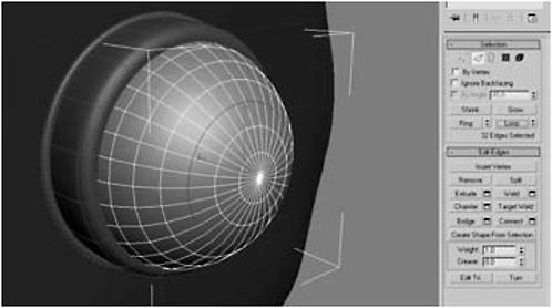
Figure 1-44
33. Click the Extrude Settings button and enter an Extrusion Height of –0.8 and an Extrusion Base Width of 0.04.
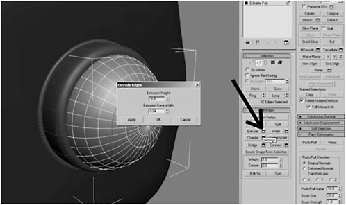
Figure 1-45
FYI: This extrusion pulls the selected edges inward, creating a groove that visually separates the iris from the rest of the eye.
34. Rename the sphere to eye and the boxto body.
35. Select and Link the eye to the eye_socket, and click the Schematic View button on the main toolbar.
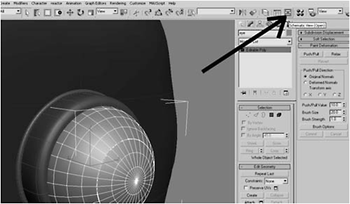
Figure 1-46
FYI: Schematic view is handy because it graphically shows all the linkages between objects. Admittedly, it’s not particularly useful yet, but it does show that the eye is parented to the eye_socket and the eye_socket is parented to the body. Schematic view becomes more powerful when your scene contains multiple objects with large numbers of interlinked pieces (see Chapter 2, “Hunter-Killer”).

Figure 1-47
36. Select the eye and the eye_socket. Select Group from the Group menu, type eye_assembly in the name field, and then click OK.

Figure 1-48
 Fire Drill: Contrary to what you may think, grouping objects does not link them together for the purposes of animation, nor does it attach them together. So why do it? Using Group allows us to easily select a collection of elements we want to perform an operation on; in this instance, cloning.
37. Select the eye_assembly, select the Move tool (W), hold down the Shift key, and click and drag in the X axis to create a clone.

Figure 1-49

Figure 1-50
38. Right-click on the Scale tool and type 50 in the Offset World field.

Figure 1-51
39. Move the smaller eye in the X axis until its position is as shown in Figure 1-52.
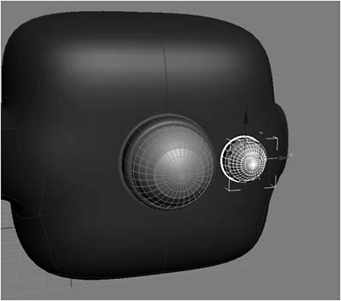
Figure 1-52
40. Shift-move the smaller eye in the Z axis and create two clones.
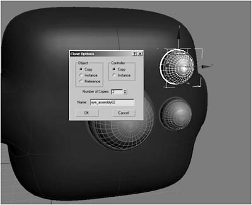
Figure 1-53
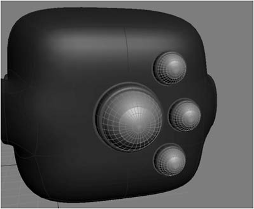
Figure 1-54
42. Select the three smaller eyes, click Mirror, mirror them in the X axis, and use an Offset of –38.454 to position them.

Figure 1-55
43. Select and Link the six smaller eyes to the body.
44. Arc Rotate in the Perspective view until you are happy with the angle you’re viewing the bot from, and hit F9 to do a quick render.

Figure 1-56
 Message: Don’t worry if the default colors make your render look “cartoonish.” Take a look at the three materials videos on the companion DVD to see how the use of materials can make the bot look more menacing.
Figure 1-57
 Urgent: If you look at Figure 1-57, you’ll see that the smaller eyes are protruding too far. We need to select them and move them back into the body, so that the seals are flush with the body. Since the body is irregularly shaped, you will also need to rotate some of the eyes slightly so they are snugly placed against the body.

Figure 1-58
FYI: When building a model with a large number of parts, it’s sometimes easier to separate parts (e.g., the eyes) into separate layers, which you can turn on or off or freeze to prevent you from accidentally selecting them. So why would you want to turn “off” a layer? Sometimes, when you have a lot of parts, some parts can get in the way of your viewing or modeling. Also, when you have a high number of polygons, your system can start to drag. Turning off a layer with a high number of polygons, such as the eyes in this model, will free your computer from having to compute all those polys while you’re modeling a different part.
45. Click the Layer Manager button on the main toolbar to open the Layer Manager.

Figure 1-59

Figure 1-60
46. Hit the H key and select the eye_assembly objects.

Figure 1-61

Figure 1-62
48. A new layer (Layer01) appears. Click the + to the left of Layer01 to show that all the selected objects have been added to that layer.
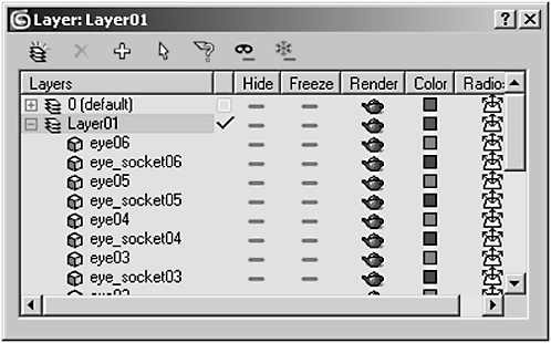
Figure 1-63
FYI: Long-time Adobe users will be intimately familiar with the concept of layering. If you are not in that group, suffice it to say that nothing much has really changed other than your objects have been separated into layers that can be turned on and off for convenience. In this case, the eyes have been put on a layer separate from the body.
49. Click Layer01, rename it eyes, and click on the dash in the Hide column. A little burglar mask icon appears, indicating that the layer has been hidden. To show it again, all you have to do is click the burglar mask to toggle the layer.

Figure 1-64
50. Make sure a check mark is shown next to the default layer (which is the layer the body is on) and not the eyes layer. If not, click in the box beside the default layer as shown in Figure 1-65.

Figure 1-65
Fire Drill: The check mark indicates the layer on which new objects will be created. If you’re trying to create objects and Max seems to be making them but they ’re not appearing, chances are you’re looking at one layer but creating on a hidden layer. For example, if we had left the check mark next to the eyes layer (which is invisible), any objects we created would’ve been invisible because they were being created on an invisible layer.
Day 2: Building the Legs
Spiders have eight legs, so that requires a lot of work to model. Rather than reinventing the wheel eight times, we’ll simply make one leg and then clone it seven times.
1. Switch to the Perspective view, click the Polygon selection mode icon in the Selection rollout, and marquee-select the left half of the model.
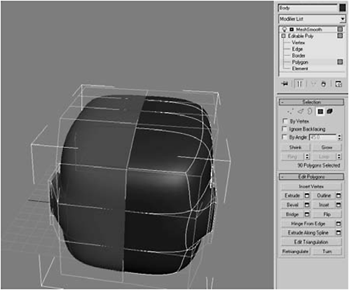
Figure 1-66
2. Delete the selected polygons, select Editable Poly in the stack, and add a Symmetry modifier between MeshSmooth and Editable Poly.

Figure 1-67
FYI: At this point, you might ask why we went to all the trouble of collapsing the stack to remove the Symmetry modifier (see step 18 on page 71) only to add it back in this step. Collapsing the first modifier was necessary for correctly scaling the bot’s nose, which we’ll see is a necessary component in an upcoming step.
3. Click the light bulb icon next to the MeshSmooth modifier to turn it off. Then, under Editable Poly, select Polygon and select the four inner polygons on the sockets on the right side.
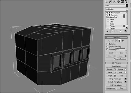
Figure 1-68
Don’t Forget: If you’re only seeing half of the model, when you click Polygon under Editable Poly, click the little test tube icon at the bottom of the stack to show the effects of the modifiers. The MeshSmooth effect will not show, however, because you temporarily turned it off with the light bulb icon.
4. Switch to the Front view, switch to wireframe mode, switch to the Move tool, and move the polygons –8.196 on the X axis or until the first edge coincides with the front edge of the nose.

Figure 1-69

Figure 1-70
5. Toggle MeshSmooth back on, switch to the Front viewport, and create a Sphere with a radius of 8.5 in the socket, using AutoGrid.
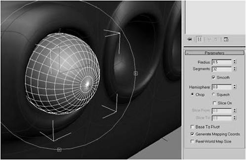
Figure 1-71
6. Convert the sphere to an Editable Polygon, select and delete the top three rows of polygons, and Cap the hole.
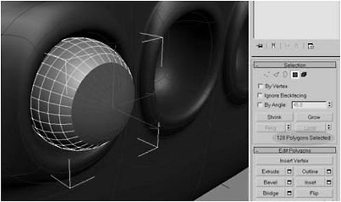
Figure 1-72

Figure 1-73

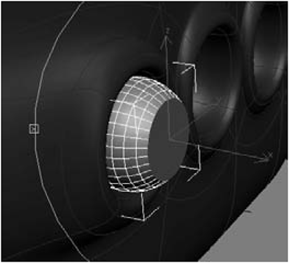
Figure 1-74
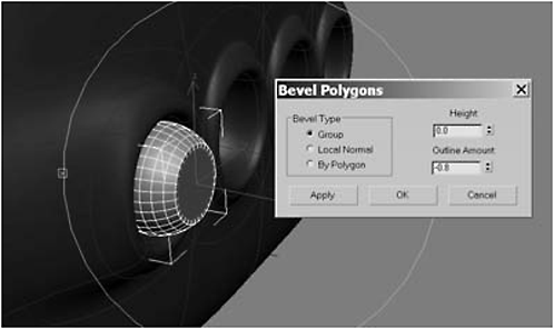
Figure 1-75
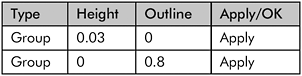
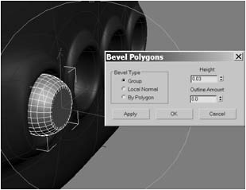
Figure 1-76
Figure 1-77

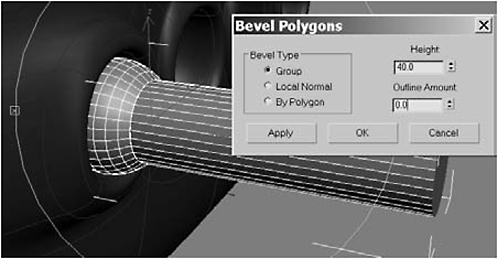
Figure 1-78
8. In the Right view, create a Sphere with a Radius of 8.5, using AutoGrid, over the shaft you just made:

Figure 1-79
9. Delete the 128 polygons shown in Figure 1-80 from the sphere, delete the end polygon on the shaft, move the sphere against the shaft, and align the edges of the shaft with the edges on the sphere as shown in Figure 1-81.

Figure 1-80
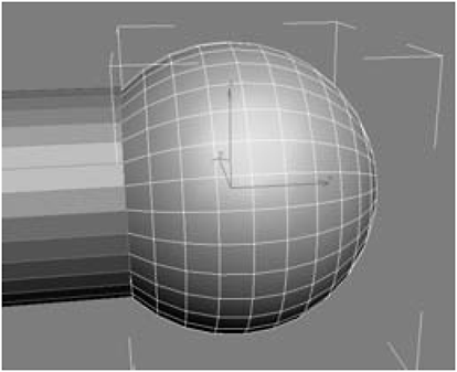
Figure 1-81
10. Select the shaft, click Attach, attach the sphere, switch to Vertex selection mode, select the vertices where the shaft and the sphere meet, and then click Weld (adjusting the Weld Threshold until the number of After polygons is 32 less than the Before).

Figure 1-82
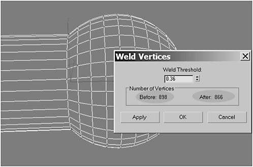
Figure 1-83
11. Using AutoGrid, create a Tube on top of the ball joint you just made. Then switch to the Front view, and center the tube on the ball joint. Use these settings for the Tube:
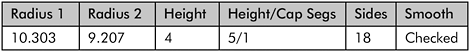

Figure 1-84

Figure 1-85
12. Change Radius 2 to 8.667, Height Segments to 1, Sides to 32,and Height to 12, then use the Move tool to center the tube vertically on the ball joint.

Figure 1-86

Figure 1-87
13. Arc Rotate around the tube to make sure it is evenly positioned on the ball joint and then click the Slice On check box. Set the Slice From to –100 and the Slice To to 13.0 to create a crescent.
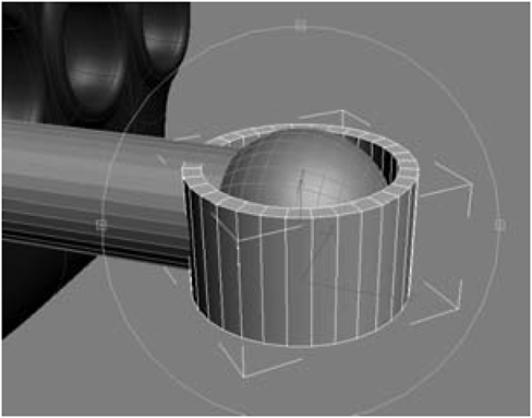
Figure 1-88
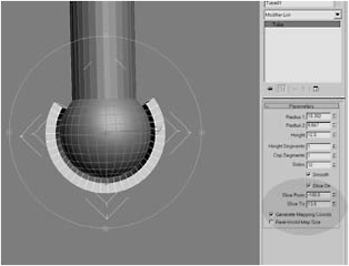
Figure 1-89
14. Switch to the Right viewport, choose Convert to Editable Poly, and select the 10 polygons on the outer surface. Then Extrude by 5 as a group.
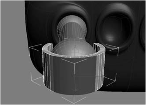
Figure 1-90
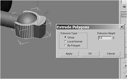
Figure 1-91
15. Switch to the Front view and use the Non-uniform Scale tool to scale the polygons down to 0 in the Offset Screen X axis. Then click Bevel Settings and enter the values in the following table.

Figure 1-92

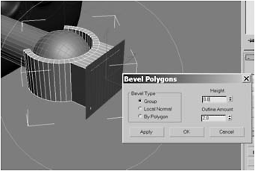
Figure 1-93
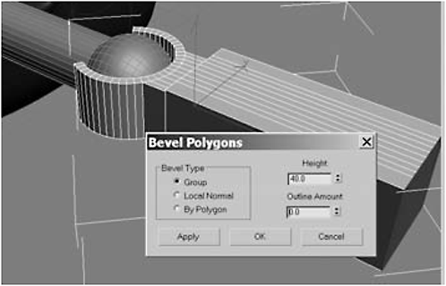
Figure 1-94
16. Extrude the end polygons by 4.0 and hit Apply nine times, then click OK.

Figure 1-95
17. Switch to the Top view and click Grow 11 times until the extrusion extends back to the joint. Then right-click the Non-uniform Scale tool and scale the polygons down to 60 in the Y axis.
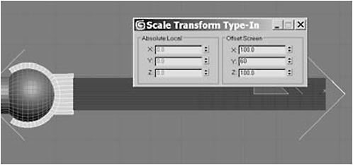
Figure 1-96
18. Click Shrink once to shrink the selection to only include the extruded tip and then add a Bend modifier to the stack.
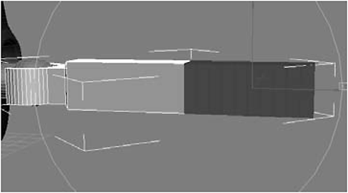
Figure 1-97
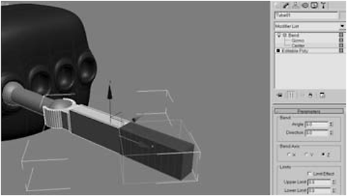
Figure 1-98
Urgent: Notice that the Bend gizmo (orange box) is turned the wrong way. Specifically, it’s turned on its side. Why? Look at the bounding box (if you have Show Bounding Box turned on) for the whole object. It’s turned 90 degrees too. What is going on? We used a Tube primitive to create the leg, and, if you recall, we created it so it was oriented vertically (i.e., rotated 90 degrees). That wouldn’t normally be a problem, but in this case, it screws up the orientation of our Bend modifier. Fortunately, like most problems we encounter, this one is easy to fix. You just need to change the orientation of the gizmo. Oh. Is that all?
19. Click the + to the left of the Bend modifier, select the gizmo, right-click on the Rotate tool, and input –45 for the Offset World Z axis.

Figure 1-99

Figure 1-100
21. With the Bend gizmo still selected, right-click on the Non-uniform Scale tool, input 110 for the Offset World X axis to stretch the gizmo to enclose the extruded tip, and close the dialog box.
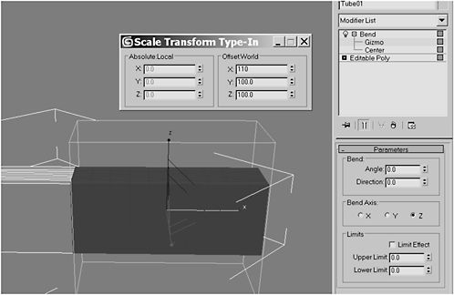
Figure 1-101
22. Select Bend Center from the stack and use the Move tool to move the center in the X axis until it’s flush with the left edge of the Bend gizmo.

Figure 1-102
23. Set the Bend Angle to 30 and the Bend Axis to Y, check Limit Effect, and set the Lower Limit to –30. Collapse the stack.

Figure 1-103
24. Select the polygon at the end of the extrusion and Extrude it by 20.

Figure 1-104

Figure 1-105
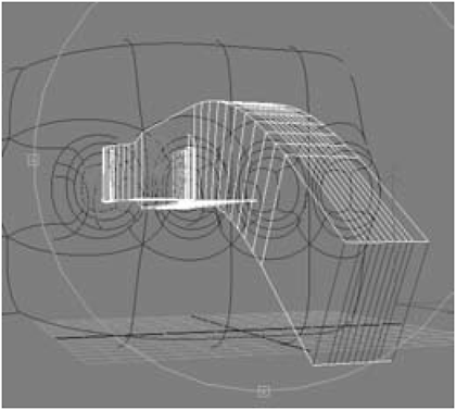
Figure 1-106
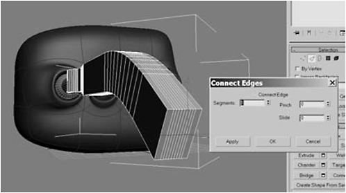
Figure 1-107
26. Select the bottom polygons and delete them.
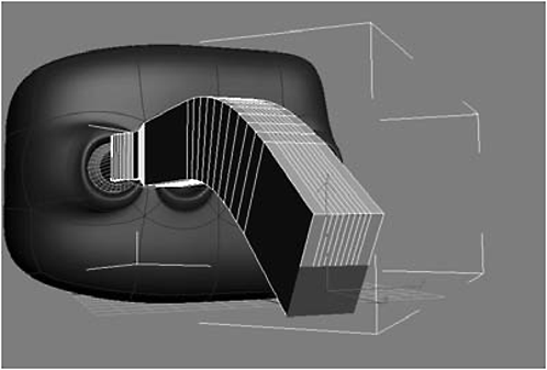
Figure 1-108
27. Select the top polygons and click Hinge From Edge. Set the Angle to 180 and the number of Segments to 10, click the Pick Hinge button, and click the edge at the bottom of the selected polygons.

Figure 1-109
28. Delete the backward-facing polygons, select the 22 overlapping vertices as shown, click Weld Settings, lower the Weld Threshold until the number of After vertices is 11 less (i.e., half of 22) than the Before, and then click OK to weld the overlapping vertices.

Figure 1-110
29. Select the polygons you just made with Hinge From Edge and Scale them down to 40 in the Y axis.
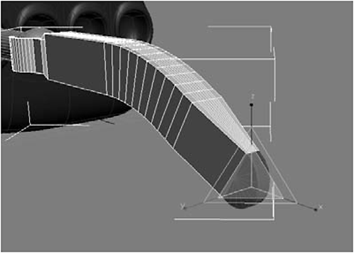
Figure 1-111
30. Switch to the Front view. Using AutoGrid, create a Cylinder in the center of the joint. Arc Rotate around the joint to make sure the cylinder is positioned equally between the two parts of the joint and intersects the ball. Use these settings for the cylinder:

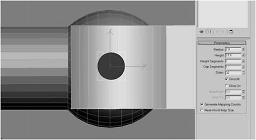
Figure 1-112
Day 3: Detailing the Body
The first thing we’re going to want to do is to create a plane beneath the body to act as a floor, and then add some seams. Bots are assembled, meaning there would be seams. Even if the body were injection molded, there’d have to be some way of taking it apart to insert the internal components.
1. Create a Plane object and position it beneath the body, then select the body, right-click the stack, and select Collapse All to collapse the stack.
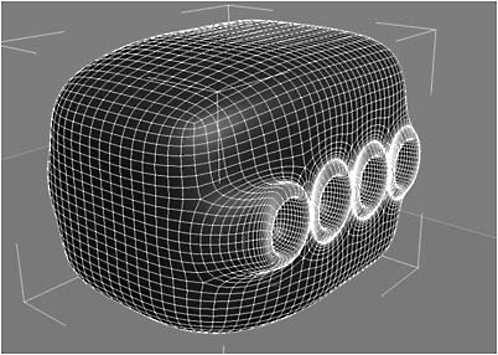
Figure 1-113
2. In the Front view, select a horizontal edge in the center of the model (just look at the model and follow the edges until you find a horizontal one that crosses through the center of the front leg socket) and click Loop.
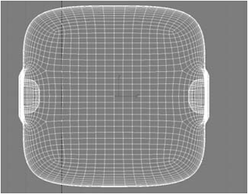
Figure 1-114
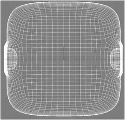
Figure 1-115
3. With the edges selected, click the Extrude Settings button and set the Height to –2 (so the edge will be pushed inward) and the Base Width to 0.08.

Figure 1-116
FYI: So why these numbers? We want a channel deep enough so it reads when you render, but not so deep that it looks cavernous. Look at objects around you. Most seams are fairly shallow. Likewise, Base Width needs to be wide enough to read, but not so wide it jacks up your model or looks weird. There’s nothing magical about my numbers. I used trial and error until I got something that looked good to me. Praise Undo! If you don’t like the seam created by my numbers, experiment with your own. Part of the fun of 3D is trying new things!
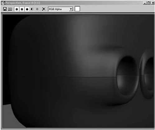
Figure 1-117
4. Switch to the Top view, switch to Polygon selection mode, select and delete the left half of the model, and add a Symmetry modifier to the stack.

Figure 1-118

Figure 1-119
5. Switch to the Perspective view, select the Edge selection mode tool, and select the edges shown (just above the socket of the first leg). Note: Make sure the edges are selected inside the socket until they reach the middle seam.

Figure 1-120

Figure 1-121
Message: The above edges have been exaggerated with a heavy outline to make them easier to see.
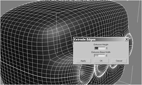
Figure 1-122
FYI: Doesn’t look like much has happened, but we want a subtle seam and not a canyon. And since we have Symmetry applied, Max has made a matching seam on the left side. To really see the seams, do a test render.
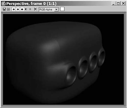
Figure 1-123
7. Switch to the Perspective view, select the Edge selection mode tool, and select the edges. Note: Make sure the edges are selected inside the socket until they reach the middle seam.
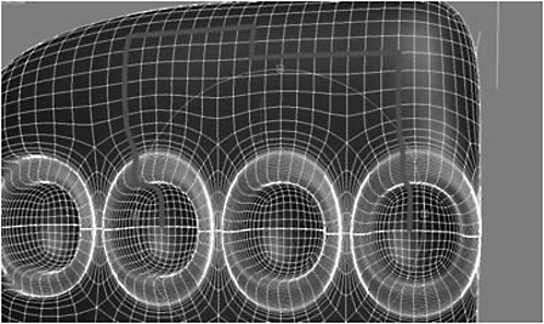
Figure 1-124
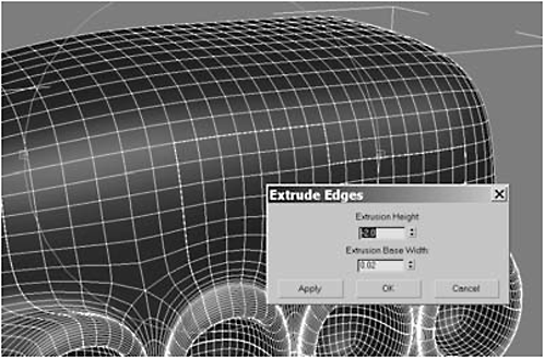
Figure 1-125
9. Select the 56 polygons shown, delete them, select the border, and Cap the hole.

Figure 1-126

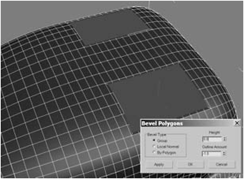
Figure 1-127

Figure 1-128

Figure 1-129

Figure 1-130
11. In Figure 1-131, the edges of the front panel have been accentuated to help you see them better. Notice the intersection highlighted with the circle. This is where we will place our first screw for mounting the panel. Find that intersection.
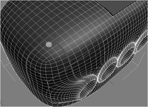
Figure 1-131
12. At that intersection, using AutoGrid, create a Sphere with a Radius of 0.9, 32 Segments, and a Hemisphere of 0.5.
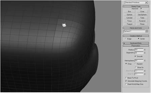
Figure 1-132

Figure 1-133
14. Convert the sphere to an Editable Polygon, rename it screw, and delete the backward-facing polygons.

Figure 1-134
15. Select the 64 polygons shown:
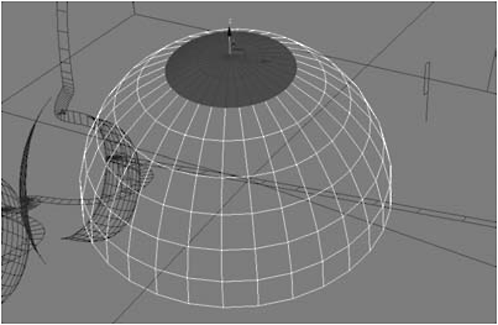
Figure 1-135
16. Click Bevel Settings and enter the values in the following table, then switch to the Move tool (W) and move the polygons –0.15 in the Z axis:
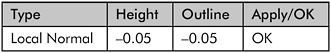

Figure 1-136

Figure 1-137
17. Click Shrink and then click Bevel Settings:

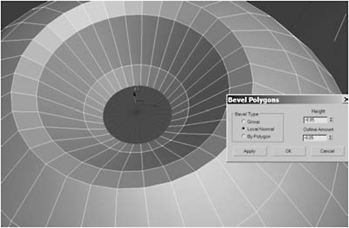
Figure 1-138
18. Select the polygons shown in Figure 1-139.

Figure 1-139
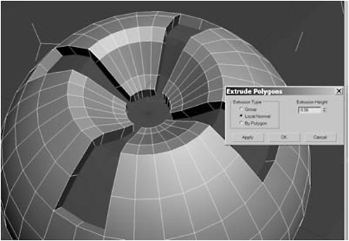
Figure 1-140
20. Extrude them by Group –0.25 and then click OK.
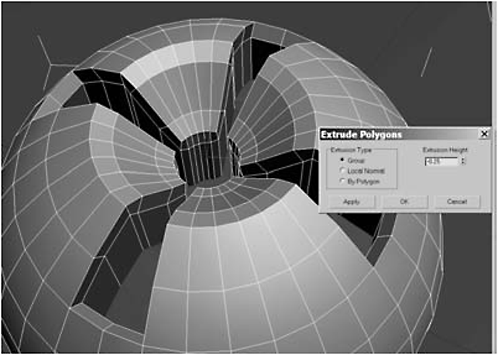
Figure 1-141
21. Click Use NURMS Subdivision and set the iterations to 0 for Display and 2 for Rendering.
Figure 1-142
22. Object-select the screw, Shift-drag to make two clones, and position them on the access panel as shown:
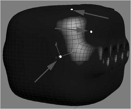
Figure 1-143
23. Object-select the screw, make six clones, and position them on the side access panel as shown:

Figure 1-144

Figure 1-145
Urgent: Notice that we have some weirdness going on with some polygons poking through the top of our model. To fix it we merely need to raise the top polygon in the Z axis.
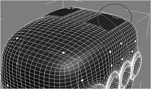
Figure 1-146
25. Highlight the cap and move it 1.0 in the Z axis.
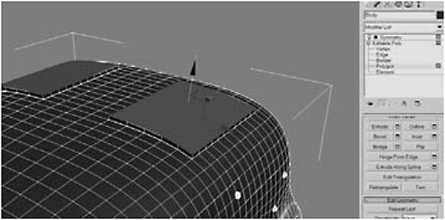
Figure 1-147

Figure 1-148
26. Select the vertices shown and then click the Connect button to connect them with an edge.
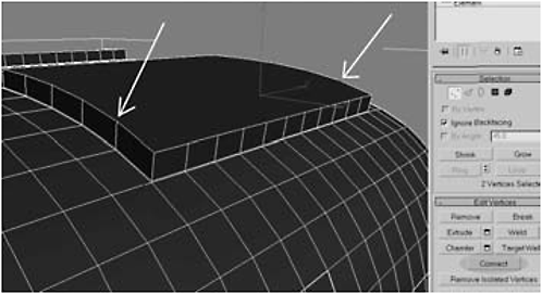
Figure 1-149

Figure 1-150
27. Repeat the last step until all the vertices (eight total) have been connected.
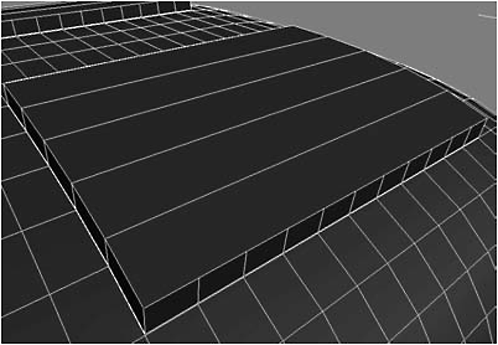
Figure 1-151
28. Use the Cut tool to split the edges in the opposite direction, and then repeat it until all the vertices have been connected.

Figure 1-152

Figure 1-153


Figure 1-154
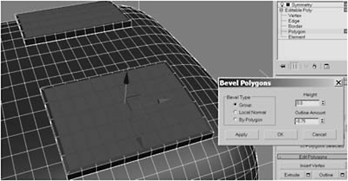
Figure 1-155


Figure 1-156
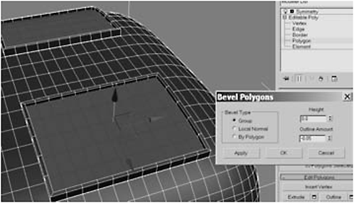
Figure 1-157

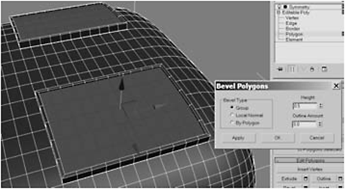
Figure 1-158

Figure 1-159


Figure 1-160
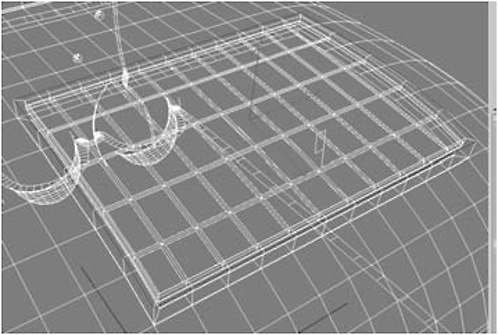
Figure 1-161

Figure 1-162
31. Chamfer the edge by 0.03 and click OK.

Figure 1-163
32. Convert the body to an Editable Polygon (to collapse the stack), select the polygons shown, and Extrude them by 1.5.

Figure 1-164
33. Switch to the Front view, select Extended Primitives under the Create panel, and click on Capsule. Create a capsule above the cradle you made in the previous step, and use the Move and Rotate tools to position it in the cradle.


Figure 1-165
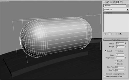
Figure 1-166
34. Convert it to an Editable Polygon, rename it tank, and Select and Link it to the body.
35. Switch to the Front view, use AutoGrid to create a Tube to surround the tank, and call it Magnet.
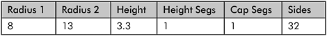
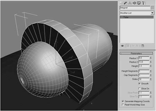
Figure 1-167
36. Shift-move the magnet in the Z axis to make a clone and position it as shown in Figure 1-168.

Figure 1-168
37. Use AutoGrid to create a Box on the front surface of the front magnet and rename it control_panel.
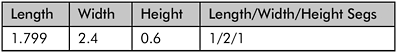

Figure 1-169
38. Convert the control_panel object to an Editable Polygon, delete the backward-facing polygons, and attach it to the magnet.
39. Using AutoGrid, create a Cylinder on the top right of the control_panel object.
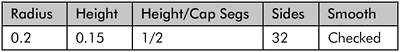

Figure 1-170
40. Convert the cylinder to an Editable Polygon and delete the bottom-facing polygons.
41. Using Edge selection mode, select and Loop the center cap segments, then right-click the Scale tool and scale them up by 160 percent.
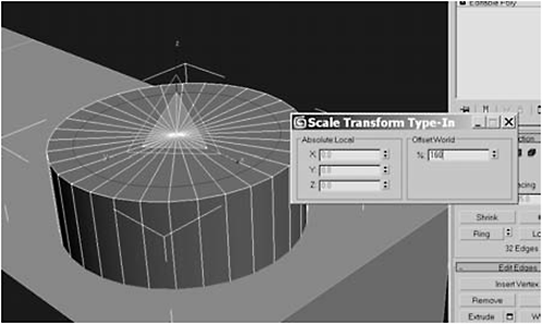
Figure 1-171

Figure 1-172

Figure 1-173
43. Change the Extrusion Height to 0.05, click Apply eight times, and then click OK.

Figure 1-174
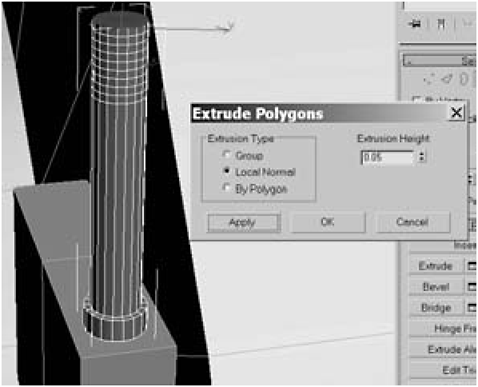
Figure 1-175
44. Click the Grow button nine times or until the top segments have all been selected.
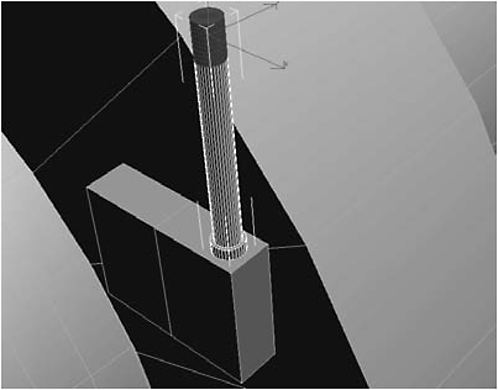
Figure 1-176
45. Add a Bend modifier to the stack, click the rollout, select the Bend modifier’s Center, and move it down in the Z axis until it is aligned with the bottom segment of the selected area.

Figure 1-177

Figure 1-178
FYI: Unfortunately, the gizmo is obscured by the selection highlighting, even if you’re in wireframe mode. However, highlighting is disabled when you use the Arc Rotate tool, and you can see an orange box (the gizmo), representing the area affected by the Bend modifier. The Bend modifier affects the selected area, which in this case is the top nine segments and not the whole object. The Bend modifier bends the geometry from the center of the gizmo; the Center is represented by yellow crosshairs. By default, it’s centered (duh), which means the selected area will bend from the center of the selection. This is not what we want. We want the bend to start from the bottommost segment (which corresponds to the bottom of the orange box) and we want its effect to extend over the entire selection area. So … we have to move the Center down to the bottom of the gizmo so the bend will start there, which corresponds to the first segment.
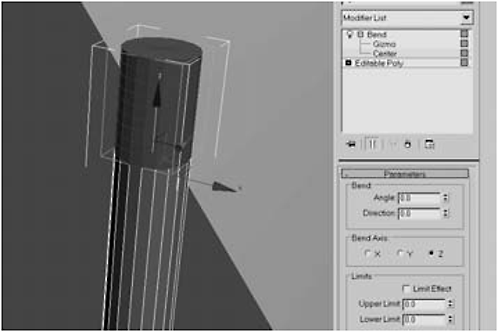
Figure 1-179
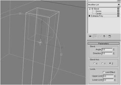
Figure 1-180
46. Under Parameters, set the Bend Angle to 77 degrees, the Direction to –90, and the B end Axis to Z.
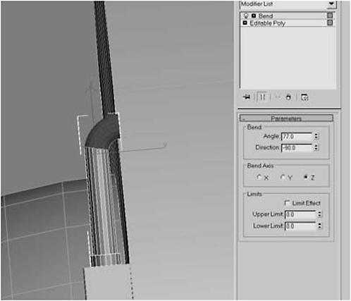
Figure 1-181
FYI: The reason the angle is 77 and not 90 is because the top of the bot is sloped and the magnets are actually tilted slightly forward, making the pipe angled slightly forward.
47. Right-click on the Bend modifier and select Collapse All to make the bend permanent; we’ll be needing to make another bend momentarily so we want a clean object.
48. Click the Shrink button until only the 18 polygons on the tip of the pipe are selected.
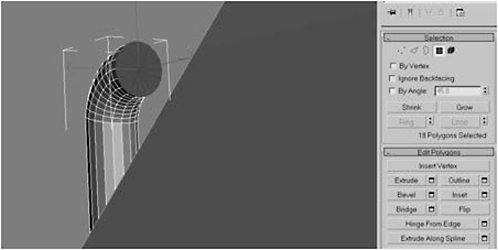
Figure 1-182


Figure 1-183
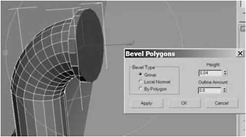
Figure 1-184
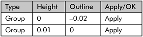

Figure 1-185

Figure 1-186
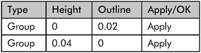
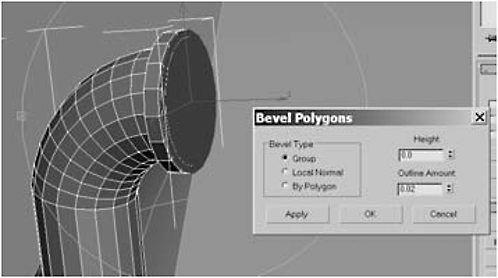
Figure 1-187

Figure 1-188
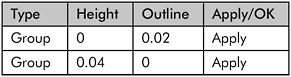
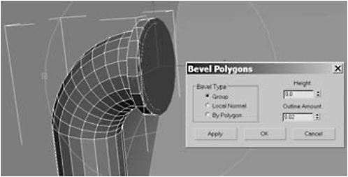
Figure 1-189
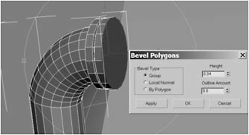
Figure 1-190


Figure 1-191
50. Extrude the polygons 12.5 or until the pipe is just shy of the mid-point of the second magnet and then hit Apply (not OK).

Figure 1-192
51. Extrude the polygons 0.05, hit Apply eight times, and then hit OK.
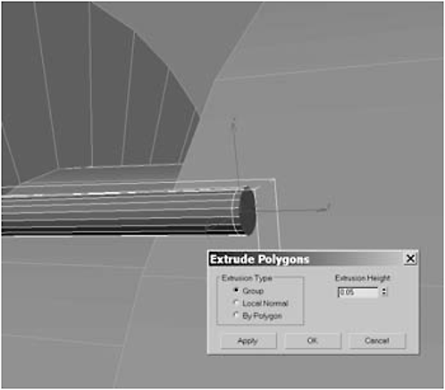
Figure 1-193

Figure 1-194
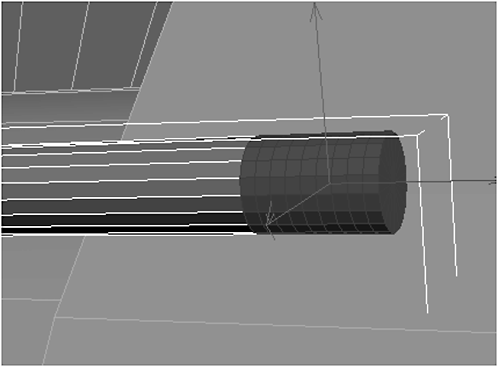
Figure 1-195

Figure 1-196
53. Move the Bend modifier’s Center to the end of the Bend modifier the way you did with the previous bend and set the Parameters to Angle –90 and Direction –26.

Figure 1-197

Figure 1-198
54. Click Shrink nine times, or until only the polygons at the tip of the pipe are selected, and then Extrude them 2.
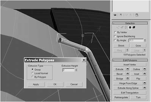
Figure 1-199
55. Click Bevel Settings:
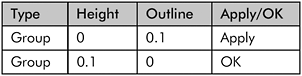

Figure 1-200

Figure 1-201
56. Hit the Delete key to delete the polygons and then, using AutoGrid, create a Box (just above the pipe) and use the Move and Rotation tools to position it as shown in Figures 1-202 and 1-203:
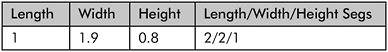
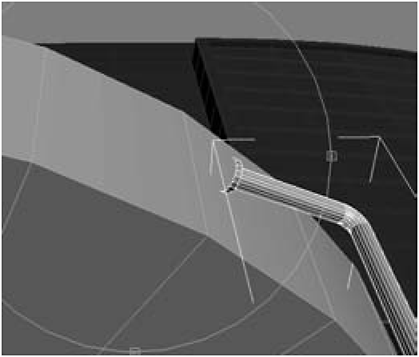
Figure 1-202
Figure 1-203
57. Convert the box to an Editable Polygon and rename it control_panel02.
58. Select the rear magnet, attach the box to it, and then object-select the pipe and attach it to either magnet.
59. Select the magnet, use Polygon Selection mode to select the upper-right quarter of control_panel02, and click Bevel Settings:

Figure 1-204
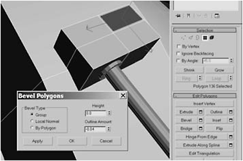
Figure 1-205
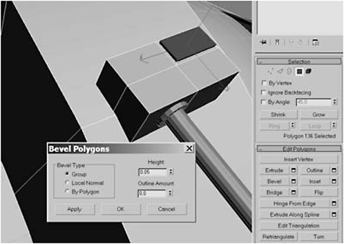
Figure 1-206
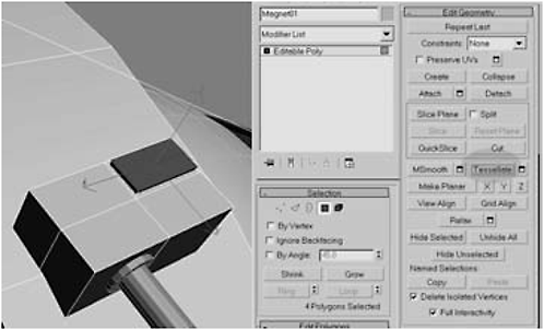
Figure 1-207

Figure 1-208
FYI: Tessellate subdivides the selected geometry each time you click the button. In this case, each time you hit the button it will subdivide each rectangular polygon into four polygons.
61. Click Bevel Settings:

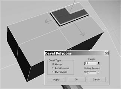
Figure 1-209

Figure 1-210

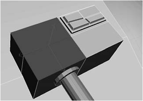
Figure 1-211
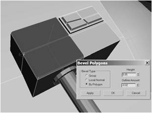
Figure 1-212
63. Switch to the front control panel, select the front two polygons, hit the Tessellate button, and then select the two polygons in the upper-right of the panel.

Figure 1-213

Figure 1-214
64. Click Bevel Settings:
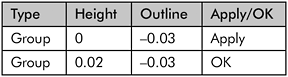
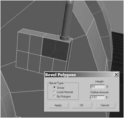
Figure 1-215

Figure 1-216
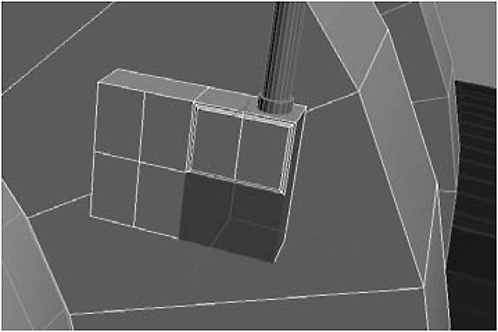
Figure 1-217
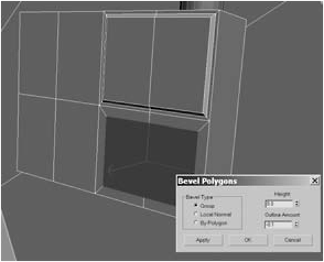
Figure 1-218
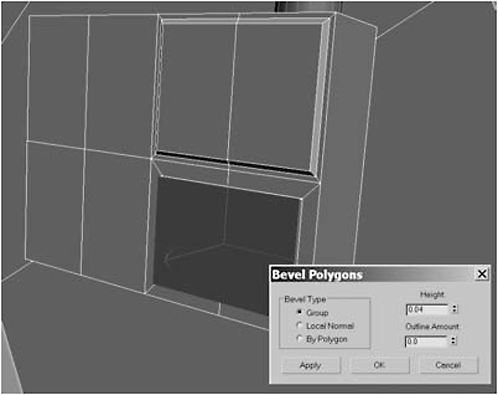
Figure 1-219
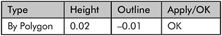
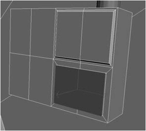
Figure 1-220

Figure 1-221
67. Select the left four polygons and click Bevel Settings:
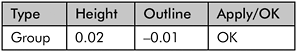

Figure 1-222
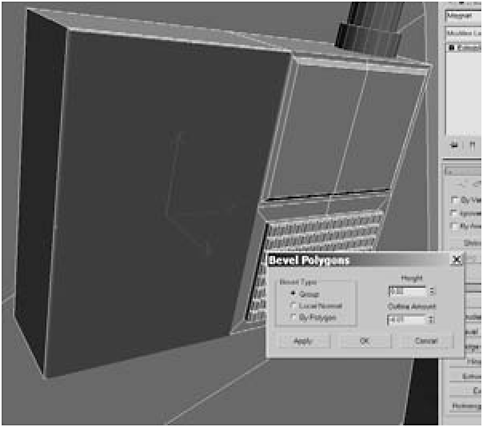
Figure 1-223
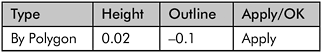

Figure 1-224

Figure 1-225
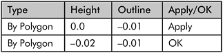
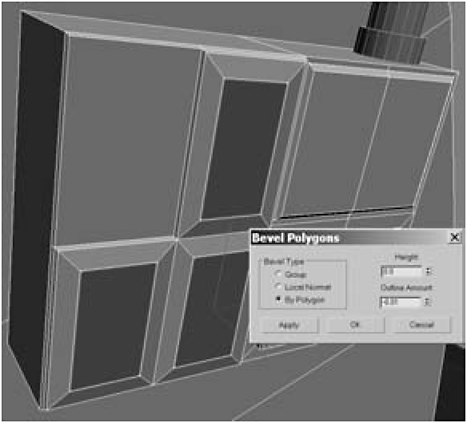
Figure 1-226

Figure 1-227
69. Hit the Tessellate button four times and then click Bevel Settings:
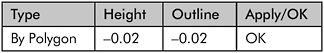

Figure 1-228


Figure 1-229
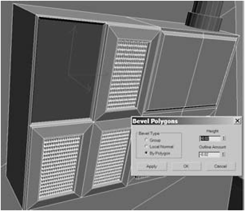
Figure 1-230

Figure 1-231

Figure 1-232
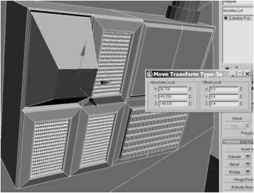
Figure 1-233
72. Click Bevel Settings:

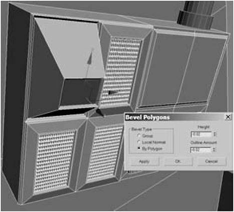
Figure 1-234
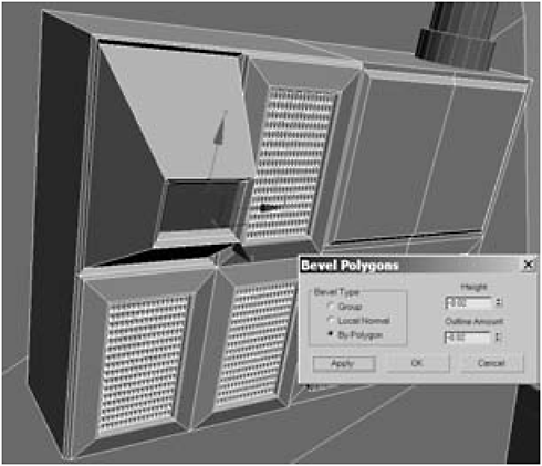
Figure 1-235

Figure 1-236
73. Under Edit Polygons, click the Hinge From Edge Settings button, and enter –90 for the Angle and 9 for Segments. Click the Current Hinge button and select the edge shown in Figure 1-238 (the edge is exaggerated to make it easier to see).
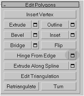
Figure 1-237

Figure 1-238
FYI: Hinge From Edge creates new polygons from the edge you select at the angle you specify. The number of segments you enter determines how many polygons are created by the hinge. The more segments you enter, the more curve the final geometry will have. In our case, we wanted to create an air intake that curved back into the geometry, so we used a negative angle. Since that angle was 90 degrees, I used nine segments, which means new geometry would be created at 10-degree increments, creating an ice curve.
74. Extrude the polygon –0.065 and then delete the polygon since you can’t see it (it’s inside the model).
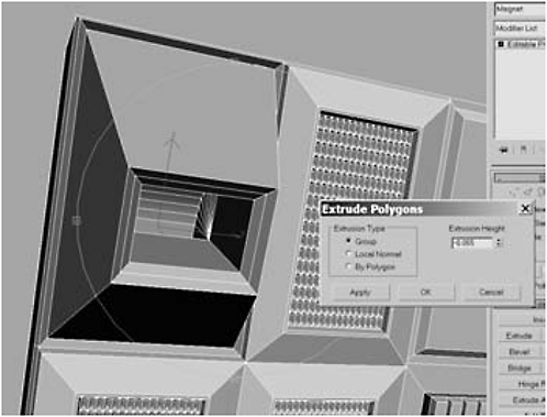
Figure 1-239
Day 4: Wiring the Eyes
1. Arc Rotate around the front, select the centermost polygons (96 total) on the front center of the tank, and Extrude them by 33.Then click Bevel Settings:
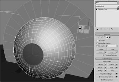
Figure 1-240
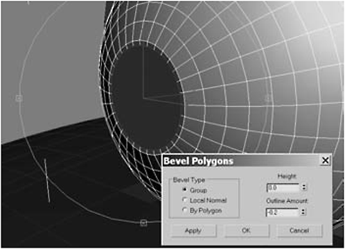
Figure 1-241
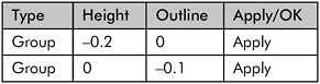
Figure 1-242

Figure 1-243

Figure 1-244
2. Using AutoGrid, create a Tube in the center of the sphere.

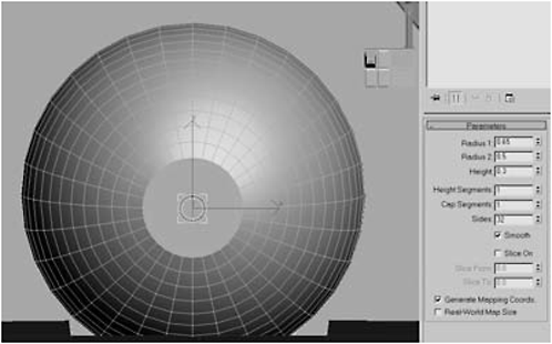
Figure 1-245
3. Convert the tube to an Editable Polygon, name it socket, and delete the backward-facing polygons.
4. Hold down the Shift key and drag in the X axis to create a clone.
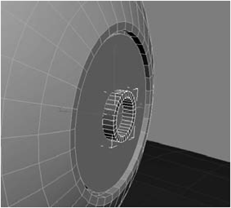
Figure 1-246
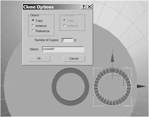
Figure 1-247
5. Scale down the clone to between 20 and 30 percent of the original (pick a size you like) and then create a clone of it to the left of the original and set the Number of Copies to 5.
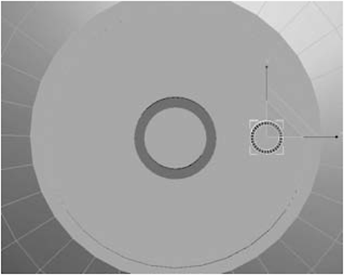
Figure 1-248

Figure 1-249
6. Position the clones as shown, select them, then use Select and Link to link them to the tank.

Figure 1-250
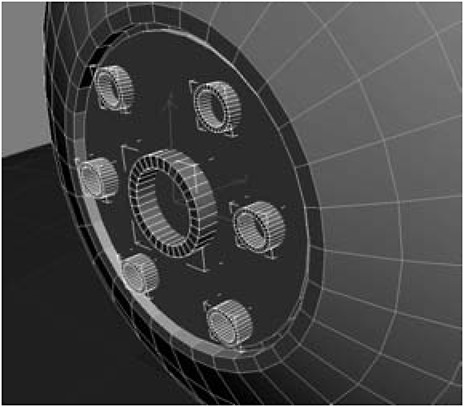
Figure 1-251
7. Unhide the eye assemblies, select the large middle one, click the Group menu item, and select Open (to allow you to edit the individual components).
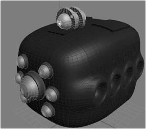
Figure 1-252
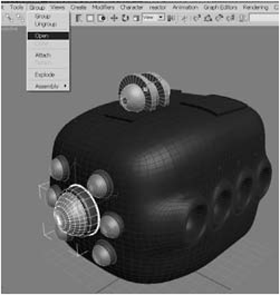
Figure 1-253
8. Under the Create panel, select Extended Primitives, click the Hose button, and draw out a hose in the Perspective viewport (don’t worry about the dimensions — they’re irrelevant in this case).

Figure 1-254
FYI: Take a breath. I know there are a lot of controls for Hose, but like the million or so gauges on a 767, most of them you’ll never use. The “master” control, so to speak, is the End Point Method. What you select will determine which of the other controls you’ll use. You can either make a free hose (meaning you can move it wherever you like), or you can make a hose that is bound to objects. Think of a bound hose as being the type of hose that’s under the hood of your car. Both ends are attached to something. When you select the bound type, you’ll pick two objects that the hose will connect (i.e., bind to) with (i.e., binding objects): the top object and the bottom object. Top and bottom are a bit misleading, since the objects can actually be side by side or front to back. Once you select the objects the hose will be bound to, you’ll then adjust the tension on each end, which will determine the overall shape of your hose. Is it tightly wrapped like a rubber band, or is it loose and flexible like a garden hose? The greater the tension, the closer the hose will be pulled toward the binding object. Now … that wasn’t so bad, was it?
9. Select Bound to Object Pivots as the End Point Method. Under Binding Objects, click the Pick Top Object button, hit the H key to open the selection list, pick socket from the list, and then click OK.

Figure 1-255
Fire Drill: Nothing happened! What gives? Nothing will happen until you select the bottom binding object. At that point, the hose will jump to the connections, and then the fun really begins.
10. Click the Pick Bottom Object button, hit the H key to open the selection list, pick eye_socket from the list, and then click OK.
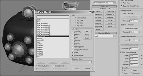
Figure 1-256

Figure 1-257
Fire Drill Oh … that looks much better. Thanks for nothing! The reason the hose looks like a mess is because 1) its diameter is too big for the model and it needs to be resized, and 2) we haven’t adjusted the tension yet. No worries, mate.
11. Set the Top Tension to 48 and the Bottom Tension to 2.0; this disparity will make the hose flexible enough to curve around the front of the bot. Next, under Common Hose Parameters, set the Segments to 34, check the Flex Section Enable box, set the Starts to 30,settheEndsto66, set Cycles to 24, and set the Diameter to 94. Finally, under Hose Shape choose Round Hose with a Diameter of 0.93 and 16 Sides.
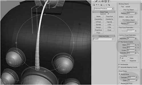
Figure 1-258
FYI: Even though there is a Hose Shape setting, the Common Hose Parameters settings are what determine the hose’s “shape.” It’s really hard to explain the effect of any given control, as the interactions of the controls determines the overall shape. Changing any given control can give you a radically different looking hose. The best way to learn is to fiddle with the controls. The values I used were the result of trying different values until I found a set I liked. I wanted my hoses to represent wires, and as such I wanted them to be smoothish. Play around with the different controls until you find a shape that you like. Go ahead. I’ll wait.
12. Hit the H key, select eye_assembly02, and open the group.

Figure 1-259
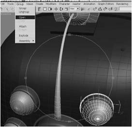
Figure 1-260
13. Create a hose, set the End Point Method to Bound to Object Pivots, click Pick Top Object, hit H, select socket04 (your actual numbers may differ depending on how you arranged the clones), click Pick Bottom Object, hit H, and select eye_socket02 from the list.
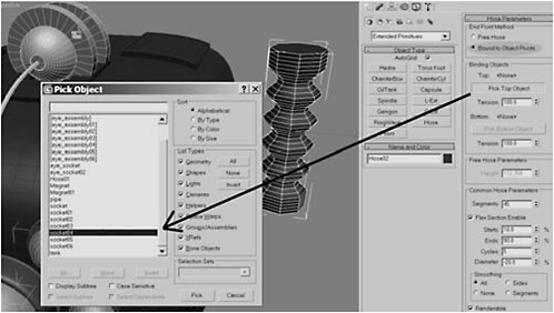
Figure 1-261

Figure 1-262
14. Set the Tensions, Common Hose Parameters, and Hose Shape settings the way you did in step 11. You might consider using different shapes for each eye. I chose to make narrower hoses for the smaller eyes, but feel free to go crazy.
15. Wire the eye at the three o’clock position the same way you wired the last two eyes.
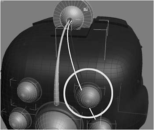
Figure 1-263
Fire Drill: Whoops! What just happened? Why is my three o’clock eye going through my one o’clock eye? If you look closely at the End Point Method setting, you’ll see that it actually says Bind to Object Pivots. The hose is not really bound to the object at all, but rather to its pivot points. Since an object’s pivots start out centered to the object, the hose will attach there. Unfortunately for us, the arrangement of our eyes ensures that the hoses for the lower eyes will cross through the centers of the eyes above them. Fortunately, since the eyes will not be moving, moving their pivots won’t affect anything other than the curvature of the hose.
16. Select the eye_socket, click the Hierarchy tab, click Affect Pivot Only, and use the Move tool to reposition the pivot until the hose no longer penetrates the eye above it. (I found moving the pivot to the left side of the eye socket fixed the problem and ended up looking really cool.)
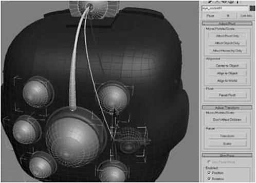
Figure 1-264

Figure 1-265
Fire Drill: When you move the pivot point of one or both binding objects, you’ll probably need to reset your hose’s tension settings.
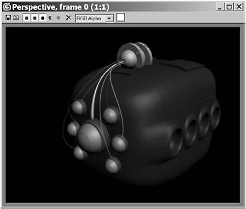
Figure 1-266
Day 5: Refining the Middle Leg and Adding the Hydraulic Pump
1. Unhide the leg.
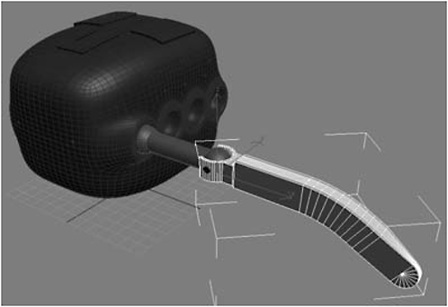
Figure 1-267
2. Select the vertices making up the tip of the leg and scale them to 80% of their size.
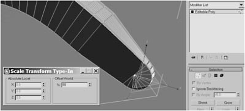
Figure 1-268

Figure 1-269
4. Right-click the Scale tool, select Non-uniform Scale, and enter 90 into Offset World Y axis.
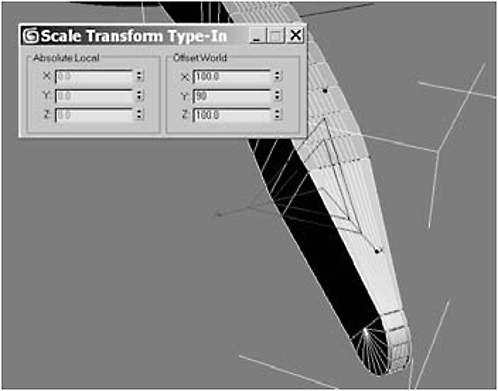
Figure 1-270
5. Select the next row up and Non-uniform Scale them to 95 in the Y axis.
Figure 1-271
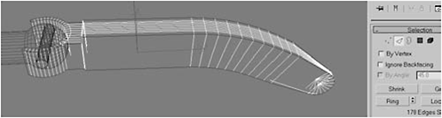
Figure 1-272
7. Chamfer the edges by 0.2 to create a more refined edge.
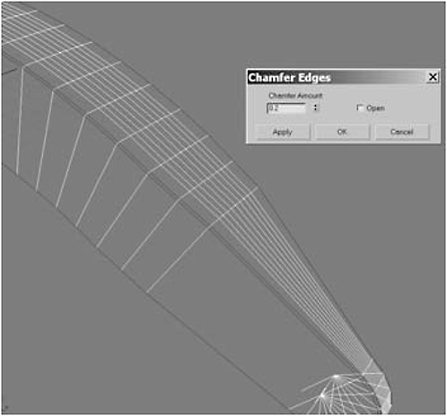
Figure 1-273
8. Select the four polygons shown in Figure 1-274 and Extrude them by 6.

Figure 1-274

Figure 1-275

Figure 1-276
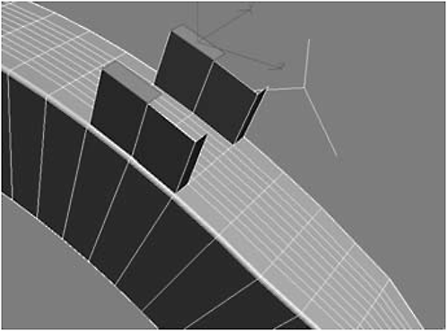
Figure 1-277
10. Select one of the remaining upper polygons, click Hinge From Edge, set the Angle to 183.5, set the Segments to 10, click Pick Hinge, click the poly’s bottom edge, and then delete the backward-facing polygon. Repeat on the other side and then weld the vertices.

Figure 1-278
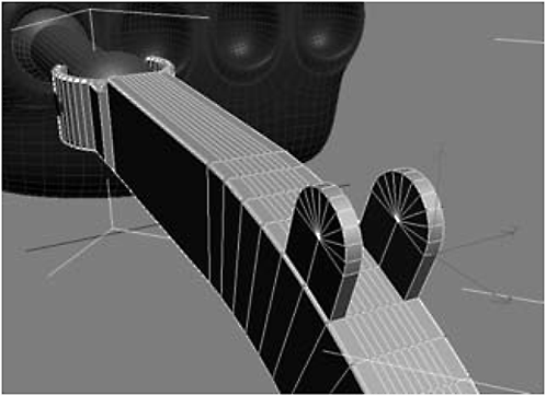
Figure 1-279
11. Using AutoGrid, create a Tube around the middle of the upper leg.


Figure 1-280

Figure 1-281

Figure 1-282
13. Non-uniform Scale the top polygons down to 0 in the Z axis, and then Extrude them by 5 three times.

Figure 1-283
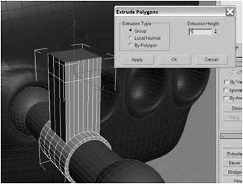
Figure 1-284
14. Select the four polygons shown and Extrude them by 5.

Figure 1-285
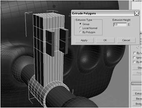
Figure 1-286
15. Select the bottom two polygons and delete them. Select the top polygon, Hinge From Edge 180 degrees with 10 segments, and delete the backward-facing polygon. Repeat for the other side.
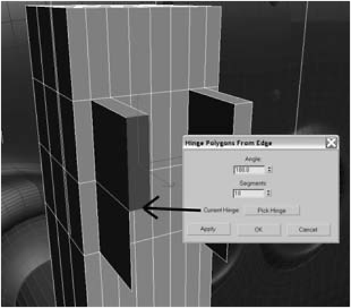
Figure 1-287

Figure 1-288
16. Select the vertices and Weld them. Then select the 27 top edges shown in Figure 1-290.
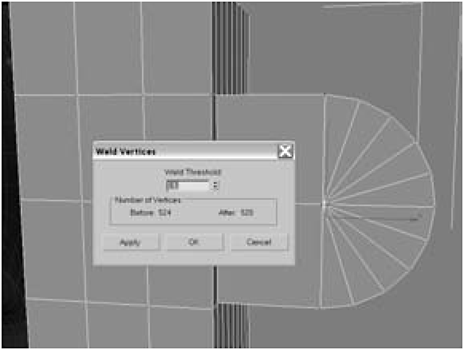
Figure 1-289

Figure 1-290
17. Click Connect, switch to the Top view, and select the middle 16 polygons on the top.
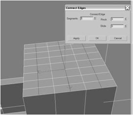
Figure 1-291
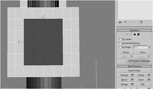
Figure 1-292

Figure 1-293

Figure 1-294
19. Press Cap to fill the hole with a single polygon, select the polygon, click the Tessellate button to tessellate the polygon, switch to Vertex selection mode, and select the middle vertex.

Figure 1-295
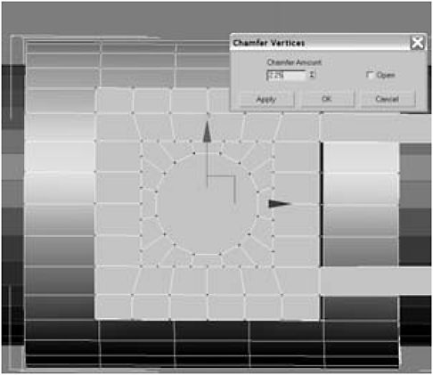
Figure 1-296
20. Chamfer the vertex by 2.25 to create a circular polygon from the square. Select the circular polygon.
Figure 1-297
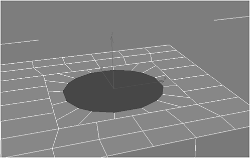
Figure 1-298

Figure 1-299

Figure 1-300
Figure 1-301

Figure 1-302
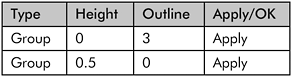
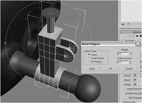
Figure 1-303

Figure 1-304
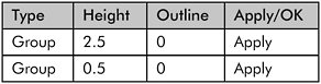
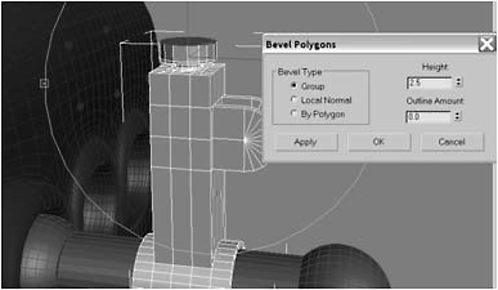
Figure 1-305
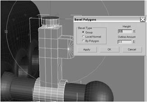
Figure 1-306


Figure 1-307

Figure 1-308

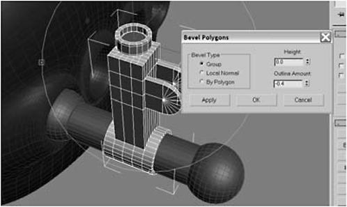
Figure 1-309
22. Select the five middle polygons facing back toward the body and Extrude them 5.

Figure 1-310
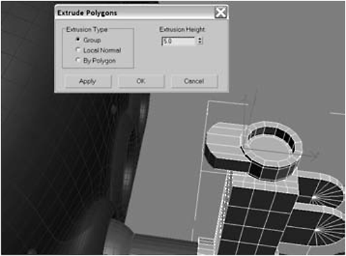
Figure 1-311
23. Non-uniform Scale the polygons down to 0 in the X axis and then delete them.
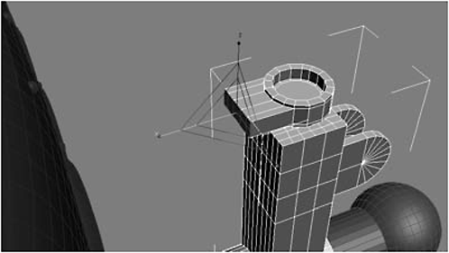
Figure 1-312
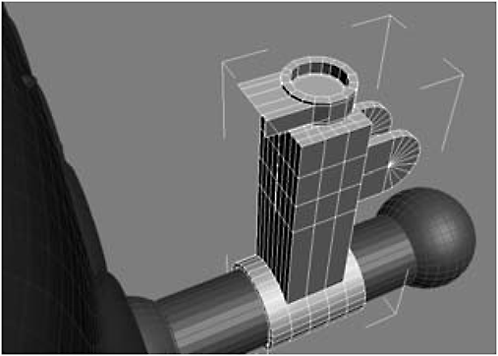
Figure 1-313
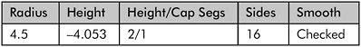
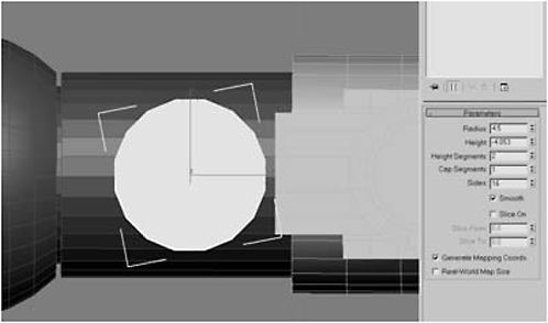
Figure 1-314
25. Select the middle edge and Chamfer it by 1.3.
Figure 1-315
26. Select the middle five polygons that face the hydraulic system and Extrude them by 3.2.
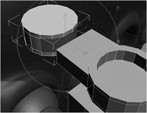
Figure 1-316

Figure 1-317
27. Use the Non-uniform Scale tool to flatten the polygons by scaling them down to 0 in the X axis.
28. Select the hydraulic system, click Attach List, and select Cylinder01 to attach it. Then Weld the vertices together along the seam.
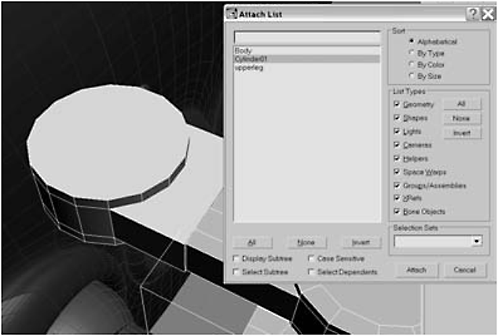
Figure 1-318
29. Select the top polygon shown in Figure 1-319 and then click Bevel Settings:


Figure 1-319

Figure 1-320

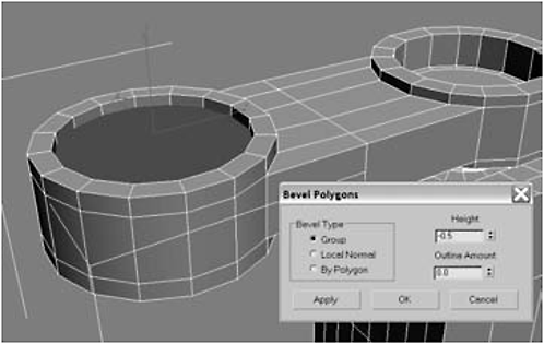
Figure 1-321

Figure 1-322


Figure 1-323

Figure 1-324

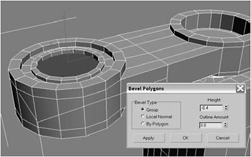
Figure 1-325


Figure 1-326
31. Convert the cylinder to an Editable Polygon, delete the back-facing polygon, and use the Cut tool to make the cuts shown.

Figure 1-327
32. Select the two outer polygons and Extrude them 0.4 to create a screw.
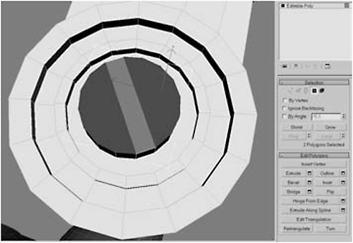
Figure 1-328

Figure 1-329
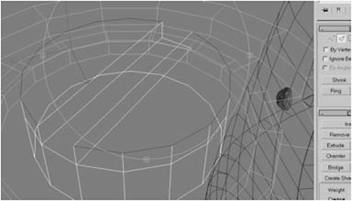
Figure 1-330

Figure 1-331
34. Chamfer the edge by 0.03 and then click OK.
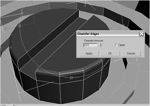
Figure 1-332
35. Add a Smooth modifier to the screw’s stack, click Auto Smooth, collapse the stack, and Select and Link the screw to the hydraulic pump.
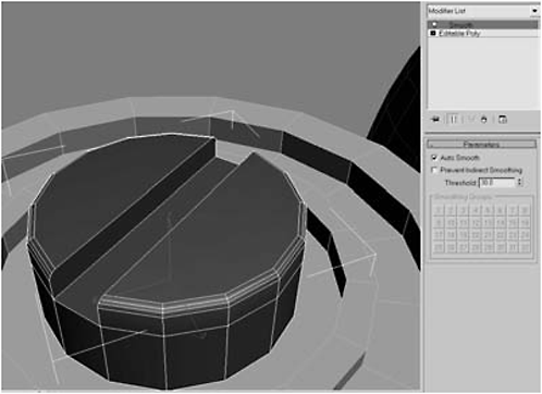
Figure 1-333

Figure 1-334

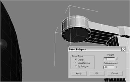
Figure 1-335
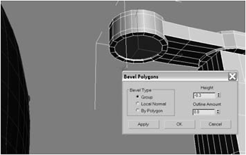
Figure 1-336

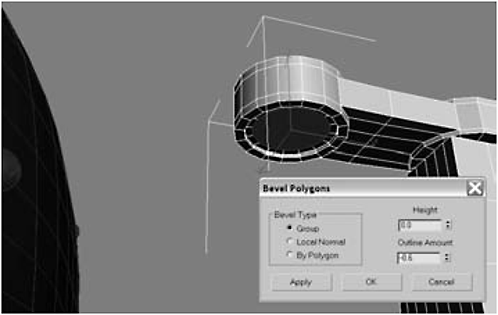
Figure 1-337
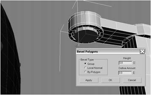
Figure 1-338


Figure 1-339
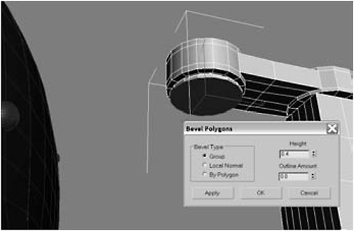
Figure 1-340
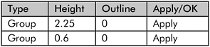
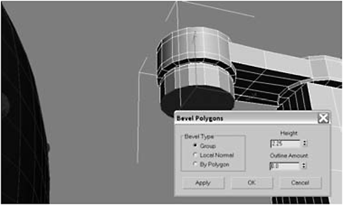
Figure 1-341
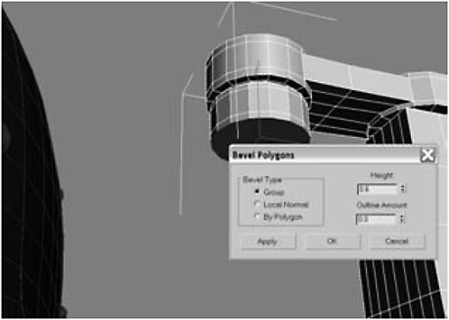
Figure 1-342
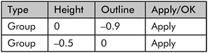

Figure 1-343

Figure 1-344

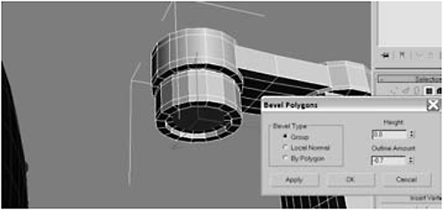
Figure 1-345
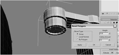
Figure 1-346
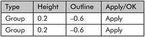
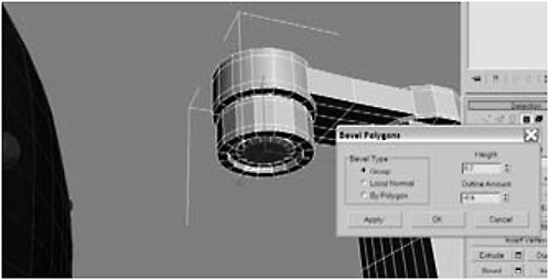
Figure 1-347
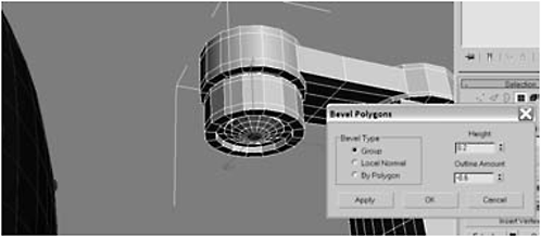
Figure 1-348
38. Select the three polygons shown and Extrude them by 11.

Figure 1-349
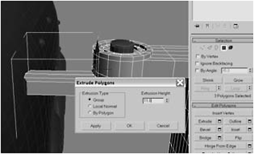
Figure 1-350
39. Non-uniform Scale the polygons to 0 in the X axis, delete the polygons, border-select the resulting hole, and use the Move tool to move the border in the X axis until it is flush with the body.
Figure 1-351
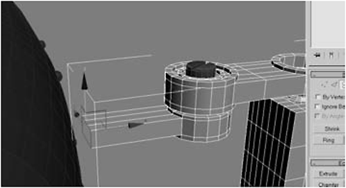
Figure 1-352
40. Use the Rotate tool to adjust the border until it is evenly flush against the surface of the body, click the Create Shape From Selection button, and name the resulting shape leg_seal:

Figure 1-353

Figure 1-354
41. Hit the H key and select leg_seal from the list. Under Rendering, click Enable In Renderer, Enable In Viewport, Generate Mapping Coords, and Radial. Set Thickness to 2, Sides to 12,and Angle to 0.
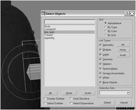
Figure 1-355

Figure 1-356
42. Select and Link the seal to the body and hit F9 to do a test render of the hydraulic system.

Figure 1-357
43. Use AutoGrid to create a Gengon on top of the hydraulic system.


Figure 1-358
44. Convert the gengon to an Editable Polygon and delete the downward-facing polygon.
45. Using AutoGrid, create a Cylinder on top of the gengon you just created. Convert it to an Editable Polygon and delete the downward-facing polygon.

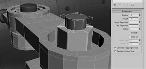
Figure 1-359
46. Hit the H key, select the gengon and the cylinder from the list, and then use Select and Link to link them to the hydraulic system.

Figure 1-360
47. With the gengon and cylinder still selected, hold down the Shift key and use the Move tool to create four clones on top of the body.

Figure 1-361
48. Arrange the four clones on top of the body as shown, with the surface just beneath the body’s surface, then use Select and Link to attach them to the body.

Figure 1-362
49. Border-select the bottom border of the gengon, click Create Shape From Selection, and name it hydraulic_seal.

Figure 1-363

Figure 1-364
50. Hit the H key, select hydraulic _seal, and enable the shapes in the renderer and the viewport. Set Thickness to 0.8, Sides to 12, and Angle to 0.
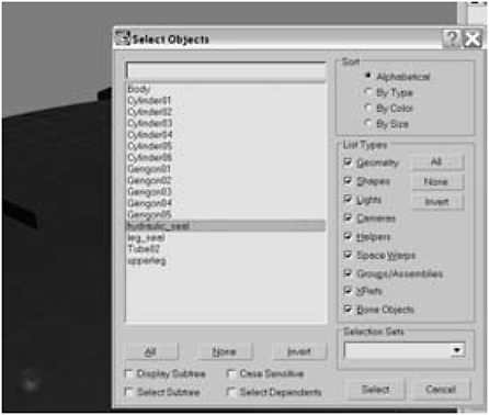
Figure 1-365

Figure 1-366
51. Use the Rotation and Move tools so that the seals are evenly flush against the body. Hit H to select the 12 objects that make up the four hydraulic connections.
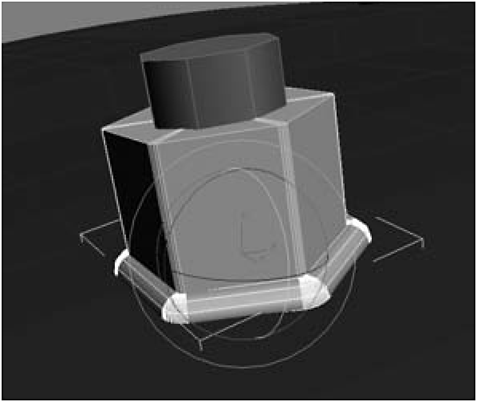
Figure 1-367

Figure 1-368
52. Use the Mirror tool to create clones on the left side of the body (you’ll need to use an offset of around –52.6), then hit the H key, select all the hydraulic connections, and Link them to the body.
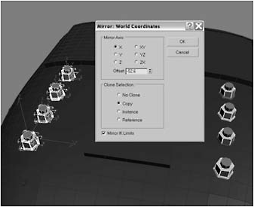
Figure 1-369

Figure 1-370
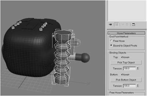
Figure 1-371
54. Click Pick Top Object, hit the H key, and click the cylinder on top of the front hydraulic connection. Next, click the Pick Bottom Object button, hit H, and then pick the cylinder that is on top of the gengon that is a top the hydraulic cylinder.

Figure 1-372

Figure 1-373
55. Set the Top Tension to 60, the Bottom Tension to 40, and the Segments to 91, and choose Flex Section Enable. Set the Starts to 2, the Ends to 99, the Cycles to 26, and the Diameter to 70. Under Hose Shape, click Round Hose, and set Diameter to 3 and Sides to 16.

Figure 1-374

Figure 1-375
57. Select the two polygons on the front of the hydraulic pump as shown in Figure 1-376.

Figure 1-376
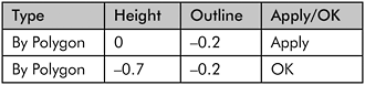
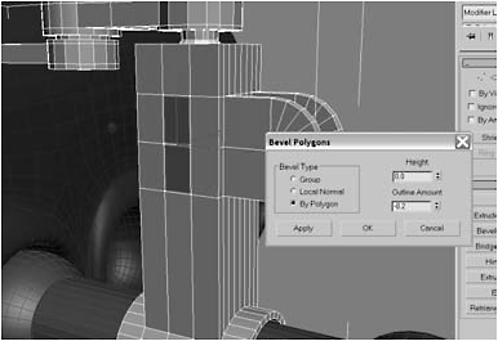
Figure 1-377

Figure 1-378
59. Turn on Use NURMS Subdivision. Click MSmooth, accept the default settings, and click OK.
Figure 1-379
Figure 1-380
60. Click Grow to increase the selection.

Figure 1-381
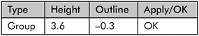

Figure 1-382
62. Click the Shrink button to choke the selection.

Figure 1-383

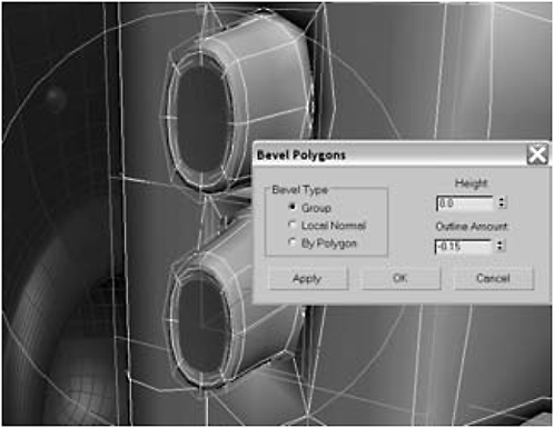
Figure 1-385

Figure 1-384

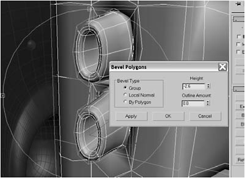
Figure 1-386
64. Delete the polygons, border-select the holes, and click Cap.
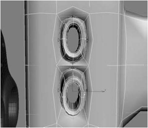
Figure 1-387
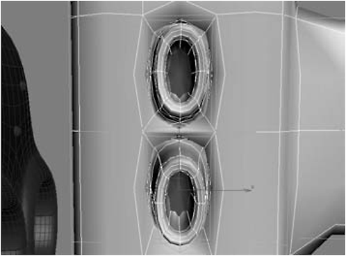
Figure 1-388
65. Click Detach, rename the objects hydraulic_anchor and hydraulic_anchor2, and then use Select and Link to link them to the hydraulic pump.
FYI: Okay. Why did we do step 64 if we’re going to just turn around and undo it in step 65? Well … strictly speaking, we didn’t. We needed the internal polygons to be separate objects for a later step when we create the hydraulic hoses. These polygons will be the upper objects we’ll link the hoses to the leg with.

Figure 1-389
Day 6: Creating the Claw and Connecting the Hydraulics to the Legs
1. Create a Cylinder inside the tip of the middle leg.
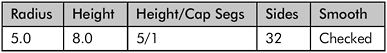

Figure 1-390
2. Convert the cylinder to an Editable Polygon, select the 12 polygons facing away from the tip of the leg on both sides of the cylinder, and Extrude them by 5.
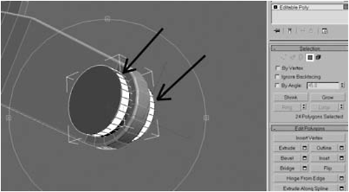
Figure 1-391

Figure 1-392
3. Use the Scale tool to scale the polygons down to 0 in the Local Z axis and select the 12 inner polygons on both sides.
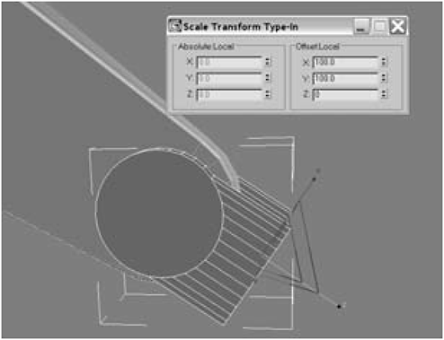
Figure 1-394

Figure 1-393
4. Extrude the polygons by 2.4, delete the polygons, and Weld the vertices together.

Figure 1-395
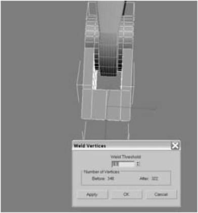
Figure 1-396
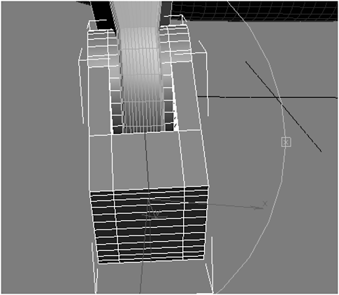
Figure 1-397

Figure 1-398
6. Select the two edges shown in Figure 1-399 and click Connect, and then do the same thing for the other side. Select the four polygons shown in Figure 1-400.
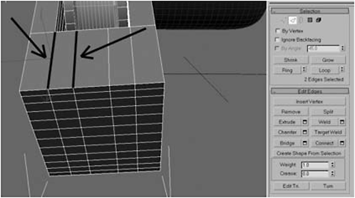
Figure 1-399

Figure 1-400
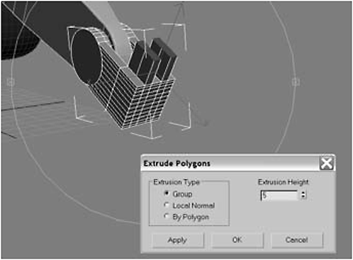
Figure 1-401

Figure 1-402
8. Click the top polygon and choose Hinge From Edge with Angle set to 180 degrees and Segments set to 10. Delete the backward-facing polygon and Weld the resulting vertices together. Then repeat it for the other side.
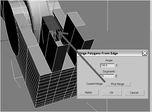
Figure 1-403
9. Click the 24 polygons on the front edge, Extrude them by 3, and hit Apply (not OK).
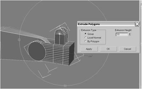
Figure 1-404

Figure 1-405
11. Click Grow 10 times, add a Taper modifier to the stack, then select Gizmo.

Figure 1-406
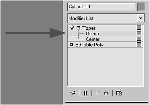
Figure 1-407
12. Use the Rotate gizmo to make the Z axis face backward and the X axis face away from the body. Scale the gizmo to be the same size as the selected area, and set the Taper Amount to–1.8, the Taper Axis Primary to X, and the Taper Axis Effect to ZY. Then collapse the stack.
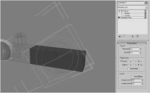
Figure 1-408
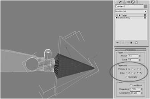
Figure 1-409
13. Click Grow until the selected polygons form an arrow head as shown. Click Detach to detach it as an object.

Figure 1-410
14. Add a Bend modifier to the object’s stack. Position and scale the gizmo so it encompasses only the triangular portion. Click the center and move it so the center is positioned on the left edge of the gizmo. Also, be sure the axes are positioned as you see them in Figure 1-411. If not, use the Rotate tool to align them as shown.
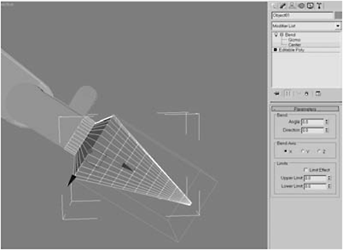
Figure 1-411
15. Set the Bend Angle to 90, the Direction to –180, and the Bend Axis to X. Click Limit Effect and set the Upper Limit to 45. Collapse the stack.

Figure 1-412
16. Select the joint part of the claw, which you detached from, hit the Attach List button, and select Object01 (or whatever you called the part you detached and bent). Click Attach.

Figure 1-413
17. Vertex-select the vertices along the seam and Weld them.
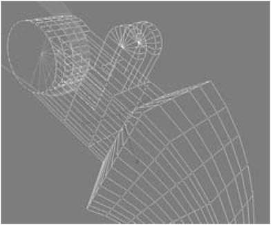
Figure 1-414
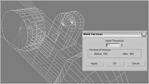
Figure 1-415
18. Select the polygons on the front and rear of the joint.
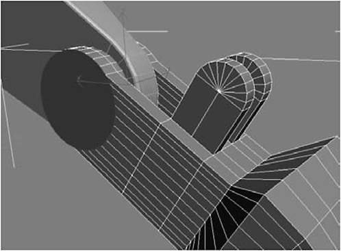
Figure 1-416


Figure 1-417

Figure 1-418
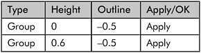
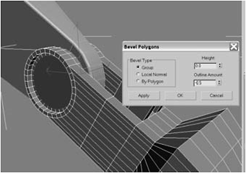
Figure 1-419
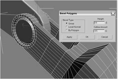
Figure 1-420

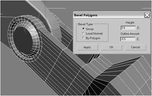
Figure 1-421

Figure 1-422


Figure 1-423
20. Create a Cylinder using AutoGrid on top of the joint of the hydraulic pump and then convert it to an Editable Polygon. Move it into position inside the joint.
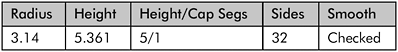

Figure 1-424
21. Select the middle 15 polygons shown in Figure 1-425, delete them, border-select the hole, and Cap it.

Figure 1-425

Figure 1-426
22. Select the cap, click the Tessellate Settings button, click Face, and then click OK. Switch to Vertex selection mode and click the middle vertex.

Figure 1-427

Figure 1-428
23. Chamfer the vertices by 1.39, select the same polygons, and Scale the polygons down to 0 in the Z axis.
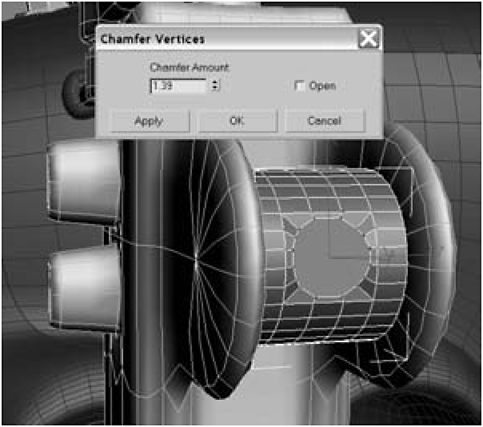
Figure 1-429
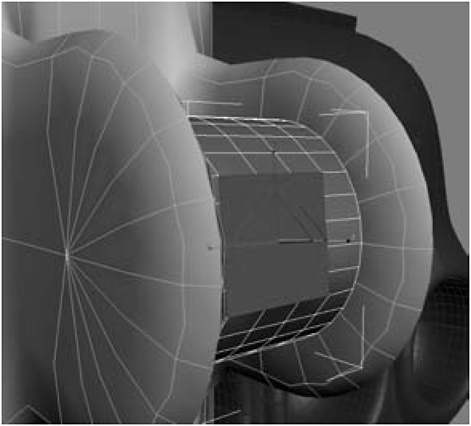
Figure 1-430
24. Click Shrink so that only the round polygon is selected, and click Bevel Settings:
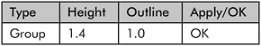
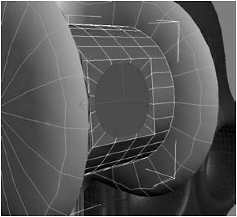
Figure 1-431
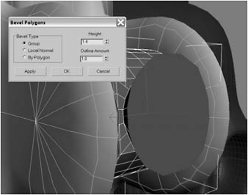
Figure 1-432
25. Delete the polygon.
26. Create a Cylinder as shown, convert it to an Editable Polygon, and delete the backward-facing polygon.

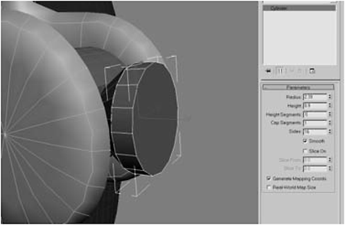
Figure 1-433
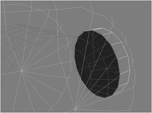
Figure 1-434
27. Click the axle, click Attach List, attach the cylinder, and turn on Use NURMS Subdivision, then set the Display Iterations to 1 and the Render Iterations to 3.
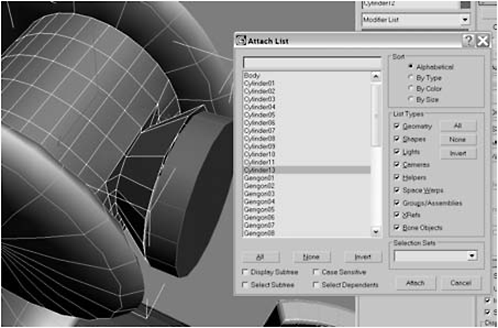
Figure 1-435

Figure 1-436
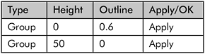
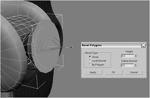
Figure 1-437
Figure 1-438
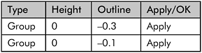
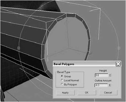
Figure 1-439
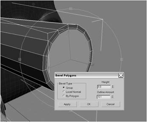
Figure 1-440


Figure 1-441

Figure 1-442
29. Detach the polygon, rename it shaft, and then use the Move tool to move it in the Z axis into position above the joint stanchions of the middle leg.

Figure 1-443

Figure 1-444
30. Click Bevel Settings:
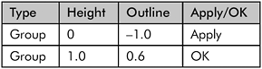

Figure 1-445

Figure 1-446
31. Create a Cylinder between the stanchions on the middle leg, convert it to an Editable Polygon, then Shift-drag to create a clone on the other side of the stanchion.

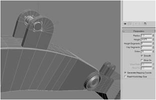
Figure 1-447
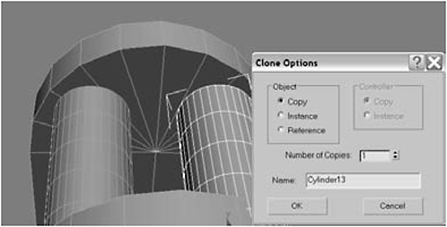
Figure 1-448
32. With both cylinders selected, open the Hierarchy tab, click Affect Pivot Only and Center to Object to center the pivots. Select the 15 polygons shown on the body side of the cylinder.

Figure 1-449

Figure 1-450
33. Delete the polygons and Cap the border. Then, using the Non-uniform Scale tool, scale the cap in the X and Y axes until you get a selection that is roughly square.

Figure 1-451
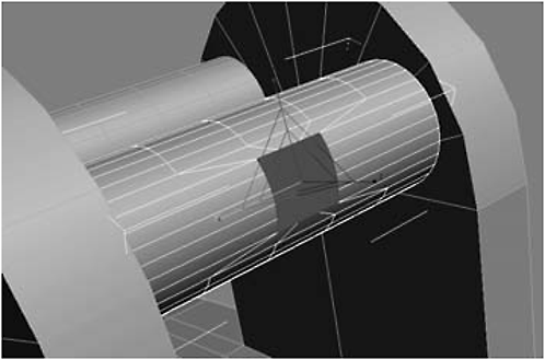
Figure 1-452
34. Tessellate the cap, choosing Face as the Type, and then Non-uniform Scale it down to 0 in the Z axis.

Figure 1-453

Figure 1-454
35. Vertex-select the middle vertex and Chamfer the vertices by 0.58. Select the polygon.
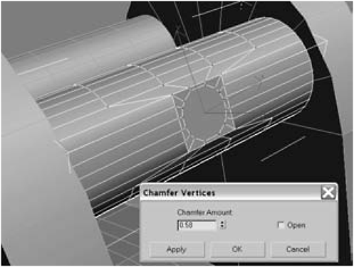
Figure 1-455
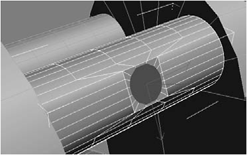
Figure 1-456

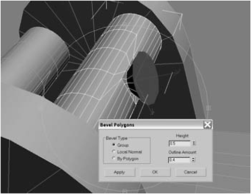
Figure 1-457
37. Using AutoGrid, create a Cylinder, convert it to an Editable Polygon, and delete the back-facing polygon.
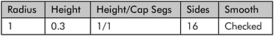
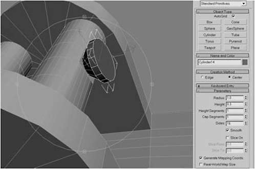
Figure 1-458

Figure 1-459
39. Select the shaft and center its pivot, then move it down to meet the axle on the middle leg.
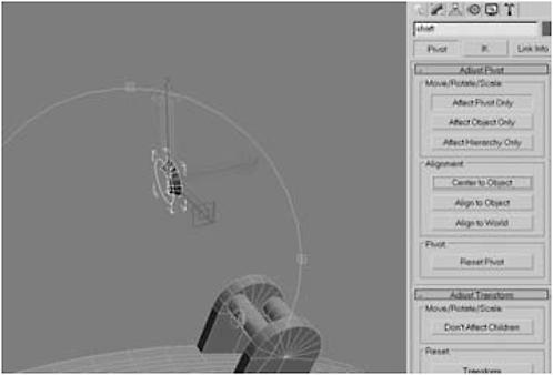
Figure 1-460

Figure 1-461
40. Border-select the open part on the axle on the middle leg. Scale it and the open part of the shaft until they fit. Attach the shaft to the axle.
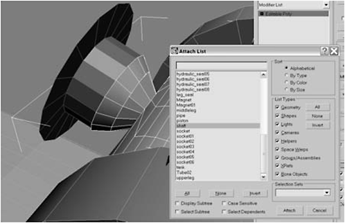
Figure 1-462
41. Border-select the open part on the shaft/axle that faces the body and Extrude it about 40 to 50. (At this point the extrusion just has to be long enough to fit around halfway into the piston attached to the hydraulic system; you can size it to fit later.)
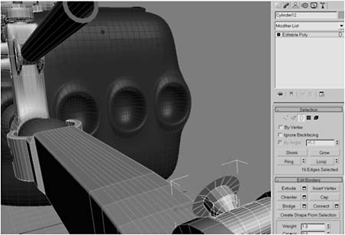
Figure 1-463
42. Set the pivots for the piston and the shaft so they are centered as shown, with their X axes facing each other.
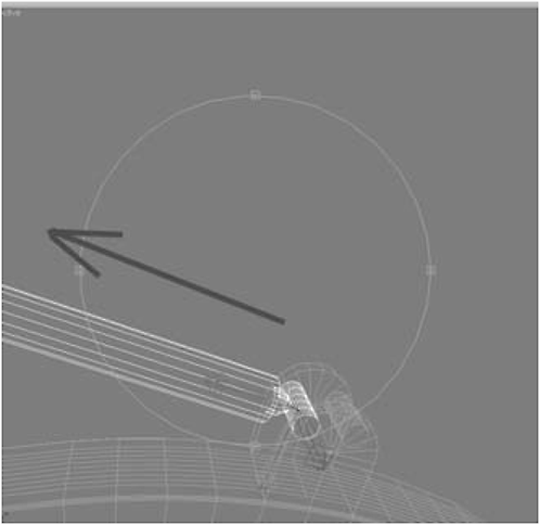
Figure 1-464
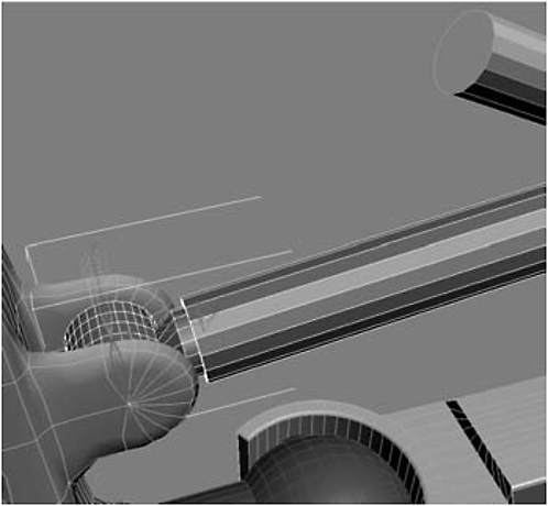
Figure 1-465
Urgent: This is a crucial step. In order for the hydraulics to work right, the pivots for the piston and the shaft have to be aligned.
43. Select the piston. On the Create panel, click the Motion icon (it looks like a wheel). Click the plus sign next to Assign Controller, select Rotation: Euler XYZ, and then click the Assign Controller button (which has a question mark for an icon).
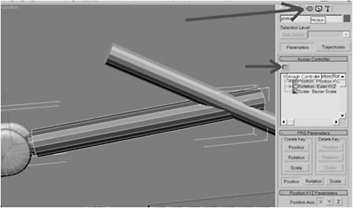
Figure 1-466
FYI: Animation in Max is handled by controllers. Controllers store and interpolate animation values. For our purposes, we’ll be using a “LookAt” controller. A LookAt controller makes sure that whatever is assigned to it is always aligned with (looking at) a target. For example, the most common use of a LookAt controller is to make sure an animated character ’s eyes are looking at a target object. For each eye, you would assign a LookAt controller and link it to a target object the eyes are supposed to follow. In our case, we’ll assign a LookAt controller to the piston and link it to the shaft’s pivot point. That way, when the shaft moves, the piston will follow.
44. Select LookAt Constraint from the Assign Rotation Controller list. In the LookAt Constraint rollout, click the Add LookAt Target button and then pick shaft from the Pick Object list.

Figure 1-467

Figure 1-468
45. Under Select LookAt Axis, select X; this will be the axis that the piston will align to and is the reason I had you make sure the pivots for the piston and the shaft were facing each other.

Figure 1-469
Fire Drill: So why is the piston turned? I deliberately did not tell you to make sure that not only the X pivots were facing each other, but that the Z axes had to be aligned in the same direction. Look back at Figures 1-464 and 1-465 and examine them closely. In 1-464, the shaft’s pivot Y axis is pointing down, while its Z axis is pointing toward the front. In 1-465, however, the piston’s pivot Z axis is pointing down and the Y axis is pointing back. This explains why, once we add the LookAt constraint, the piston rotates 90 degrees. The LookAt constraint is working perfectly, ensuring that the X axes are aligned. But to do so required Max to rotate the shaft. Fortunately, this is easily fixed by rotating the piston’s pivot to align its Z axis with that of the shaft’s pivot.
46. Select Affect Pivot Only and use the Rotate tool to rotate the piston’s pivot until it is aligned.

Figure 1-470
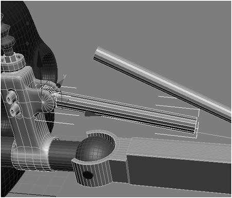
Figure 1-471
FYI: Notice a thin blue line in Figure 1-470. That indicates the linkage of the LookAt controller to its target.
Fire Drill: At this point, we’re going to run into some difficulty when we try to assign a LookAt controller to the shaft, with the piston’s pivot as a target. Because we’ve already constrained the piston’s pivot to “look at” the shaft’s pivot, Max won’t let us use the piston’s pivot as a target for a LookAt constraint assigned to the shaft. To get around this, we’ll use a dummy, linked to the shaft, as a target.
A dummy is a non-rendering object that is designed for situations just like this. It’s simply a non-rendering object.
47. Under the Create panel, click the Helper button (looks like a tape measure), click the Dummy button, and create a Dummy object between the stanchions on the hydraulic pump. Select and Link the dummy to the piston and Link the piston to the hydraulic pump.
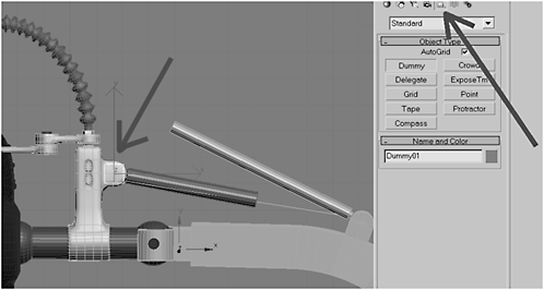
Figure 1-472

Figure 1-473
48. Select and Link the shaft to the middle leg (not shown). Select the shaft and click the Motion tab (the fourth tab on the Create panel). In the Assign Controller rollout, select Rotation: Euler XYZ and click the Assign button (it has a question mark icon). A bunch of new rollouts will appear. Click Add LookAt Target and pick Dummy01 from the list.
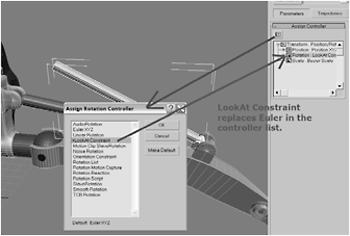
Figure 1-474

Figure 1-475
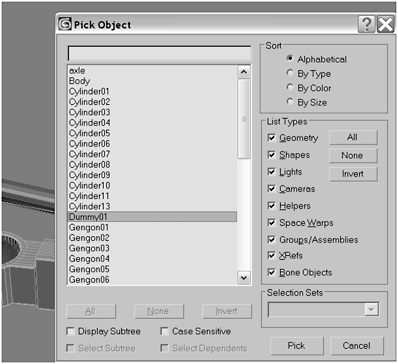
Figure 1-476
49. Align the dummy’s pivots to coincide with the shaft’s (the blue line from this constraint should converge with that of the previous constraint). Then select the tip of the shaft and scale it to comfortably fit within the piston.

Figure 1-477
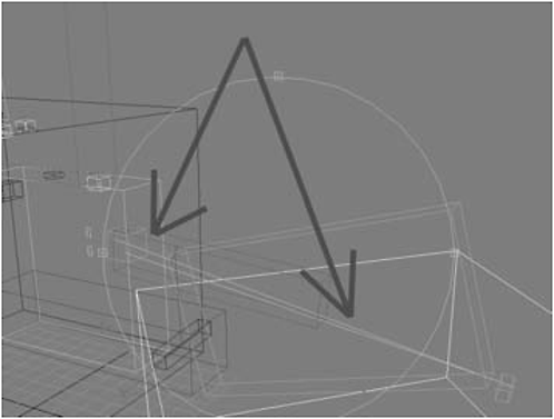
Figure 1-478
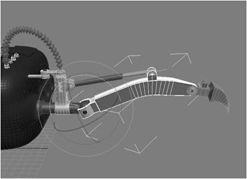
Figure 1-479: Now, when you move the middle leg, the shaft will move in and out of the piston the way a normal piston would work.
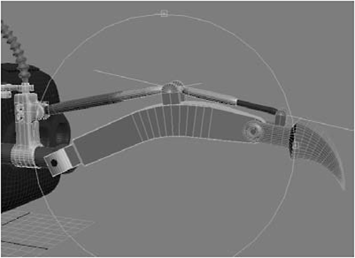
Figure 1-480: Now, when you move the middle leg, both pistons should work.
51. Create a Cylinder on top of the first piston (the one attached to the hydraulic pump), about three-fourths of the way down the shaft. Convert it to an Editable Polygon and delete the bottom-facing polygon.

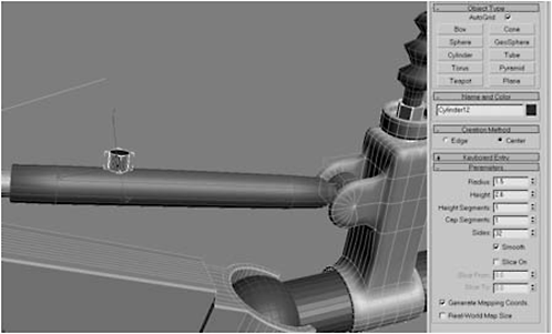
Figure 1-481
52. Select the piston, click Attach List, and attach the cylinder you just created.
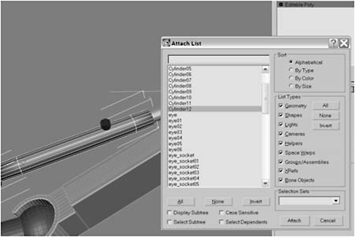
Figure 1-482
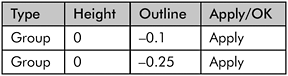
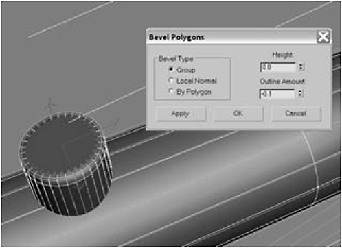
Figure 1-483

Figure 1-484
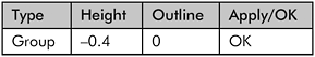

Figure 1-485
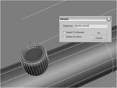
Figure 1-486
55. Repeat steps 51-54 to create a mount on the claw piston, on the outside facing front. Call it piston_mount02.
56. Create a Hose like the one in Figure 1-487.
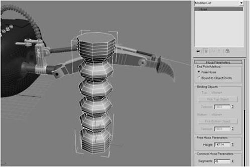
Figure 1-487
Don’t Forget: I promised you in the FYI box at the end of the last section that we would use the polygons we detached from the hydraulic pump and called hydraulic_anchor. Well … that time is now.
57. Switch the hose from Free to Bound to Object Pivots. Click Pick Top Object, hit H, and select hydraulic_anchor from the list. Then click Pick Bottom Object, hitH, and select piston_mount.

Figure 1-488

Figure 1-489
58. Select hydraulic_anchor and piston_mount and center their pivots by choosing Center to Object. Set the Top Tension to 83, the Bottom Tension to 20, the Segments to 70, the Diameter to 1.5,and the Sides to 16.

Figure 1-490
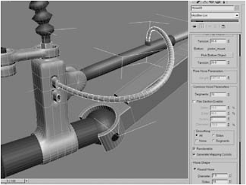
Figure 1-491
59. Repeat steps 56-58 to create a hose connecting hydraulic_anchor02 to piston_mount02.
Figure 1-492
60. Select the polygons shown in Figure 1-493.
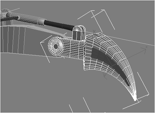
Figure 1-493

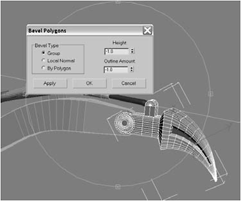
Figure 1-494
62. Select the polygons on the top of the claw as shown in Figure 1-495.
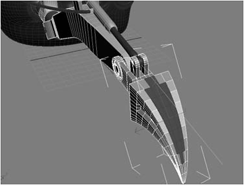
Figure 1-495

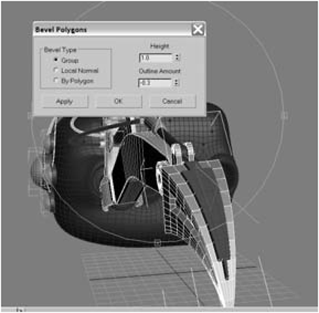
Figure 1-496

Figure 1-497
64. Select the 11 polygons shown in Figure 1-498 on both the front and back sides of the middle leg.

Figure 1-498
65. Click Bevel Settings:
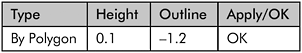

Figure 1-499

Figure 1-500
67. Add a Smooth modifier to the upper leg’s stack and then collapse the stack.
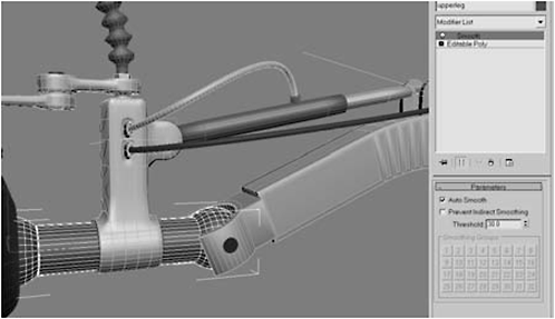
Figure 1-501
Day 7: Creating the Remaining Legs
1. Select the components making up the leg as shown below.

Figure 1-502

Figure 1-503

Figure 1-504

Figure 1-505
Fire Drill: You can see from Figure 1-505 that constrained objects get — what’s the technical term? — seriously jacked up when you clone them. Max does not automatically update constraints when you create a clone. So … you have to select each constrained clone and update its constraint target to the new target.
3. Select a cloned hose, open the Modify panel, and assign its binding object to cloned versions.

Figure 1-506

Figure 1-507
4. Reattach the hoses to their cloned binding objects and check that the pistons’ and shafts’ LookAt constraints are attached to the right objects. Make sure the legs and claw are still linked together.
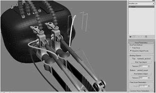
Figure 1-508
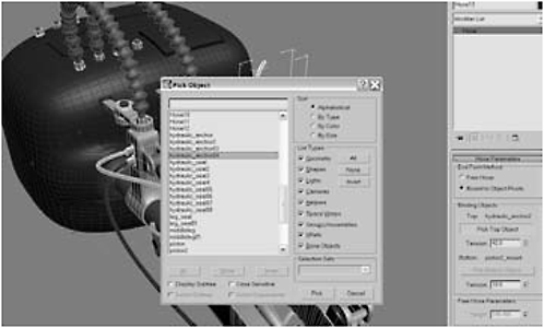
Figure 1-509
5. Select all the leg elements again and clone them into the next socket. Reconnect all the bindings and constraints, and then clone a leg into the last socket.
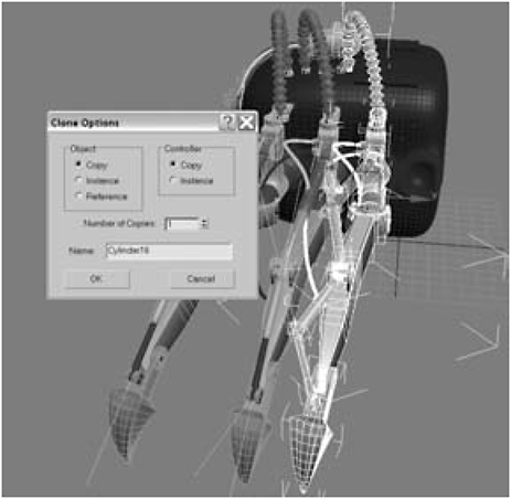
Figure 1-510

Figure 1-511
FYI: At this point, we’d normally mirror clone the objects and be done. However, Max has other ideas. Not only do you get the same problem with linkages, but the hoses inexplicably get turned inside out. Rather than fixing them, it’s easier just to make new ones.
6. Select all the front leg’s elements, except the hoses, and clone them into the first socket on the left side. Reconnect all the bindings and constraints, and then create new hoses. Select the front left leg and clone it to create the remaining left legs.
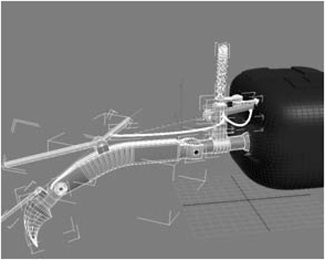
Figure 1-512
Figure 1-513
7. When you’ve added all the legs, hit F9 to do a render and you’re done!

Figure 1-514
Why Doesn’t My Model Look Real?
One of the first things you need to understand about 3D modeling — guess I should’ve mentioned this first, huh? — is that your finished product, no matter how good the model, is going to look like crap. Or … in this case, a child’s toy rather than a menacing purveyor of carnage. The reason? Materials.
You ever see a 1970 Hemi ’Cuda without its paint job? Pretty unimpressive. Okay, a 1970 Hemi ’Cuda is pretty impressive with or without paint. But you see my point: Materials make all the difference in the world. If you want to learn how to slap a nifty paint job on your spider bot, check out the three materials videos on the companion DVD.

This is the hunter-killer bot we create in Chapter 2, complete with texture and lighting.