

Adapting a Concept
To start off with, we will try to keep the brief as ‘real’ as possible – by changing it right from the beginning. The concept we have been given is for one of the inventions of Robert’s father. It is a gadget that uses a prism to split the different spectra of colors in light to make the plant’s leaves contain all the colors of the rainbow.
This was originally designed as one of the inventions for an interior scene; but as our scene will be outdoors, we will adapt this concept and scale it up so that we see it nice and big in our final render.
We will keep the gadget the same, but we’ll swap out the potted plant for a palm tree so that it is more visible in our scene.
We could do a sketch for this, but in this case, I’m confident that I know what I want to do; so, we’ll just get started with the modeling.
We will build the models separately, first the palm tree; and then the gadget, using a variety of techniques.
Before any modeling can begin, we need to gather a selection of palm tree references. This is standard practice for any professional artist when starting any new modeling task. Once we have a good selection, we will pick the best two or three pictures to use as our points of reference. The criteria we’re looking for in our key images are form, color, and texture. Don’t forget the palm fronds will need texture reference too!
Don’t fall into the trap of modeling what you think the tree looks like – a lot of artists do this and generally produce poor-looking models. Always get references and always look at them.
For this chapter, we will customize our modifier set. The modifier set is a group of buttons that you can customize to display your favorite modifiers and make them easily accessible. Modifier-set usage and setup differs from artist to artist, depending on their role or experience; but specialized sets can and should be used by modelers, animators, texture artists, and even designers. These are the tools you will keep coming back to; so any modifiers you use a lot should go here – it will save you a lot of time in the long run.
To begin with, bring up the Configure Modifier Sets dialogue box by clicking the button.
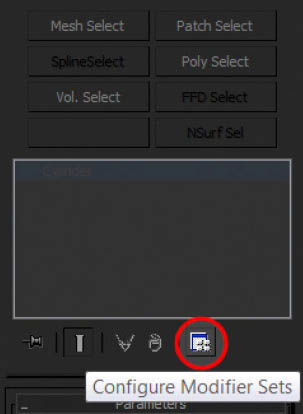
FIG 3.1
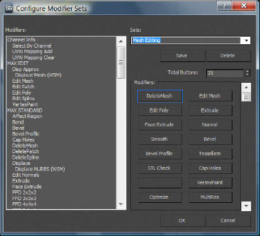
FIG 3.2
Here, we can customize our modifier set from a list of modifiers (on the left) and assign them to the buttons on the right. We’ll start off with a default set and then customize it.
Open the Sets rollout and choose Mesh Editing (see Fig. 3.2). This will provide a set with 21 buttons.
Next, we customize the set. First, in the Total Buttons rollout, change the number from 21 to 10. Notice the name has now disappeared under the Sets header to reflect the fact that the set has been customized. Next, we need to swap out the modifiers we don’t want for the ones we want.
Left click, hold, and drag on the DeleteMesh button and (while holding) move over to the Modifiers window and release. The button will now appear blank. Repeat this procedure for all the buttons except Edit Poly and Edit Mesh.
Once this has been done, scroll the modifier menu and drag into the empty slots the following functions; FFD 2x2x2, Bend, Twist, UVW Map, Unwrap UVW, CrossSection, Surface, and Edit Spline.
The layout can be rearranged however you like (see Fig. 3.4). Under the Sets header, type in the name for the new set ‘Chapter 3.’ Additional buttons can be added (they will appear blank until a function is dragged onto it) at any time, but be aware that the name will disappear once a customization has taken place. If you change them, remember to save them.
Once the button layout is finalized, click Save and OK to close the dialogue box.
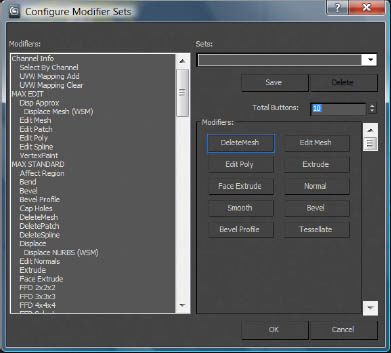
FIG 3.3
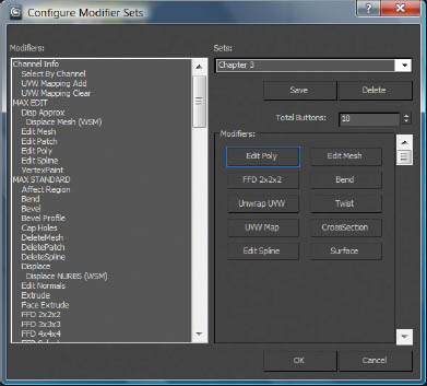
FIG 3.4
Now create two reference or block-out objects as rough estimates of scale and color for the two objects. The machine reference object should be approximately 250 cm and the palm should be approximately 700 cm. Create three basic materials and colors, as shown in Fig. 3.5. After completion, name the objects as Machine ref, Palm ref, and Fronds ref; and hide them.
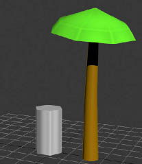
FIG 3.5
The first model we create will be the palm tree. First we will make the trunk. Before we build the model, we will create the texture map in Photoshop.
As the model will be based around a cylinder, the UV mapping will be cylindrical. Knowing this beforehand affects how we look at texture creation and a little forethought and planning will yield better results.
Mirroring the aspect of the target, the texture will be taller than it is wide. So, with this in mind, create a texture with the dimensions of 1024 pixels tall and 128 pixels wide.
Always create textures at double the size (or resolution) you ultimately need, as Photoshop filters work more efficiently at a high resolution. After the texture is complete, reduce the size by 50% (Image > Size). This is typical industry practice. Another trick is to save the original large texture as a source image that you can apply to your models for portfolio renders. They need to be small and efficient for in game, but can be bigger (and therefore, look better) for your portfolio renders.
The palm texture will be made up of three different segments (as shown in Fig. 3.7). These will be the main body (1), the top (2) and the falloff/roots (3). If you can get all the elements from one reference image, then great; but if not, find up to three images (one for each area).
Layer each part on top of the base (1) and fade them off to make a smooth blend using the layer-mask function. A simple vertical gradient mask should give the desired falloff effect.
FIG 3.6
![]()
FIG 3.7
![]()
FIG 3.8
Once this is done, flatten the image. Next, using Filter > Other > Offset command, offset the texture in the horizontal plane by 64 pixels. The texture has now wrapped round, revealing any breaks in tiling down the central spine of the texture. Repair this effect using the Heal and Clone tools. With this completed, you can offset the texture again and you should have something resembling Fig. 3.8.
With the texture ready, we can move back to Max and begin construction of the trunk model. Start by creating a cylindrical primitive object roughly the same scale as the reference object. The starting dimensions should be: radius 75 cm, height 700 cm, and segments 10. The trunk will have varying segment widths, so the radius denotes the absolute maximum. Once this is created, add an Edit Mesh modifier and select the central vertex on the top set of polygons. Pull this up a little to match Fig. 3.9.
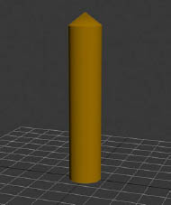
FIG 3.9
Finally, go into polygon mode (4 on the keyboard), select all of the polygons (CTRL + A) and set the Material ID to 1.
The model is now prepared for UV mapping. Add a UVW Map modifier to the stack and select cylindrical as the mapping type. Click the Fit button and the gizmo should match the dimensions of the model (Fig. 3.10). If the gizmo is horizontal, just rotate it so that it points upward, then use the fit function.
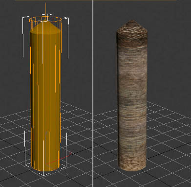
FIG 3.10
The default coordinates are fine for this model, so they don’t need to be changed. Create a Multi-Sub Object material and change the number of IDs to two. Slot 1 will be for the tree trunk material and Slot 2 will be for the leaves. Name them Trunk and Palm, respectively. Next, just load the texture map for the trunk in the diffuse texture slot and click the Assign Material to Selection button.
Next, checking back against your reference photos and using your reference object an average, add an Edit Mesh modifier and adjust the segment scale of the model to make the form more organic, like a real tree trunk. This can be further embellished by rotating the segments too. When you think the model is starting to match the reference, add some subtle modifiers such as Twist and Bend. Experiment with the values until you are happy with the results. Name the model Trunk.
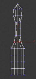
FIG 3.11a
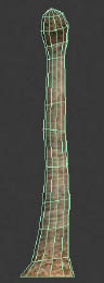
FIG 3.11b
With the trunk complete, we can now move onto the palm leaves. Create a plane with the following dimensions; 375 cm height, 150 cm width, Length Segments 6 and Width Segments 4. This is the basis for the palm leaf object.
Go into Photoshop and create a palm leaf texture from one your reference images (or find some additional images for this). Once you have chosen a key image, create an alpha map and save it. Name the frond texture Palm_Frond and the alpha texture Palm_Frond_Alpha.
Put these two textures in the second ID slot of the Multi-Sub Object material. They should occupy the diffuse and opacity slots, respectively. Call the material “Palm” if you haven’t named it already. Apply the material to the plane, add an Edit Mesh to the stack, select all the polygons and change the material ID to 2. The palm leaf texture should appear on the leaf model.
Next, add a Bend modifier to the stack. Select X as the bend axis and set the angle to 90°. The result should match Fig. 3.12. The frond object can now be used to populate the trunk.
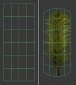
FIG 3.12
Move the frond object to the top section of the palm trunk. Again, referring to your reference object, duplicate the frond around the circumference of the top of the trunk, varying the scale and rotation to stop the population looking mechanical. When a density similar to the reference is achieved, group the objects and the trunk together. Name the group Palm tree.
Additional form changes such as twists and bends can be applied to the group if need be.
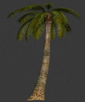
FIG 3.13
With the palm complete, we can now move onto the gadget or invention.
First, we need to make the main hub. This can be done with a simple Lathe operation. To begin with, using the spline tools, create a cross section of the main hub. Once this is finished, choose Lathe from the drop-down modifier menu and set the segments to 16. The before and after versions of this process can be seen in Fig. 3.14a.
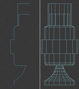
FIG 3.14a
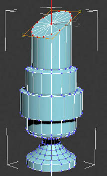
FIG 3.14b
Add an Edit Mesh modifier and set up the smoothing groups for the model. An auto smooth set to the default angle of 45° will be fine.
To create the tilt on the central cylinder (what will become the glass section later), select the top vertices and add an FFD 2x2xv2 modifier. An orange gizmo will appear around the selected vertices.
Go into the Sub Object mode Points and from the top view, select the bottom points. To prevent de-selection, lock the selection using the Selection Lock Toggle button.
Returning to a perspective view, pull the selected points down, as shown in Fig. 3.14b.
The main body of the model is complete and now needs to be split up into its separate components and texture-mapped. Select polygon groups by type (horizontal, cylindrical, etc.). Be sure to also separate by target material type (metal, glass, and liquid).
Using this logic, I separated the model into seven unique parts (Fig. 3.15).
Now, the model has been split up for mapping purposes, we can re-attach by material type, which will reduce the number of materials down to three – Metal, Glass, and Liquid. As long as the model isn’t welded, there will still be separate parts/elements, making it easy to quickly select and texture-map it.
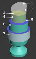
FIG 3.15
Once this has been done, map each object. Using the metal base as an example, add an Edit Mesh.
Choose Element as a sub-selection and ctrl click each element that will use vertically aligned mapping. Again, as the model is cylindrical, we use cylindrical mapping. If the gizmo appears rotated, alter until you are happy with the alignment and use the Fit command.
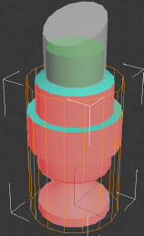
FIG 3.16a
Next, add an Unwrap UVW modifier and select the button labeled Open the UV editor. Once open, turn off the checker pattern. You can now see the UVs you have just applied laid out in wireframe.
Using the tools provided in the upper left corner of the editor window (Move, Rotate, Scale, Freeform, etc.), scale down the UVs to resemble Fig. 3.16b.
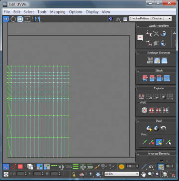
FIG 3.16b
Now, move the UVs outside of the center square (they will be repositioned later, so it doesn’t really matter where you move them to as long as the area is empty). Now, select the horizontal elements and map those with a Planar gizmo. This time, add an Edit Mesh and do not sub-select. Now, add the Unwrap modifier. Notice now, the whole object is shown as you didn’t limit the selection.
Scale the new UVs down and move the previous set into the square (as shown in Fig. 3.16c).
We now have the basis for the texture page for this model. This process now needs to be repeated with the remaining two parts. After this is completed, they can be reattached to the ‘metal’ part of the model. After this has been done, add an Unwrap modifier. The resulting view will show overlapping UV sets in the same window. This needs to be tidied up before we continue.
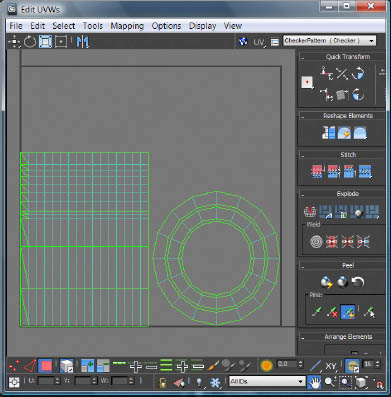
FIG 3.16c
Check the Select by Element UV toggle and rescale and position the UVs using Freeform Mode (Fig. 3.16d). Be sure to leave some space for the remaining parts of the model which are yet to be constructed (Fig. 3.16e).
The final parts of the model to be built are the handles, the prism, the lens, and the arm.
These can all be made from primitives. As you create the parts, reference the sketch for scale and rotation.
The Prism is basically half a cuboid. We can use Box mapping or Planar mapping for this.
The Lens is basically a cylinder with additional cap segments. Scale these in and extrude to model the glass part of the lens.
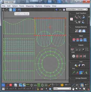
FIG 3.16d
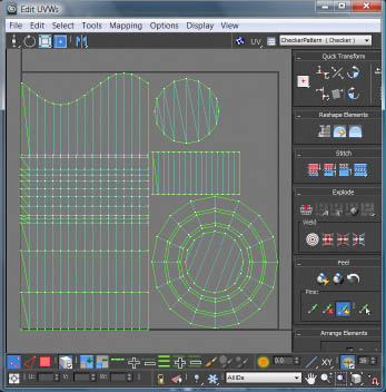
FIG 3.16e
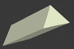
FIG 3.17a
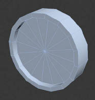
FIG 3.17b
Use Cylindrical mapping for the rim and Planar mapping for the glass and edges.
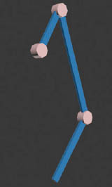
FIG 3.17c
For the Arm, use simple boxes and cylinders. Model and map one of each of the cylinders and arm components, then copy them to make additional joints. Attach together when complete.
Create the Handles by starting with a Cylinder and scaling it along the Y axis to flatten the shape. Provide enough segments to extrude out the middle area and then bend the top and bottom parts. Use an FFD modifier to pull in the top points, creating a vertical slant. The two connected base parts are simple cylinders – create one, map it and then copy it for the other one. When complete, Rotate around the main object at 60-degree intervals, then attach together.
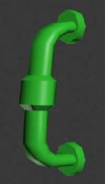
FIG 3.17d
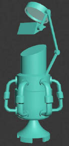
FIG 3.17e
After editing the base of the core object to properly match the concept, all the remaining parts can be attached to the main model. The UVs will need tidying up and may require a little rearrangement.
This will provide us with everything we need to make the texture. Using Tools > Render UVW Template, render out the UVs as a TGA image. This forms the basis of the texture page.
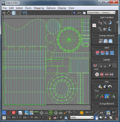
FIG 3.17f
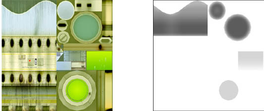
FIG 3.18a
Using the UV render as a layout, create diffuse and opacity (alpha) maps. The opacity map is needed for the glass areas. Place the textures into the relevant slots in the Material Editor and apply them to the model.
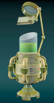
FIG 3.18b
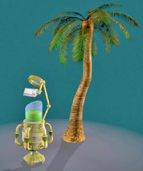
FIG 3.18c
Set up a basic rig and render the model to check the results. Edit the diffuse and opacity maps until you are happy with the results; also make sure the material is two-sided or the glass will look too transparent.
Note
As a finishing touch, try offsetting the top/cap vertices for the ‘liquid’ element in the Y axis (as shown in the render image Fig. 3.18b); this will help give the sensation of a liquid.