
CHAPTER 1
Introduction to the Arduino
IN THIS CHAPTER I INTRODUCE YOU to the Arduino. I first give a brief explanation of what the Arduino is. I then specifically concentrate on the Arduino Mega 2560. I discuss the general features of the Arduino Mega 2560 including the capabilities and key functional components of the device. Next, I give a quick summary of languages that the Arduino uses which are C and C++. Next, I discuss the Arduino Integrated Development Environment (IDE) software that is needed to develop programs for the Arduino. I cover each key function of the Arduino IDE and then conclude with a hands-on example where I give detailed step-by-step instructions on how to set up the Arduino for development and how to run an example program using the Arduino IDE.
What Is an Arduino?
The Arduino is an open-source microcontroller that uses the C and C++ languages to control digital and analog outputs to devices and electronics components and to read in digital and analog inputs from other devices and electronics components for processing. For example, the Arduino can read in information from a sensor to a home security system that would detect the heat that a human being emits and sends a signal to the Arduino to indicate that a human is in front of the sensor. After receiving this information the Arduino can send commands to a camera to start taking pictures of the intruder or intruders and save these images to an SD card for later viewing. It can also transmit a message over Wi-Fi to an Android cell phone so that a text alarm notification message is sent to the homeowner. The official web site of the Arduino is http://www.arduino.cc.
Why the Arduino Mega 2560?
There are many different Arduino models out there. However, in order to perform the examples in this book you will need an Arduino Mega 2560. The reason for this is that the Arduino Mega 2560 has many hardware serial ports that can communicate at high speed with the ESP-01 ESP8266 module that will be responsible for Wi-Fi communication. The Arduino UNO only has one hardware serial port that is already used for debugging with the Arduino IDE’s serial monitor. A separate software serial port can be created on the Arduino UNO but it is unreliable at high speeds with many people reporting that any speed above 9600 baud is unreliable. Most of the recent ESP-01 modules being produced now are set to the default speed of 115,200 baud. Another consideration is the large amount of current that the ESP-01 module can draw. The ESP-01 module can draw up to 170 mA when operating under normal circumstances. If you add in the current drawn by other components attached to the Arduino, such as sensors, then the total might quickly add up to the maximum current allowed for the Arduino UNO which is around 400 mA. However, for the Arduino Mega 2560 the maximum allowed current is 800 mA which is considerably more. Also, please note that these maximum currents should not be sustained for long periods of time otherwise there could be damage to the Arduino board. This information comes from the official Arduino web site at https://playground.arduino.cc/Main/ArduinoPinCurrentLimitations.
The Arduino Mega 2560 Specifications
![]() Microcontroller: ATmega2560
Microcontroller: ATmega2560
![]() Operating voltage: 5 V
Operating voltage: 5 V
![]() Input voltage (recommended): 7 to 12 V
Input voltage (recommended): 7 to 12 V
![]() Input voltage (limit): 6 to 20 V
Input voltage (limit): 6 to 20 V
![]() Digital I/O pins: 54 (of which 15 provide PWM output)
Digital I/O pins: 54 (of which 15 provide PWM output)
![]() Logic level: 5 V is true or high
Logic level: 5 V is true or high
![]() Analog input pins: 16
Analog input pins: 16
![]() DC current per I/O pin: 20 mA
DC current per I/O pin: 20 mA
![]() DC current for 3.3 V pin: 50 mA
DC current for 3.3 V pin: 50 mA
![]() Total maximum current: 800 mA
Total maximum current: 800 mA
![]() Total maximum current (USB powered): 500 mA (>500 mA will trip the Arduino’s fuse)
Total maximum current (USB powered): 500 mA (>500 mA will trip the Arduino’s fuse)
![]() Flash memory: 256 kB of which 8 kB used by bootloader
Flash memory: 256 kB of which 8 kB used by bootloader
![]() SRAM: 8 kB
SRAM: 8 kB
![]() EEPROM: 4 kB
EEPROM: 4 kB
![]() Clock speed: 16 MHz
Clock speed: 16 MHz
![]() LED_BUILTIN: 13
LED_BUILTIN: 13
![]() Length: 101.52 mm
Length: 101.52 mm
![]() Width: 53.3 mm
Width: 53.3 mm
![]() Weight: 37 g
Weight: 37 g
The Official Arduino Mega 2560
I purchased an official Arduino Mega 2560 from the official Arduino web site that was listed earlier for about $40.00 and the unit arrived in early October 2018. Included in the package was a new Arduino 2560 microcontroller, a thank you note, a sheet of stickers, and a plastic stand that was attached to the bottom of the Arduino. See Figure 1-1.
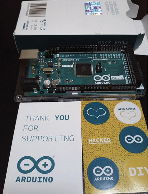
Figure 1-1 Contents of the official Arduino Mega 2560 that I purchased.
The backside of the Arduino 2560 is shown in Figure 1-2.
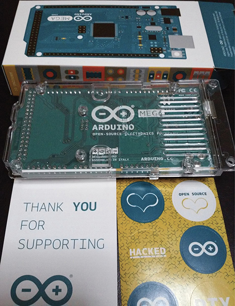
Figure 1-2 Backside of the Arduino Mega 2560.
Since the Arduino Mega 2560 is an open-source hardware, anyone can make and sell their own Arduino Mega 2560 board legally as long as they don’t use certain logos that are trademarked. Thus, there are many unofficial Arduino Mega 2560 boards available on sites such as Amazon that are a fraction of the cost of an official Arduino. For example, on Amazon I just searched for an Arduino Mega 2560 and the search results returned many unofficial boards which cost around $15.00 USD each. This is less than half the price of an official Arduino Mega 2560 bought from the official Arduino store.
Arduino Mega 2560 Components
This section covers the functional components of the Arduino Mega 2560.
USB Connection Port
The Arduino Mega 2560 has a USB connector that is used to connect the Arduino to the main computer development system via standard USB A male to B male cable so it can be programmed and debugged. See Figure 1-3.

Figure 1-3 The USB port on the Arduino Mega 2560.
9-V Battery Connector
The Arduino Mega 2560 has a 9-V battery connector where you can attach a 9-V battery to power the Arduino. See Figure 1-4.

Figure 1-4 The 9-V battery connector for the Arduino Mega 2560.
Reset Button
There is a Reset button on the Arduino Mega 2560 where you can press the button down to reset the board. This restarts the program contained in the Arduino’s memory. See Figure 1-5.
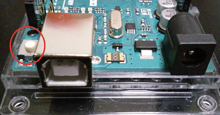
Figure 1-5 The Reset button on the Arduino Mega 2560.
Digital Pulse Width Modulation (PWM)
The Arduino Mega has many digital pins capable of simulating analog output through the process of PWM. For example, a light-emitting diode (LED) light generally has only two modes which are on (full brightness) and off (no light emitted). However, with digital PWM the LED light can appear to have a brightness in between on and off. For instance, with PWM an LED can start from an off state and slowly brighten until it is at its highest brightness level and then slowly dim until back to the off state. The digital pins on the Arduino Mega 2560 that support PWM are pins 2 through 13. These PWM capable digital pins are circled in Figure 1-6.
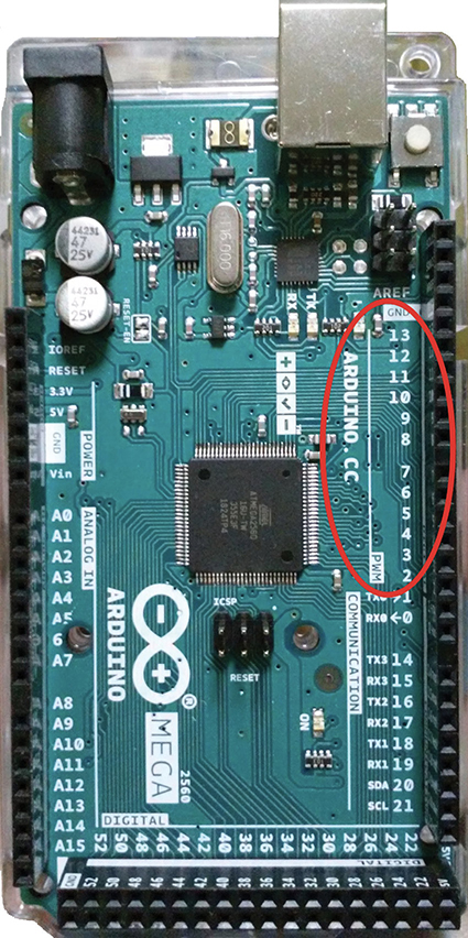
Figure 1-6 Pins capable of pulse width modulation.
Communication
The communication section of the Arduino Mega 2560 contains pins for serial communication between the Arduino and another device such as a Wi-Fi adapter like the ESP-01 module or your personal computer. The Tx0 and the Rx0 pins are connected to the USB port and serve as communication from your Arduino to your computer through your USB cable. The Serial Monitor that can be used for sending data to the Arduino and reading data from the Arduino uses the Tx0 and Rx0 pins. Thus, you should not connect anything to these pins if you want to use the Serial Monitor to debug your Arduino programs or to receive user input. I will talk more about the Serial Monitor later in this book. In addition, the Arduino Mega 2560 has three more sets of serial communication pins that are labeled Tx1/Rx1, Tx2/Rx2, and Tx3/Rx3. See Figure 1-7.

Figure 1-7 Hardware serial communication pins.
The I2C Interface
The I2C interface is a communications interface that consists of an SDA pin which is pin 20 and is used for data and an SCL pin which is pin 21 and is used for clocking or driving the device or devices attached to the I2C interface. The SDA and SCL pins are circled in Figure 1-8.

Figure 1-8 The I2C interface.
Digital Output/Input
The Arduino Mega 2560 has many more digital output/input pins than the Arduino Uno which is a popular Arduino model for beginners with a limited number of digital and analog output/input pins. Pins 22 through 53 are digital pins on the Arduino Mega 2560. Pins discussed earlier that are capable of PWM are also capable of normal digital output/input. See Figure 1-9.

Figure 1-9 The Arduino Mega 2560 has many digital pins.
Analog Input
The Arduino Mega 2560 has 16 analog input pins that can read in a range of values instead of just digital values of 0 or 1. The analog input pin uses a 10 bit analog to digital converter to transform voltage input in the range of 0 to 5 V into a number in the range between 0 and 1023. See Figure 1-10.

Figure 1-10 Analog input pins.
Power
The Arduino Mega 2560 has outputs for 3.3 and 5 V. One section that provides power is located on the side of the Arduino. Another section is on the bottom of the Arduino which has two 5-V power pins available for use. There is a total of one 3.3-V power pin and three 5-V power pins on the Arduino Mega 2560 that you can use to power your electronics circuit. You can also provide your own power source by connecting the positive terminal of the power source to the Vin pin and the ground of the power source to the Arduino’s ground. Make sure the voltage being supplied is within the Arduino board’s voltage range. See Figure 1-11.
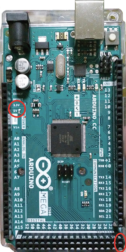
Figure 1-11 Power pins on the Arduino Mega 2560.
Ground Pins
There are 5 ground pins on the Arduino Mega 2560 and are circled in Figure 1-12.

Figure 1-12 The ground pins on the Arduino Mega 2560.
The Custom Fuse
The most unique component of the Arduino Mega 2560 is the golden resettable fuse with the Arduino infinity logo on it. It is located between the USB port and the 9-V battery power input jack. This fuse is tripped if the Arduino uses more than 500 mA of current when being powered through the USB port. See Figure 1-13.
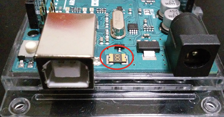
Figure 1-13 The custom Arduino fuse.
Overview of the C/C++ Language for the Arduino
The Arduino uses C and C++ in its programs, which are called sketches. This section briefly summarizes key language elements. This is not meant as a reference guide, and ideally, you should have some experience with a programming language similar to C and/or C++.
Comments
//. This signifies a single-line comment that is used by the programmer to document the code. These comments are not executed by the Arduino.
/* */. These enclose a multiline comment that is used by the programmer to document the code. These comments are not executed by the Arduino.
Data Types
![]()
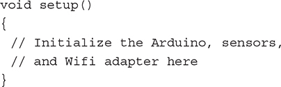
void. This type being used with a function indicates that the function will not return any value to the function caller. For example, the setup() function that is part of the standard Arduino code framework has a return type of void.
![]()
boolean. A boolean variable can hold either the value of true or false and is 1 byte in length. For example, in the following code, the variable result is declared of type boolean and is initialized to false:
boolean result = false;
![]()
char. The char variable type can store character values and is 1 byte in length. The following code declares that tempchar is of type char and is an array with 50 elements:
char tempchar[50];
![]()
unsigned char. The unsigned char data type holds 1 byte of information in the range of 0 through 255.
![]()
byte. The byte data type is the same as the unsigned char data type. The following code declares a variable called data of type byte that is initialized to 0:
byte data = 0;
![]()
int. The int data type holds a 2-byte number in the range of −32,768 to 32,767.
![]()
unsigned int. This data type is 2 bytes in length and holds a value from 0 to 65,535.
![]()
word. This data type is the same as the unsigned int type.
![]()
long. This data type is 4 bytes in length and holds a value from −2,147,483,648 to 2,147,483,647.
![]()
unsigned long. This data type is 4 bytes in length and holds a value between 0 and 4,294,967,295.
![]()
float. This is a floating-point number that is 4 bytes in length and holds a value between −3.4028235E+38 and 3.4028235E+38.
![]()
double. On the current Arduino implementation, double is the same as float with no gain in precision.
![]()
String. This is a class object that allows the user to easily manipulate groups of characters. In the following code, a new variable called ssid, which represents the name of an access point, is given the name of ESP-01.
String ssid = "ESP-01";
![]() array. An array is a continuous collection of data that can be accessed by an index number. Arrays are 0 based, so the first element in the array has an index of 0. Common types of arrays are character arrays and integer arrays. The following code creates an array of
array. An array is a continuous collection of data that can be accessed by an index number. Arrays are 0 based, so the first element in the array has an index of 0. Common types of arrays are character arrays and integer arrays. The following code creates an array of ClientInfo class objects called Clients. The number of elements in the array is held in the constant integer variable MAX_CLIENTS which is set to 4.
const int MAX_CLIENTS = 4;
ClientInfo Clients[MAX_CLIENTS];
Constants
![]()
INPUT. This is an Arduino pin configuration that sets the pin as an input pin that allows you to easily read the voltage value at that pin with respect to ground on the Arduino. For example, the following code sets the pin defined as VSYNC on the Arduino as an INPUT pin, which allows you to read the voltage value of the pin. The function pinMode() is an Arduino function included in the built-in library.
pinMode(VSYNC, INPUT);
![]()
OUTPUT. This is an Arduino pin configuration that sets the pin as an output pin that allows you to drive other electronics components such as an LED or to provide digital input to other devices in terms of HIGH or LOW voltages. In the following code, the pin that is defined as WEN is set to OUTPUT using the built-in pinMode() function:
pinMode(WEN , OUTPUT);
![]()
HIGH (pin declared as INPUT). If a pin on the Arduino is declared as an INPUT, then when the digitalRead() function is called to read the value at that pin, a HIGH value would indicate a value of 3 V or more at that pin.
![]()
HIGH (pin declared as OUTPUT). If a pin on the Arduino is declared as an OUTPUT, then when the pin is set to HIGH with the digitalWrite() function, the pin’s value is 5 V.
![]()
LOW (pin declared as INPUT). If a pin on the Arduino is declared as an INPUT, then when the digitalRead() function is called to read the value at that pin, a LOW value would indicate a value of 2 V or less.
![]()
LOW (pin declared as OUTPUT)OUTPUT, then when the digitalWrite() function is called to set the pin to LOW, the voltage value at that pin would be set to 0 V.
![]()
true.
![]()
false.
The define Statement
The define statement assigns a name to a constant value. During the compilation process, the compiler will replace the constant name with the constant value:
#define constantName value
The following code defines the software serial data receive pin as pin 6 on the Arduino and the software serial data transmit pin as pin 7 on the Arduino:
#define RxD 6
#define TxD 7
These definitions are used in defining which pins are to receive and transmit data via the software serial method, which is initialized as follows and can be used to communicate with a Wi-Fi adapter:
SoftwareSerial WifiAdapter(RxD,TxD);
Note: For this book I recommend using hardware serial ports rather than software serial ports because software serial ports are unreliable at high speeds with some users reporting that any speed over 9600 baud generates many errors in transmission. I also personally tried to use software serial at a high baud rate to communicate with the ESP-01 Wi-Fi module (115,200 baud) and the results were unreliable and unusable.
The include Statement
The #include statement brings in code from outside files and “includes” it in your Arduino sketch. Generally, a header or .h file is included that allows access to the functions and classes inside that file. For example, we can include in a program a Wire.h file, which lets us use the Wire library. The Wire library has functions to initialize, to read data from, and to write data to a device connected to the I2C interface. We need the Wire library to use a device that uses the I2C bus.
#include <Wire.h>
The Semicolon
Each statement in C/C++ needs to end with a semicolon. For example, when declaring and initializing a variable, you will need a semicolon:
const int chipSelect = 48;
When you use a library that you included with the #include statement, you will need a semicolon at the end when you call a function:
Wire.begin();
Curly Braces
Curly braces such as { and } specify blocks of code and must occur in pairs. That is, for every opening brace, there must be a closing brace to match. A function requires curly braces to denote the beginning and end of the function:

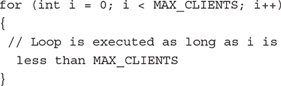
Program loops such as the for statement may also need curly braces:

It is also good practice to use braces in control structures such as the if statement:

Arithmetic Operators
![]()
=. The equals sign is the assignment operator used to set a variable to a value. For example, the following code sets the values of the access point name and the access point password. The variable ssid is set to ESP-01 and the pwd variable is set to esp8266esp01.
String ssid = "ESP-01";
String pwd = "esp8266esp01";
![]()
+. The plus sign performs addition between numbers. It can also be used in other contexts depending on how the addition operator is defined. For example, the following code builds a command string used to execute a command on the ESP-01. The plus sign is used to concatenate different String objects to form a final string. Here the ssid and the password for an access point are used to build the final string held in the variable APConfigCommand.
String APConfigCommand = "AT+CWSAP_CUR=";
APConfigCommand += """ + ssid + """ +
"," + """ + pwd + """ + ",";
![]()
−. The minus sign performs subtraction. For example, the following code calculates the time that has passed since the last ping was sent to the server. The time that has passed is held in the variable TimeDelayed. If the time that has elapsed is greater than the value in the PingInterval variable then a ping is sent to the server.

![]()
*. The asterisk sign performs multiplication. For example, the following code calculates the ping interval in milliseconds which totals 30 seconds or 30,000 milliseconds.
unsigned int PingInterval = 1000 * 30;
![]()
/.
float Speed = NumberMiles / NumberHours;
![]()
%. The percent sign is the modulo operator that returns the remainder from a division between two integers. For example:
int remainder = dividend % divisor;
Comparison Operators
![]()
==. The double equals sign is a comparison operator to test whether the argument on the left side of the double equals sign is equal to the argument on the right side. If the arguments are equal, then it evaluates to true. Otherwise, it evaluates to false. For example, the following code goes through a list of clients that may be connected to a server and looks for a client with a specific connection ID. If this connection ID is found then the client is processed.

![]()
!=. The exclamation point followed by an equals sign is the not-equal-to operator that evaluates to true if the argument on the left is not equal to the argument on the right side. Otherwise, it evaluates to false. For example, the following code searches through the array that keeps track of the clients that are connected to an access point. If a valid client is found then it is processed. Specifically if the client’s connection ID is not equal to the null string which means that the client is connected to the access point then process this valid client.

![]()
<. The less than operator evaluates to true if the argument on the left is less than the argument on the right. For example, in the code below, the for loop is executed as long as i is less than MAX_CLIENTS.
![]()
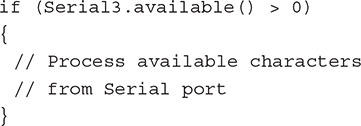
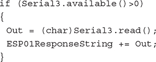
>. The greater than operator evaluates to true if the argument on the left side is greater than the argument on the right side. For example, in the following code, if the available() function returns a result that is greater than 0 then there are characters to read from the serial port, so the code block executes. That is, the number of available characters to read must be greater than 0.
![]()
<=. The less than sign followed by an equals sign returns true if the argument on the left side is less than or equal to the argument on the right side. It returns false otherwise.
![]()
>=. The greater than sign followed by an equals sign returns true if the argument on the left side is greater than or equal to the argument on the right side. It returns false otherwise.
Boolean Operators
![]()
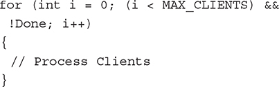
&&. This is the AND boolean operator that only returns true if both the arguments on the left and right sides evaluate to true. It returns false otherwise. For example, in the following code, the for loop is executed as long as the variable i is less than the maximum number of clients and the processing is not done yet.
![]()
||. This is the OR operator and returns true if either the left-side argument or the right-side argument evaluates to true. Otherwise, it returns false. For example, in the following code, if the incoming data from a client is equal to ledon or ledoff then the code block is executed and the command from the client is processed.

![]()
!. The NOT operator returns the opposite boolean value. The not value of true is false, which is 0, and the not value of false is true, which is nonzero. In the following code, a file is opened on the SD card, and a pointer to the file is returned. If the pointer to the file is NULL, which has a 0 value, then not NULL would be 1, which is true. The if statement is executed when the argument is evaluated to true, which means that the file pointer is NULL. This means that the Open operation has failed, and an error message needs to be displayed.

Bitwise Operators
![]()
&. This is the bitwise AND operator between two numbers, where each bit of each number has the AND operation performed on it to produce the result in the final number. The resulting bit is 1 only if both bits in each number are 1. Otherwise, the resulting bit is 0.
![]()
|. This is the bitwise OR operator between two numbers, where each bit of each number has the OR operation performed on it to produce the result in the final number. The resulting bit is 1 if the bit in either number is 1. Otherwise, the resulting bit is 0.
![]()
^. This is the bitwise XOR operator between two numbers, where each bit of each number has the exclusive OR operation performed on it to produce the result in the final number. The resulting bit is 1 if the bits in each number are different and 0 otherwise.
![]()
~. This is the bitwise NOT operator, where each bit in the number following the NOT symbol is inverted. The resulting bit is 1 if the initial bit was 0 and is 0 if the initial bit was 1.
![]()
<<. This is the “bitshift left” operator, where each bit in the left operand is shifted to the left by the number of positions indicated by the right operand. For example, in the following code, a 1 is shifted left PinPosition times, and the final value is assigned to the variable ByteValue:
ByteValue = 1 << PinPosition;
![]()
>>. This is the “bitshift right” operator, where each bit in the left operand is shifted to the right by the number of positions indicated by the right operand. For example, in the following code, bits in the number 255 are shifted to the right PinPosition times, and the final value is assigned to the variable ByteValue:
ByteValue = 255 >> PinPosition;
Compound Operators
![]()
++. This is the increment operator. The exact behavior of this operator also depends on whether it is placed before or after the variable being incremented. In the following code, the variable PhotoTakenCount is incremented by 1:
PhotoTakenCount++;
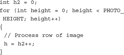
![]() If the increment operator is placed after the variable being incremented, then the variable is used first in the expression it is in before being incremented. For example, in the following code, the
If the increment operator is placed after the variable being incremented, then the variable is used first in the expression it is in before being incremented. For example, in the following code, the height variable is used first in the for loop expression before it is incremented. So the first iteration of the for loop below would use height = 0. So the first iteration of the for loop below would assign h = 0. The h2 variable would be incremented after being used in the expression and assigned to h.
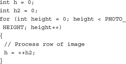
![]() If the increment operator is placed before the variable being incremented, then the variable is incremented first, and then it is used in the expression that it is in. For example, in the following code, the
If the increment operator is placed before the variable being incremented, then the variable is incremented first, and then it is used in the expression that it is in. For example, in the following code, the h2 variable is incremented first before it is used in the for loop. This means that in the first iteration of the loop, the h variable is 1.
![]()
--. The decrement operator decrements a variable by 1, and its exact behavior depends on the placement of the operator either before or after the variable being decremented. If the operator is placed before the variable, then the variable is decremented before being used in an expression. If the operator is placed after the variable, then the variable is used in an expression before it is decremented. This follows the same pattern as the increment operator discussed previously.
![]()
+=. The compound addition operator adds the right operand to the left operand. This is actually a shorthand version of operand1 = operand1 + operand2, which is the same as the version that uses the compound addition operator:
operand1 += operand2;
![]()
-=. The compound subtraction operator subtracts the operand on the right from the operand on the left. For example, the code for a compound subtraction would be
operand1 -= operand2;
This is the same as
operand1 = operand1 − operand2;
![]()
*=. The compound multiplication operator multiplies the operand on the right by the operand on the left. The code for this is
operand1 *= operand2;
This is also equivalent to
operand1 = operand1 * operand2;
![]()
/=. The compound division operator divides the operand on the left by the operand on the right. For example,
operand1 /= operand2;
This is equivalent to
operand1 = operand1 / operand2;
![]()
&=. The compound bitwise AND operator is equivalent to
x = x & y;
![]()
!=. This compound bitwise OR operator is equivalent to
x = x | y;
Pointer Access Operators
![]()
*. The dereference operator allows you to access the contents to which a pointer points. For example, the following code declares a variable pdata as a pointer to a byte and creates storage for the data using the new command. The pointer variable pdata is then dereferenced to allow the actual data to which the pointer points to be set to 1:
byte *pdata = new byte;
*pdata = 1;
![]()
&. The address operator creates a pointer to a variable. For example, the following code declares a variable data of type byte and assigns the value of 1 to it. A function called FunctionPointer() is defined that accepts as a parameter a pointer to a byte. In order to use this function with the variable data, we need to call that function with a pointer to the variable data:

Variable Scope
![]()
Global variables. In the Arduino programming environment, global variables are variables that are declared outside any function and before they are used. The following variables are global variables that represent the information needed in order to configure an access point on an ESP-01 module that uses the ESP8266 Wi-Fi communications chip.
// AP configuration parametersString ssid = "ESP-01";String pwd = "esp8266esp01";int chl = 1;int ecn = 2; int maxconn = 4;int ssidhidden = 0;
![]()
Local variables. Local variables are declared inside functions or code blocks and are only valid inside that function or code block. For example, in the following function, the variable localnumber is only visible inside the Function1() function:

Conversion
![]()
char(x). This function converts a value x into a char data type and then returns it.
![]()
byte(x). This function converts a value x into a byte data type and then returns it.
![]()
int(x). This function converts a value x into an integer data type and then returns it.
![]()
word(x). This function converts a value x into a word data type and then returns it.
![]()
word(highbyte,lowbyte). This function combines two bytes, the high-order byte and the low-order byte, into a single word and then returns it.
![]()
long(x). This function converts a value x into a long and then returns it.
![]()
float(x). This function converts a value x into a float and then returns it.
Control Structures
![]()
if (comparison operator). The if statement is a control statement that tests whether the result of the comparison operator or argument is true. If it is true, then execute the code block. For example, in the following code, the if statement tests to see whether more data from a Wi-Fi connection needs to be read. If so, then read the data in, and assign it to the Out character variable. There is more data available if the return value from Serial3.available() is greater than 0.
![]()
if (comparison operator) else. The if else control statement is similar to the if statement except with the addition of the else section, which is executed if the previous if statement evaluates to false and is not executed. For example, in the following code, if the command to the ESP-01 module is successfully performed then print out a message to the Arduino’s Serial Monitor indicating that the module’s state was changed to allow multiple client connections. Otherwise, print out a message indicating that the command failed.

![]()
for (initialization; condition; increment). The for statement is used to execute a code block usually initializing a counter and then performing actions on a group of objects indexed by that incremented value. For example:

![]()
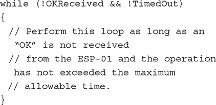
while (expression). The while statement executes a code block repeatedly until the expression evaluates to false. In the following code, the while code block is executed as long as an “OK” is not received from the ESP-01 module and the operation has not timed out due to exceeding the maximum allowable time.
![]()
break. A break statement is used to exit from a loop such as a while or for loop. In the following code, the while loop causes the code block to be executed forever. If data are available from the Serial Monitor, then they are processed, and then the while loop is exited:

![]()
return (value). The return statement exits a function. It also may return a value to the calling function:
return;return false;
Object-Oriented Programming
The Arduino programming environment also supports the object-oriented programming aspects of C++. An example of Arduino code that uses object-oriented programming is the WiFiClient class that supports Wi-Fi communication on the Arduino. A C++ class is composed of data, functions that use that data, and a constructor that is used to create an object of the class. An example of class data is
uint16_t _socket;
An example of a class constructor is
WiFiClient(uint8_t sock);
An example of a class function is
virtual void stop();
The following code is the WiFiClient class from the standard built-in Arduino Wi-Fi library.

Arduino Development System Requirements
Developing projects for the Arduino can be done on the Windows, Mac, and Linux operating systems. The software needed to develop programs that run on the Arduino can be downloaded from the main web site at http://www.arduino.cc/en/Main/Software.
The following is a summary of the different types of Arduino IDE distributions that are available for download. You will only need to download and install one of these files. The file you choose will depend on the operating system your computer is using.
Windows
![]() Windows Installer – This is a .exe file that must be run to install the Arduino IDE.
Windows Installer – This is a .exe file that must be run to install the Arduino IDE.
![]() Windows ZIP file for non admin install – This is a zip file that must be uncompressed in order to install the Arduino IDE. 7-zip is a free file compression and uncompression program is available at http://www.7-zip.org.
Windows ZIP file for non admin install – This is a zip file that must be uncompressed in order to install the Arduino IDE. 7-zip is a free file compression and uncompression program is available at http://www.7-zip.org.
Mac
![]() Mac OS X 10.7 Lion or newer – This is a zip file that must be uncompressed and installed for users of the Mac operating system.
Mac OS X 10.7 Lion or newer – This is a zip file that must be uncompressed and installed for users of the Mac operating system.
Linux
![]() Linux 32 bits – Installation file for the Linux 32 bit operating system.
Linux 32 bits – Installation file for the Linux 32 bit operating system.
![]() Linux 64 bits – Installation file for the Linux 64 bit operating system.
Linux 64 bits – Installation file for the Linux 64 bit operating system.
The Arduino Web Editor
You can now create Arduino sketches online through your web browser and save your program to cloud storage. The only downside is that you don’t have control over your programs or the Arduino IDE so that if the web editor is down or the cloud storage system is down you will either lose your data or not have access to your data until the site is back up.
Arduino Software IDE
This is the program that is used to develop the program code that runs on and controls the Arduino. For example, in order for you to have the Arduino control the lighting state of an LED you will need to write a computer program in C/C++ using the Arduino IDE. Then, you will need to compile this program into a form that the Arduino is able to execute and then transfer the final compiled program using the Arduino IDE. From there the program automatically executes and controls the LED that is connected to the Arduino. New versions of the IDE are compiled daily or hourly and are available for download. Older versions of the IDE are also available for downloading at http://www.arduino.cc/en/Main/OldSoftwareReleases.
In this section we will go over the key features of the Arduino Software IDE. The IDE you are using may be slightly different than the version discussed in this section but the general functions we cover here should still be the same. We won’t go in depth into every detail of the IDE since this book is meant as a quick start guide and not a reference manual. We will cover the critical features of the Arduino IDE that you will need to get started on the projects in this book. See Figure 1-14.

Figure 1-14 The Arduino IDE.
The “Verify” button checks to see if the program you have entered into the Arduino IDE is valid and without errors. These programs are called “sketches.” See Figure 1-15.

Figure 1-15 The Verify button.
The “Upload” button first verifies that the program in the IDE is a valid C/C++ program with no errors, compiles the program into a form the Arduino can execute, and then finally transfers the program via the USB cable that is connected from your computer to your Arduino board. See Figure 1-16.

Figure 1-16 The Upload button.
The “New” button creates a new blank file or sketch inside the Arduino IDE where the user can create his own C/C++ program for verification, compilation, and transferring to the Arduino. See Figure 1-17.

Figure 1-17 The New File button.
The “Open” File button is used to open and load in the Arduino C/C++ program source code from a file or load in various sample source codes from example Arduino projects that are included with the IDE. See Figure 1-18.

Figure 1-18 The Open File button.
The “Save” button saves the sketch you are currently working on to disk. A file save dialog is brought up first and then you will be able to save the file on your computer’s hard drive. See Figure 1-19.
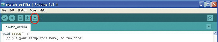
Figure 1-19 The Save File button.
The “Serial Monitor” button brings up the Serial Monitor debug program where the user can examine the output of debug statements from the Arduino program. The Serial Monitor can also accept user input that can be processed by the Arduino program. See Figure 1-20.

Figure 1-20 The Serial Monitor button.
There are also other important features of the main window of the Arduino IDE. The title bar of the IDE window contains the Arduino IDE version number. In Figure 1-21 the Arduino version number is 1.8.4. The sketch name is displayed in the source code tab and is “ESP01-Server-WithATCommands.” The source code area, which is the large white area with scrollbars on the right side and bottom, is where you enter your C/C++ source code that will control the behavior of the Arduino. The bottom black area in the IDE is where warning and errors are displayed from the code verification process. At the bottom left-hand corner of the IDE is a number that represents the line number in the source code where the user’s cursor is currently located. In the lower right-hand corner of the IDE is the currently selected Arduino model and COM port that the Arduino is attached to. See Figure 1-21.

Figure 1-21 The Arduino IDE.
Hands-on Example: A Simple Arduino “Hello World” Program with an LED
In this hands-on example I show you how to set up the Arduino development system on your Windows-based PC or Mac. I first discuss where you can get an Arduino board and USB cable. Then I discuss the installation of the Arduino IDE and Arduino hardware device drivers. I then discuss how to load in the “Blink” sketch example program. Next, I tell you how to verify that the program is without syntax errors, how to upload it onto the Arduino, and how to tell if the program is working.
Get an Arduino Board and USB Cable
You can purchase an official Arduino Mega 2560 board from http://www.arduino.cc. A second option is to buy an unofficial Arduino Mega 2560. These boards are generally a lot cheaper than an “official” Arduino board. However, the quality may vary widely between manufacturers or even between production runs between the same manufacturer. In terms of the USB cable that is used to connect the Arduino to your development computer the official Arduino board generally does not come with a cable but many unofficial boards come with short USB cables. Arduino compatible USB cables of a longer length such as 6 foot or 10 foot can be bought on Amazon.com or ebay.com. Make sure you get the right kind of USB cable with the right connectors on either end. The rectangular end of the USB cable is connected to your computer and the square end is connected to your Arduino. See Figure 1-22.

Figure 1-22 Arduino USB cable.
Install the Arduino IDE
The Arduino IDE has versions that can run on the Windows, Mac, and Linux operating systems. The Arduino IDE can be downloaded from http://www.arduino.cc/en/Main/Software.
I recommend installing the Windows executable version if you have a Windows-based computer. Follow the directions in the pop-up windows.
Note: The Arduino web site also contains links to instructions for installing the Arduino IDE for Windows, Mac, and Linux on http://www.arduino.cc/en/Guide/HomePage. The installation for Linux depends on the exact version of Linux being used.
Install the Arduino Drivers
The next step is to connect your Arduino to your computer using the USB cable. If you are using Windows it will try to automatically install your new Arduino hardware. Follow the directions in the pop-up windows to install the drivers. Decline to connect to Windows Update to search for the driver. Select “Install the software automatically” as recommended. If you are using XP ignore the pop-up window warning about the driver not passing windows logo testing to verify its compatibility with XP. If this does not work then instead of selecting “Install the software automatically” specify a specific driver location which is the “drivers/FTDI” directory under your main Arduino installation directory. For some operating systems like Windows 10 the drivers may already be installed by default. I personally noticed that my Android and Arduino devices were automatically recognized by the Windows 10 operating system.
Loading in the Blink Arduino Sketch Example
Next, we need to load the Blink sketch example into the Arduino IDE. Click the “Open” button to bring up the menu. Under “01. Basics” select the “Blink” example to load in. See Figure 1-23
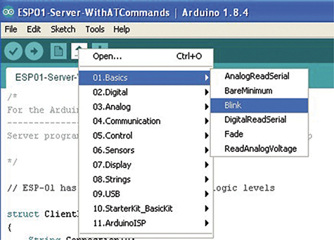
Figure 1-23 Loading in the blink example.
The code that is loaded into the Arduino IDE should look like the code in Listing 1-1.
Listing 1-1 Blink Sketch

Verifying the Blink Arduino Sketch Example
Click the “Verify” button to verify the program is valid C/C++ code and is error-free. See Figure 1-24.
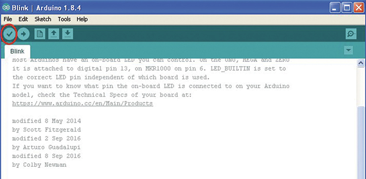
Figure 1-24 Verifying the Blink sketch.
Uploading the Blink Arduino Sketch Example
Before uploading the sketch to your Arduino make sure the type of Arduino under the “Tools->Board” menu item is correct. In our case the board type should be set to be “Arduino/Genuino Mega or Mega 2560.” See Figure 1-25.

Figure 1-25 Setting the Arduino model.
Next, make sure the serial port is set correctly to the one that is being used by your Arduino. Generally Com1 and Com2 are reserved and the serial port that the Arduino will be connected to is Com3 or higher. See Figure 1-26.
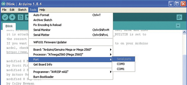
Figure 1-26 Set the com port if needed.
If you are using a Mac then the Serial Port selection should be something like “/dev/tty.usbmodem” instead of a COMXX value.
Next, with the Arduino connected press the “Upload” button to verify, compile, and then transfer the Blink example program to the Arduino. After the program has finished uploading you should see a message that the upload has been completed in the warnings/error window at the bottom of the IDE inside the black window. See Figure 1-27.
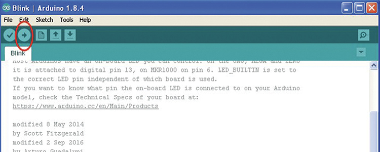
Figure 1-27 Upload to the Arduino.
Note: The Upload button does the job of the “Verify” button but also uploads the final compiled program to the Arduino.
The Final Result
The final result will be a blinking light on the Arduino board near digital pin 13. By design the Arduino board has a built-in LED connected to pin 13. So this example did not require you to connect an actual separate LED to the Arduino board. See Figure 1-28.

Figure 1-28 Blinking LED light.
Summary
In this chapter I introduced the Arduino to the reader. I concentrated my coverage on the Arduino Mega 2560. I discussed the Mega 2560’s basic features and then covered key functional components. I then gave a brief summary of the programming languages you will need to create programs with the Arduino. Next, information about the software needed to develop programs for the Arduino, called the Arduino IDE, was presented, including the different versions of the IDE available for different platforms. Information about key features of the IDE was discussed. Finally, a hands-on example was presented where I took the reader through a step-by-step guide to setting up the Arduino with a development computer system. In this example I also discussed loading in an example program, uploading this example program to the Arduino, and checking for the correct operation of the program.