
4 Design for Manufacturing Automotive Components
A Knowledge-Based Integrated Approach
Sudhanshu Bhushan Panda, Antaryami
Mishra, and Narayan Chandra Nayak
Indira Gandhi Institute of Technology
Contents
4.3 Experiments and Optimization
4.3.2 Part Design Optimization
4.1 Introduction
The automotive sector provides a vast market for industry verticals those elaborate in designing, manufacturing, and evolution of products, marketing, and selling of motor vehicles. The most challenging issue is to produce quality components that must meet all the application conditions, global standards, and are best in price and time [1,2]. This could be achieved by number of facts and figures: one of these is the best part design for the particular component with respect to its applications, standards, and acceptable unit cost. And the second most significant factor is to have reliable tool design that anticipated for defect-free part during injection molding production. The expanding markets for plastic materials and its application into today’s competitive fast-growing areas such as consumer electronics, automotive, and appliances compel to produce parts with emerging quality, cost, and in limited time. That eagerly looking for alternatives to produce flawless parts, it is required to forecast the product quality before investing in manufacturing in terms of cost and time, which is the call at present to compete in market. The quality of injection molded components at a large depends on the processing variables of the process. It is complicated and inclusive of many process characteristics, for instance, temperature, time, and pressure. Modifying any of such variables will affect one or all, as they are interrelated with each other. To maximize the production capacity and quality of parts, the processing parameters need to be optimized. Designers/engineers are assisted by advanced software tools for injection mold flow simulations to visualize the problem areas and decide suitable injection molding process values. So, depending on observation, unreasonable or empirical method can be eliminated [3,4]. The most familiar process used to produce polymer components is the injection molding technique. It is one of the principal commercial activities for producing complex, net-shaped, three-dimensional (3D) plastic components [5]. In general, the technique of injection process covers polymer part planning, tool planning or design, and injection process parameter characterization, those all playing a major role in delivering the quality product and efficient production. Molding process of injection technique is generally segregated into five basic stages: melting, stuffing, packing, cooling, and ejection [4,6, 7 and 8]. Mold cavities are required to be filled in a uniform time so as to get quality part [9]. Injection molding involves numerous parameters for part and tool design that need to be considered in an integrated and concurrent approach. It is also equally important to have flexibility in designing solid models for parts and molds by simultaneously incorporating design intent and optimization results. This system of design covers modules for calculation and selection of mold components. It makes use of advanced modern techniques associated with computer-aided design (CAD) software and simulation results as inputs for selection, modification, and design. It has been also analyzed by computer-aided design and engineering (CAD/CAE) integration [4,10, 11 and 12]. The geometric features and design intent of plastic parts are also investigated through CAD/CAE for related analysis. Product geometry, in general, includes the information of a plastic product regarding its section thickness and mounting attributes such as ribs, bosses, guesses, chamfers, and holes; and the engineering attributes comprise interpretation-related information on design and sub-wall/evolve elements. It is also seen as a CAE structure for tool planning as well as manufacturing and variable computation for injection molding process [11]. Morphology matrix and decision diagrams are applied to analyze the process. All these processes are cast-off for rheological, mechanical and thermal computations, and raw material particulars and its details, but there it is not associated with computer-aided software tool [4,13]. Based on parametric and feature recognition, advanced software tools were used for 3D part modeling and mold base creation for plastic injection molding design system. This software provides a communicative platform to assist designers in quick creation of part modeling and tool planning and foster to make it a standardized process of mold design and planning. The software has options for calculations for number of impressions, mold components and dimensional verifications, and choice of injection molding machine. The orthodox unproved practice is costly, time-consuming, and insignificant. To make better tool plan, process controlling of injection molding variables and getting larger credence in CAD and CAE is required [6]. The tool design structure was developed by employing an unbarred application program interface (API) and mercantile computer-aided design, manufacturing and engineering (CAD/CAM/CAE) solutions [10,12,14]. Product designers were able to optimize part shape and sizes, and, at the same time, tool designers could optimize mold design systems. CAE principle is used to compute mold design and injection molding parameters with the help of numerical simulations. This is possible because of countless studies that were done on CAE software to study mold and characterization of injection molding processes. Regardless, each one of the earlier proposed procedure is not capable of forecasting the tool design and polymer injection process characteristics. This leads to draw the need of developing a software structure with unified process attributes and which can verify with the consequences based on computation and simulation of polymer molding, tool verification, and choice alternatives. Each of the research studies can be combined together for CAD and CAE integration of tool design process for polymer components [4,12]. For a prolonged time, number of researchers concentrated on tool designing of polymer injection molded parts facilitated with computers and software tools. Several researchers have made headway to series of measures that facilitated professionals and engineers to design components, tools, and deciding factors for characteristics of polymer molding in injection process. In the meantime, researchers also explored the standardization and integration of plastic injection mold design with CAD and engineering system of design, development, calculations, and modifications [4]. Many researchers enlightened mold flow simulation to optimize injection molding parameters only, but no research has been done to optimize the plastic part design and tool design as an associative integrated technique from CAD software and mold flow simulation results [4].
4.1.1 The Investigated Part
In this research, an injection molded part is analyzed for flawless production from an original automotive vehicle manufacturer [3]. There are numerous visual and functional defects with the investigated part, such as sink marks appear on class A surface, which is not acceptable. Further, the flashes, deep machining marks, and other manufacturing scratches and defects should be positively avoided without changing the class A surface. There is a scope to investigate part design and tool design to eliminate all the visible defects or distortions during injection molding [10]. The injection molding process parameters also need to be taken into account to improve the processing defects [1,15]. Mold flow simulation helps designers to predict product designs without actual injection molding processing that saves time and cost [16].
4.1.2 Objectives
The specific purpose of this investigation is aimed at
predicting problem areas of mold flow plastic part advisor;
determining the design experiments (DOE) and iterations of geometrical shape and size of the part to get optimized design.
4.2 Materials and Methodology
The plastic raw material used for this experimental analysis was A3WG6 (Ultramid)-BK00564, which is the reinforcement of 30% glass fiber; black pigment, which enhances heat and aging hostility to PA66-injection molding grade; housings and components for machines, which have high stiffness and dimensional stability. This engineering polymer is suitable for automobile component applications in harsh environmental conditions. This selected polymer has distinctive industrial uses, for example, for making vessels for automobile cooling systems, encase silhouette for window frames of aluminum, in cooling fans, and for making housings for light sockets [17]. The experiment was conducted using the 3D CAD data from the existing plastic part. The CAD data were acquired using Pro/ENGINEER software, which is commercially available for modeling and designing a variety of products [13]. The experimental part is optimized on geometrical dimensions, and the 3D CAD model is developed with help of the software. DOE has been done on part geometrical shape and size of the CAD model and is analyzed and optimized through mold flow plastic part advisor, an integrated simulation tool within Pro/ENGINEER software. The suggested methodology blends this Pro/ENGINEER tool with an especially evolved factor for the computation of polymer molding values, tool planning, and preference of tool components. This process of coalition employs invariable and CAD/CAE attributes to establish organized information to smoothen the procedure of reviewing, editing, and designing [18]. Generally, the output results and part structure drawn out of the CAD/CAE unified injection molding design structure are quite efficient and reliable [4,13]. Nevertheless, putting into practice these simulation results helps in the development of processing variables to acquire an empirical procedure. In reality, ascertaining the enhanced process characteristics for manufacturing an improved version of standard injection molding polymer component, the simulation experiment should fetch as many iterations. Accordingly, this investigational course of actions is unmanageable and disordered [6]. As a consequence, to overcome these circumstances, improved procedures are commonly combined for simulation so as to assist professionals in reaching out optimum processing parameters for framing up and establishing injection molding process [3,4,6].
4.3 Experiments and Optimization
Tool design is a detailed congenial process that includes parametric, compatible, and feature-based integrated CAD/CAE system. Numerical simulation plays a major role and unlocks novel opportunities of part analysis in the course of the product and tool design. The part designing is analyzed and optimized by considering foremost process variables of injection molding for the specific plastic raw material as specified by the raw material manufacturer, BASF Corporation [17]. Further, by taking the results from the analysis as input, the part design get an optimized number of times till satisfactory results are obtained, and finally, the best optimized part design is anticipated. The motivation behind presiding over the evaluation is to distinguish and adopt the correlated molding characteristics that influence mechanical values of the molded product. Within this research, mold flow plastic advisor analysis and calculations are used to perform all simulations. For the mold flow analysis, overall the part dimensions were taken as 225 mm length × 39 mm width × 44 mm height. This investigation considers the meshing model for simulation with 200,599 number of elements in part and 171,814 number of nodes. This research integrates 3D designing software tools with mold flow simulation tool and for validation it is based on the results of part geometry and design. The existing part is analyzed visually to notify all the possible defects and systematically categorized strenuously. The CAD data were imported to mold flow simulation platform.
All the injection molding process input data to carry out the analysis are considered to hold the raw material manufacturer’s data information sheet for the material: Ultramid A3WG6–PA66–GF 30, 180 MPa as injection pressure, 290°C as melt temperature, 85°C as mold temperature, and the density of the part is taken as 1.36 g/cm3 [17].
Material selection and conformity to recognized standards of data play a major role in delivering the best results [1]. A balanced understanding is required to match the process and material parameters. The various stages of injection molding part design, to avoid quality issues, are depicted in a logical flow diagram, as shown in Figure 4.1. Most of the injection molding components of the complex, 3D structural profiles, and the rheological characteristics of the molten plastic do not adhere to Newtonian and isothermal laws. With these multiple unprecedented problems in computational analyses, mainly during the process of filling, precautions were required to be taken [19].

FIGURE 4.1 Flow chart of part defect analysis.
The injection molding variables, namely, the temperature of polymer melt, pressure of injection, pressure of holding, mold temperature, and filling duration, are important parameters to consider during molding process [13]. The mold flow virtually has been done in the experiments to foresee the problem areas in the particular part, and subsequently inputs are taken to modify the part geometry and design.
A number of iterations were done on part design till the best results were achieved from the simulation experiment. This activity was repeated till satisfactory results in terms of part design and molding process parameter values were acquired.
4.3.1 Analysis of the Part
The 3D parametric CAD data were fetched from Pro/ENGINEER software and analyzed using Mold flow Plastic Part Advisor for preferable part design and to predict injection molding process parameters. Following observations were noted after multiple workouts of the product.
More sink marks are concentrated at the top surface, as shown in Figure 4.2a, blue-shaded color gradually changes to green, yellow, orange, and finally to red color shades indicating severe shrinkage marks on functional class A face, which could be visible with the tangible product and in connection with the result of simulation published. In Figure 4.2b, the filling time of cavities is indicated in seconds. Figure 4.2c reflects non-uniformity pressure for injection dispersal in the course of injection processing (red to blue tone shading) while utmost pressure for injection is equitable. In Figure 4.2d, drop in pressure at one end is visible from red tone, which is also required to be fairly in proportion. The area in color yellow reflects inferior standard of the part, which could be due to increased wall thickness as compared with other sections of the component, as illustrated in Figure 4.2e. According to the simulation results, the polymer weld marks are liable to rupture [20] at mentioned specific location of metallic part as clearly visible opposite to ribs as well as feeding point (shown in Figure 4.2f), which states the need of reducing the marks as much as feasible. In Figure 4.2g, the gas-trap is shown, which is the foremost vital feature for injection part value and class. This necessitates the part to leave the mold cavity in course of packing stage to get rid of bubbles in the component, which in aftermath degrades the part strength and introduces defective components [2]. Figure 4.2h points out the cooling status of the part toned with red shades, which implies indigent part section geometry and thickness at those locations that have to be eliminated by keeping invariable part thickness, and, if possible, to lessen the thickness particularly on affected regions.

FIGURE 4.2 Mold flow analysis for existing part. (a) Shrinkage area. (b) Fill time. (c) Injection pressure. (d) Pressure drop. (e) Quality prediction. (f) Weld lines. (g) Air traps. (h) Cooling quality.
4.3.2 Part Design Optimization
After a brief design of geometrical shape and size iterations, it is found that the most favorable part design is represented as follows:
For the sake of the refinement of the product, the results of analysis data should be linked with the drawbacks of the part. The specific reasons were studied and the end result is listed here for the enhancement of the component.
Design of ribs
In Figure 4.3a and b, it is shown that the part has irregular wall thickness and bulky section at top, which creates more sink mark on class A surface. But the maximum rib thickness should be at t = 0.75 T, where “T” is the general section thickness of the product that should be taken to avoid sink mark at rib section area [21,13].
For better control of sink marks, ribs should be thin, as shown in Figure 4.4a and b, compared with existing design and the gap between the ribs be increased to minimize the sink mark and to retain the required strength. All the edges and corners should be filleted for better plastic flow and minimal stress development, as the rib design affects the part strength and durability of the part with respect to its application [21].
Insert molding
The metal insert outer wall is not uniform, as shown in Figure 4.5a and b, for which sink marks are heavily seen just opposite to its placement, on top surface. According to the simulation results, shown in Figure 4.2a, sink marks are accumulated in this area.
The metal insert with respect to the top wall thickness and around it is maintained uniform and kept of minimum possible thickness so as to avoid sink marks during molding [13], as shown in Figure 4.6a and b. To keep minimum wall thickness for better control of sink marks, the bulky gathering of polymers is avoided, as shown with the existing part shown in Figure 4.5.
Wall thickness
The overall wall thickness variations on the part (Figure 4.7), being the crucial obstacle to the plastic melt flow together with correlative composition of component at discrete sections, create the very large shrinkage spots and also impair the durability and standard grade of the product [22, 23 and 24]. The improved product design has prevailed over those all setbacks by maintaining uniform section thickness on these locations as shown in Figure 4.8.

FIGURE 4.3 Rib design with existing part.
FIGURE 4.4 Rib design with optimized part.
FIGURE 4.5 Metal insert design with existing part.
FIGURE 4.6 Rib and metal insert design with optimized part.
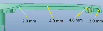
FIGURE 4.7 Existing part with variable wall thickness.
FIGURE 4.8 Optimized part with uniform wall thickness.
4.4 Results and Discussion
Brief results are obtained ofrom the “Mold Flow Plastic Product Advisor” analysis by running experiments repeatedly for a number of times on the software with the inputs for the specified raw material to get the new optimized part design.
The geometrical shape and size of the part is modified to get best possible outcome based on injection molding parameters as per the specification of particular plastic raw material. Once the CAD data are finalized, the part is analyzed through mega pascal (MPA), and after repeated number of cycles the best results are shown in Figure 4.9a–h.

FIGURE 4.9 MPA analysis of optimized part. (a) Sink area. (b) Fill time. (c) Injection pressure. (d) Pressure drop. (e) Quality prediction. (f) Weld lines. (g) Air traps. (h) Cooling quality.
The sink marks, as shown in Figure 4.9a, are minimized as compared with the existing part. The higher value of filling duration, as given in Figure 4.9b, regulates the concerned part’s quality [3]. The pressure for injection is almost balanced as shown in Figure 4.9c, and it signifies that the feeding point is at right location. Pressure drop, as shown in Figure 4.9 d, is related to the part section thickness and volume of the plastic part with respect to the feeding point. The analysis results for overall quality of the part are also better as compared with the existing part (Figure 4.9e). Weld lines, as shown in Figure 4.9f, inside the polymer deteriorate the toughness and durability of the component in real applications [1]. Weld zone is generally formed at the flow front of polymers inside the mold, where two or more directional polymer melts get converge. Air traps or voids, as shown in Figure 4.9g, appear inside the part during injection of molten polymer due to hindrance of gases from the mold. The comprehensive cooling quality [15,25], as shown in Figure 4.9h, implies the cooling provisions for cooling passages for cavities and cores, particularly while designing tool. While establishing the simulation outcomes, the values of melt temperature of polymer, pressure of packing, and duration for injection come were found significant [3,26].
The sink marks, as shown in Figure 4.9a, are reduced compared with the existing part design, and it shows the design and wall thickness have played an important role on sinking ability of the plastic parts. The analysis also helps to find out the short volume which was 43.4 cm3 and is reduced to 40.7 cm3, which is 6.22% less, as shown in Table 4.1; the filling time is 1.21 s, which is 8.33% less to the existing part; whereas the suitable injection pressure is calculated at 17.2 MPa, which is around 28% more than the existing. The simulation of part is also helpful for better packing of polymer inside the mold to get better mechanical properties of the molded component [11]. The clamping force is also increased to 11.2%, which is helpful for the part to be flash free [7,12,14,25]. The most important injection molding defect is due to sink of the polymer after molding [22]. Warpage is a prime factor that affects product quality [27]. Non-uniformity of cooling, shrinkage, and orientation are heavily influenced warpage [28]. The result here shows 58.62% of sink ability, which is improved with the new optimized part design, and more specifically class A surface has a minimum number of sink marks. The quality prediction is 37.8% better as compared with the existing part. The analysis result also indicates the cooling quality, as shown in Table 4.1, which has improved to 87%, which is 25.3% more than the existing part. Depending upon the gate location and the part design, the polymer flow front and joining are also improved [13] by virtue of which the weld quality of the plastic part gets improved.
Parameters |
Existing Part |
Optimized Part |
Remarks |
|---|---|---|---|
Raw material |
Ultramid A3WG6 |
Ultramid A3WG6 |
|
Maximum injection pressure (MPa) |
180 |
180 |
|
Mold temperature (°C) |
85 |
85 |
|
Melt temperature (°C) |
290 |
290 |
|
Shot volume (cm3) |
43.4 |
40.7 |
6.22% decrease |
Fill time (s) |
1.32 |
1.21 |
8.33% decrease |
Injection pressure (MPa) |
12.4 |
17.2 |
27.9% increase |
Filling clamp force (tonnage) |
4.44 |
5.0 |
11.2% increase |
Pressure drop |
Average |
Better and balanced |
|
Sinkability (%) |
29 |
12 |
17% decrease |
Sink marks (%) |
High on Class “A” surface |
Low on Class “A” surface |
|
Quality prediction (%) |
56 |
90 |
34% increase |
Cooling quality (%) |
65 |
87 |
22% increase |
Weld lines (%) |
12 |
5 |
7% decrease |
Air traps (%) |
30 |
20 |
10% decrease |
In this research, the part design, injection molding process parameters, etc. are well balanced to get the best results regarding weld lines. The weld lines are decreased to 58.4% as compared with the existing part. Earlier, the air trap inside the part during injection molding was also a significant defect to the quality of the part [12,25], and now it is also minimized, that is, it is reduced to 33.33% as compared with earlier part design. So, finally the new optimized injection molded part ensures better quality as compared with the existing design. The gate diameter or feeding opening plays an important role on quality of the injection molded part [7], particularly the sink marks. It is noticed the gate diameter of 3 mm in the existing part incorporated more sink marks, and when the gate diameter was reduced to 2 mm, the sink marks also reduced considerably. Unlike gate diameter, gate location has a considerable effect on the quality of injection molded part [29]. The gate location versus the percentage of sinkability is analyzed and the best gate location was found to be as 62 mm in x-direction and 6 mm in y-direction. The minimum possible sinkability is shown to be 22%, compared with other gate locations. Overall quality of the part is also analyzed by iteration of gate diameter and it is found that the best suited gate diameter for this particular part is 2 mm, and the best quality of the part is predicted at 85%. The gate location versus overall quality of the part has also been analyzed and the best quality of the part was found to be 85% with the gate locations finalized at 62 mm in x-direction and 6 mm in y-direction.
It is found that mold surface temperature and melt temperature are the prime process control parameters for warpage and sink marks [12,25] in injection molding of plastics. The factors influencing the quality of a molding component are design of part, design of mold, performance of machine, and conditions of processing [14]. Moldflow Insight Plastics software helps to investigate the factors affecting polymer part and tool designing during the time of injection molding process, for example, short impression, dissimilar filling, over packing, weld areas, etc. [8,26]. It also helps to keep away from bulky geometries by preserving similar section thickness to minimize the price of raw materials and as well machine time [20]. Mold simulation software contributes adequate statistics in respect of its duration for filling [2,9], pressure concerning injection, and pressure decreases [16], which could abstain from the defects in polymers, made from factual injection molding, like shrinkage points, air bubbles, and extra packing [18]. Many of these crucial decisions should be taken in the design phase of complex injection molding [27], which saves total costs and product timeline [22]. It is also concluded that by controlling the process parameters, the depth of a sink mark can be minimized or completely eliminated [23,24]. Implementation of CAD/CAE and CAM during manufacturing and design of tools for injection molding for the automobile parts followed by simulation [1,13,30] furnishes tool design engineers and concerned manufacturers with a considerate way of polymer behavior during the course of its solidification for the metallic insert component. So they are now able to correctly design and effectively use polymer solidification techniques. The optimized model could deliver correct outcomes by simulation results.
4.5 Conclusions
A virtual reality–based product designing method for plastic part design is developed that could save cost, time, man-hour, energy in this competitive and fast changing world. The times for filling and packing are closely related to each other, so they affect the sink marks and dimensional quality of the plastic part. The experimental work was much easier and time saving. This simulation mechanism in association with advanced software tools motivates engineers to assure their product design’s credence in production to compete into market. The proposed system also saves man-hour, resources, and minimizes efforts to produce injection molded parts. This virtual-reality system of techniques involves artificial intelligence principles before actual part production facilitates to compete in the process of plastic product development in today’s fast-changing technological markets. To conceive a sustainable product, it may carefully be exploited in designing the manufacturing methodology.
References
1. Mayyas, A., Qattawi, A., Omar, M., & Shan, D. (2012), Design for sustainability in automotive industry: A comprehensive review. Renewable and Sustainable Energy Reviews, 16(4), 1845–1862. doi:10.1016/j.rser.2012.01.012.
2. Katarína Szeteiova, I. (2010), Automotive materials: Plastics in automotive markets today, 27–33.
3. Mehat, N. M. & Kamaruddin, S. (2011), Investigating the effects of injection molding parameters on the mechanical properties of recycled plastic parts using the taguchi method. Materials and Manufacturing Processes, 26(2), 202–209, doi:10.1080/10426914.2010.529587.
4. Matin, I., Hadzistevic, M., Hodolic, J., Vukelic, D., & Lukic, D. (2012), A CAD/CAE-integrated injection mold design system for plastic products. The International Journal of Advanced Manufacturing Technology, 63(5–8), 595–607. doi:10.1007/s00170-012-3926-5.
5. Guo, W., Hua, L., Mao, H., & Meng, Z. (2012), Prediction of warpage in plastic injection molding based on design of experiments. Journal of Mechanical Science and Technology, 26(4), 1133–1139. doi:10.1007/s12206-012-0214-0.
6. Zhou, H., Shi, S., & Ma, B. (2009), A virtual injection molding system based on numerical simulation. The International Journal of Advanced Manufacturing Technology, 40(3–4), 297–306. doi:10.1007/s00170-007-1332-1.
7. Elsheikhi, S. A., & Benyounis, K. Y. (2016), Review of recent developments in injection molding process for polymeric materials. Reference Module in Materials Science and Materials Engineering. doi:10.1016/b978-0-12-803581-8.04022-4.
8. Chen, P.-H. A., Villarreal-Marroquín, M. G., Dean, A. M., Santner, T. J., Mulyana, R., & Castro, J. M. (2018), Sequential design of an injection molding process using a calibrated predictor. Journal of Quality Technology, 50(3), 309–326, doi:10.1080/00224065.2018.1474696.
9. Osswald, T. A., & Hernández-Ortiz, J. P. (2006), Polymer Processing - Modeling and Simulation, Hanser Gardner Publications, Cincinnati.
10. Nee, Andrew Y. C. (2003), Computer-aided tooling design for manufacturing processes. Annals of the CIRP, 46(3), 429–432.
11. Lee, S. H. (2009), Feature-based non-manifold modeling system to integrate design and analysis of injection molding products. Journal of Mechanical Science and Technology, 23(5), 1331–1341. doi:10.1007/s12206-009-0407-3.
12. Kohlhase, M., Lemburg, J., Schröder, L., & Schulz, E. (2010), Formal management of CAD/CAM processes. German Federal Ministry of Education and Research, 28(5), 16–32.
13. Grujicic, M., Sellappan, V., Pandurangan, B., Li, G., Vahidi, A., Seyr, N., … Holzleitner, J. (2008), Computational analysis of injection- molding residual-stress development in direct-adhesion polymer-to- metal hybrid body-in-white components. Journal of Materials Processing Technology, 203(1–3), 19–36. doi:10.1016/j.jmatprotec.2007.09.059.
14. Stoić, A., Kopac, J., Duspara, M., Micetic, I., & Stoic, M. (2013), Manufacturing of injection moulding tool with five axis milling machine. Journal of Achievements in Materials and Manufacturing Engineering, 58(01), 38–46.
15. Smith, A. G., Wrobel, L. C., McCalla, B. A., Allan, P. S., & Hornsby, P. R. (2008), A computational model for the cooling phase of injection moulding. Journal of Materials Processing Technology, 195(1–3), 305–313. doi:10.1016/j.jmatprotec.2007.05.018.
16. Chen, C.-P., Chuang, M.-T., Hsiao, Y.-H., Yang, Y.-K., & Tsai, C.-H. (2009), Simulation and experimental study in determining injection molding process parameters for thin-shell plastic parts via design of experiments analysis. Expert Systems with Applications, 36(7), 10752–10759. doi:10.1016/j.eswa.2009.02.017.
17. Product Information, Ultramid® A3WG6 BK00564 Polyamide 66 (2015), BASF Corporation, Engineering Plastics,1609 Biddle Avenue,Wyandotte, MI 48192.
18. Taha, I., & Abdin, Y. F. (2011), Modeling of strength and stiffness of short randomly oriented glass fiber—polypropylene composites. Journal of Composite Materials, 45(17), 1805–1821. doi:10.1177/0021998310389089.
19. El Otmani, R., Zinet, M., Boutaous, M., & Benhadid, H. (2011), Numerical simulation and thermal analysis of the filling stage in the injection molding process: Role of the mold-polymer interface. Journal of Applied Polymer Science, 121(3), 1579–1592. doi:10.1002/app.33699.
20. Barriere, T., Liu, B., & Gelin, J. C. (2003), Determination of the optimal process parameters in metal injection molding from experiments and numerical modeling. Journal of Materials Processing Technology, 143–144, 636–644. doi:10.1016/s0924-0136(03)00473-4.
21. Ozcelik, B., & Sonat, I. (2009) Warpage and structural analysis of thin shell plastic in the plastic injection molding. Materials & Design, 30(2), 367–375. doi:10.1016/j.matdes.2008.04.053.
22. Ghose, A., Montero, M., & Odell, D., (2015), Characterization of an injection molding process for improved part quality, Berkeley Manufacturing Institute, Dept. of Mechanical Engineering, University of California - Berkeley, 3 (2), 31–38.
23. Sykutera, D., & Bieliński, M. (2012), Application of CA systems at Design and simulation of plastic molded parts, Journal of Polish CIMAC, 4(1), 65–72.
24. Chun-Ying, Z., & Li-Tao, W., (2011), Injection mold design based on plastic advisor analysis software in Pro/E, International Conference, China, IEEE, 205–208, doi:10.1109/CMSP.2011.49.
25. Zhou, H., Yan, B., & Zhang, Y. (2008), 3D filling simulation of injection molding based on the PG method. Journal of Materials Processing Technology, 204(1–3), 475–480. doi:10.1016/j.jmatprotec.2008.03.017.
26. Kirchberg, S., Holländer, U., Möhwald, K., Ziegmann, G., & Bach, F.-W. (2012), Processing and characterization of injection moldable polymer-particle composites applicable in brazing processes. Journal of Applied Polymer Science, 129(4), 1669–1677. doi:10.1002/app.38862.
27. Panda, S. B., Nayak, N. C., & Mishra, A., (2017), Engineering polymers in automobile seat belt lock applications: It’s development, investigation and performance analysis. Journal of Production Engineering, 20(1), 63–68. doi:10.24867/JPE-2017-01-063.
28. Kovacs, J. G., & Siklo, B. (2011), Investigation of cooling effect at corners in injection molding. International Communications in Heat and Mass Transfer, 38(10), 1330–1334. doi:10.1016/j.icheatmasstransfer.2011.08.007.
29. Frick, A., & Spadaro, M. (2017), Mold design for the assembly injection molding of a solid housing with integrated dynamic seal. Polymer Engineering & Science, 58(4), 545–551. doi:10.1002/pen.24766.
30. Villarreal, M. G., Castro, M. J. M., & Cabrera-Ríos, M. (2011), A multicriteria simulation optimization method for injection molding, Proceedings of the 2011 Winter Simulation Conference, Arizona, USA, 2390–2402.