
Arduino is the name originally given, in 2005, to an Italian educational project intended to teach physical computing to industrial and commercial design students who did not have an electronics background. Raspberry Pi is the name given, in 2012, to a British educational project aiming to create a single-board computer that could be used to introduce basic computer science in the early phases of childhood education. In both projects, the creators reasoned that by offering very low-cost hardware, more students would have access to computer science and physical computing. As the two educational projects developed far beyond what was imagined possible at the time of their inceptions and introductions, the names have come to represent the hardware boards extensively in use today. Although both Arduino and Raspberry Pi were teaching concepts, they are very different devices with different purposes that display some overlapping capabilities. Each device is uniquely suited to its designed purpose.
Arduino
Originally envisioned as a digitally programmable electronic platform for designers to impart a human interaction option into their work, the Arduino had to be simple to use for those without formal training in electronics. Simplicity was achieved by the creation of the integrated development environment (IDE) software program. An IDE allowed the user to assemble a series of relatively simple basic instructions based upon the C programming language into an executable microcontroller program. The program created in the IDE was able to control the actions of a remote microcontroller, resident on a small circuit board, that provided augmented and extensive input and output capabilities plus electronic control of the design to which it was connected.
Additional simplicity for the Arduino board was achieved by using the USB connection to a host computer to eliminate having a complex operating system on the microcontroller boards, and to provide the computational and graphics capabilities required for the IDE program to assemble, debug, and transfer the code required for programming the board’s microcontroller. The program assembled in the IDE resident in the host PC that is downloaded to the Arduino to manage or collect data from sensors or peripherals is called a “sketch”.
The augmented input–output capabilities of the Arduino board were achieved by installing an accurate crystal-controlled time clock on the board, and using firmware and application-specific integrated circuitry to implement analog-to-digital conversion, digital input and output, pulse width modulation output, and 5- or 3.3-volt power, all under the control of an AVR ATmega328P 8-bit, 16 MHz microcontroller chip.
Arduino Uno Specifications
Microcontroller | ATmega328 |
|---|---|
Operating Voltage | 5V |
Input Voltage (recommended) | 7–12V |
Input Voltage (limits) | 6–20V |
Digital I/O Pins | 14 (of which 6 provide PWM output) |
Analog Input Pins | 6 |
DC Current per I/O Pin | 40 mA |
DC Current for 3.3V Pin | 50 mA |
Flash Memory | 32 KB (ATmega328) of which 0.5 KB used by bootloader |
SRAM | 2 KB (ATmega328) |
EEPROM | 1 KB (ATmega328) |
Clock Speed | 16 MHz (Arduino boards use a crystal clock) |
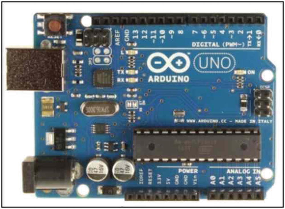
Arduino Uno
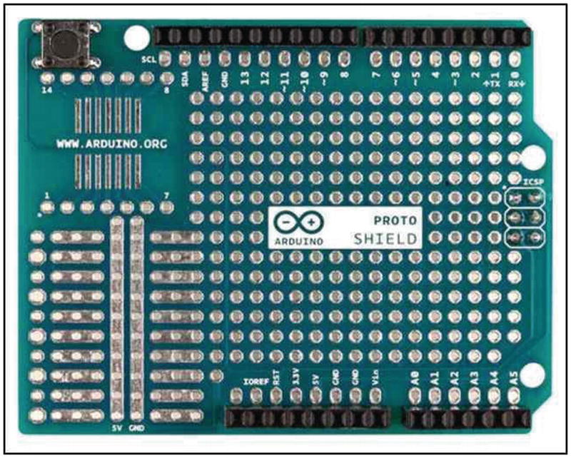
Top view of a blank Arduino shield

An Arduino shield with a small prototyping breadboard
The Arduino concept and evolving hardware are solely for physical computing when interfacing sensors or electro-mechanical peripherals to computing devices.
Raspberry Pi
The declining number of students entering the field of computer science led to the concept of creating a very inexpensive computer to increase student interest at the primary levels of education. A non-profit organization called the Raspberry Pi Foundation introduced the first model of the Raspberry Pi (RPi) computer in 2012. The project created and distributed a single-board computer (SBC) for $25 each. The original design has passed through four phases of revision, and as of November 2016 a reported 11 million devices have been sold.
Various Models of Raspberry Pi
-
|


Side view of the RPi model 3

Top view of the RPi model 3
The model 3 RPi is compatible with 802.11n wireless local area networks (LAN) communications, Bluetooth 4.1 communication, and near-field low-energy protocols.
A very low-cost device was made possible by eliminating virtually all the peripherals normally associated with a computer. All models of the RPi SBC need a power supply and keyboard, must use an SD card to hold the computer operating system, and require cables to connect any peripherals or networks to the processor. A high-definition multimedia interface (HDMI) allows the processor to interface to a wide variety of digital displays, including home televisions.
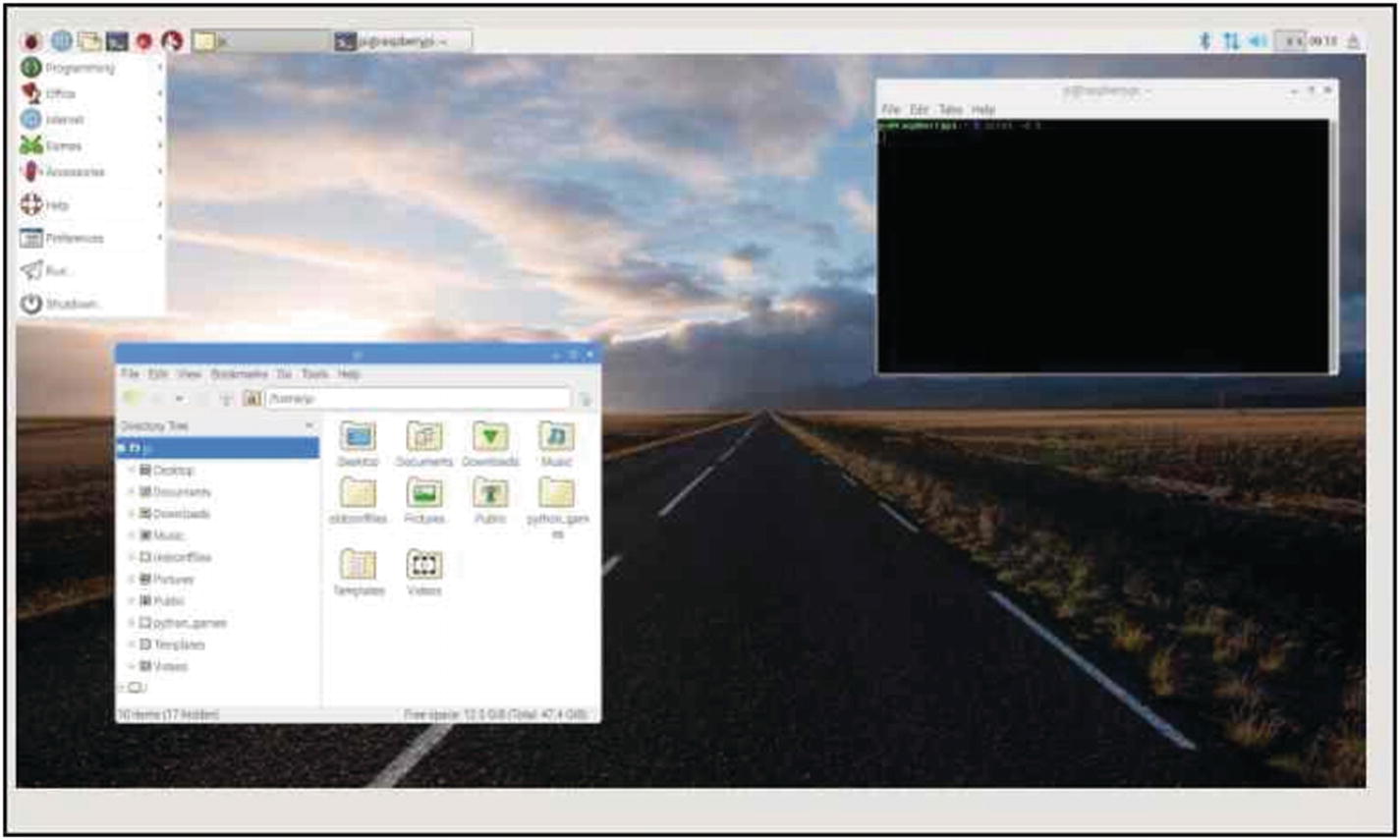
RPi Pixel “desktop” with the terminal program and file manager open
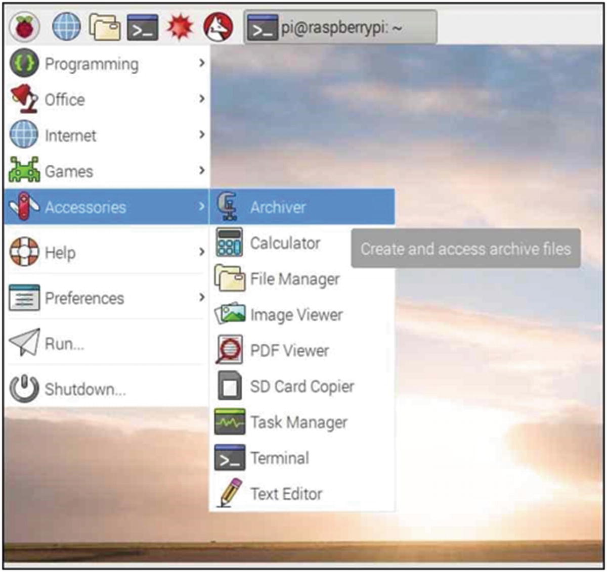
Pixel menus
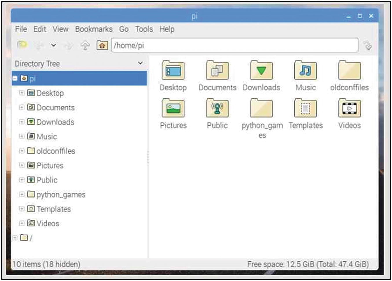
Pixel file manager

HAT Sense board emulator screen
Early models of the RPi were equipped with a dual row of thirteen pins that formed a twenty-six-pin array called the general purpose input–output (GPIO) array that enabled the CPU to communicate with peripherals connected to the pins. With the production of the Model B, a modification was made, and the Model B+ was introduced with a forty-pin GPIO array. Drawing from industrial practice, the newer RPi computing systems are able to load and recognize stackable add-on hardware boards that can be fitted over the forty-pin array. The add-on boards are known as hardware added on top (HAT). HATs are available for a large number of sensors, motors, liquid crystal displays, analog-to-digital converters, and a host of other applications, such as the multiple-sensor system depicted in Figure 1-9.
However, the RPi has some inherent limitations in the performance and use of the GPIO facility. The software operating system for the RPi can have a higher-priority process running at the same time as a GPIO operation, which can result in the temporary neglect of the input or output signal. The conflict can sometimes be seen as the “flickering” of LEDs controlled by the GPIO pin array.

RPi GPIO pin assignments
In summary, the GPIO array has twenty-six configurable pins labeled as GPIO 2 to 27 that can be programmed as either digital inputs or outputs. The array has four power pins, two at 5 volts and two at 3.3 volts, with eight ground connections. Two pins are assigned to serial communications. For implementing communications with single integrated circuits such as the MCP3008 analog-to-digital converter, the serial peripheral interface (SPI) protocol is used. (Implementation of the SPI protocol is achieved by selecting the SPI option from the Interfaces tab of the Raspberry Pi Configuration window. The Configuration window is accessed from the main menu by selecting the “Preferences” entry and then “Raspberry Pi Configuration.” In order to activate the protocol for use in programming the GPIO pins, the RPi must be rebooted.)
The Raspberry Pi Foundation has produced a series of teaching materials with programming exercises on basic physical computing with the RPi that demonstrate the various forms in which analog-to-digital conversions can be achieved.
Light-dependent resistors (LDR) display a resistance proportional to the intensity of the light incident upon their active surface. Digital logic is characterized by its defined use of high or low levels of voltage. The RPi can distinguish between high- or low-logic-level voltages on any one of the available GPIO pins. If a precision resistor and a capacitor are used in a series RC circuit then the time required for the pin to transit from a low- to a high-logic state is directly proportional to the voltage applied to the circuit. The LDR can be connected in series with a precise capacitor to a GPIO pin, and the time required for the pin to transit from a low to a high logic level can be measured and correlated directly to the quantity of light illuminating the sensor.

RPi GPIO pin–MCP3008 connections
If a higher 12-bit resolution is required, the single-channel MCP3201, 8-pin, plastic DIP IC ($4 CDN) can be used, or one of the commercially available multichannel ADC boards can be purchased.
The Python code to use the GPIO pins of the Raspberry Pi for physical computing is contained in a library called gpiozero that is part of the operating system. As noted previously, extensive online documentation for using the gpiozero library is available from the RPi Foundation. The formal programming documentation is supplemented with teaching materials illustrating the basics of physical computing by detailing the connection to and control of LEDs, switches, motors, sensors, and other peripherals to the RPi.
Raspberry Pi Arduino Combinations
A relatively low-cost option for the implementation of physical computing on the RPi system is the Arduino microcontroller. An Arduino can function as an “intelligent” USB-connected input–output peripheral for a RPi.
The Arduino IDE software is easily downloaded onto the RPi, which can then be used to program the Arduino for the required sensor monitoring or peripheral control. By combining the two platforms, much of the legacy software that has been generated by the online forums for the two devices is available to the investigator.

Arduino Library Manager selection window
Older library files that may not be in the new online compilation can be manually inserted into the Linux-based RPi Arduino IDE. Often an investigator may find that a significant number of programs and utilities have been developed on a particular version of the Arduino IDE and have been deployed into service and validated to the point that a reluctance to disturb the working code arises. In such cases, a second, more up-to-date IDE can be downloaded onto the RPi desktop and will operate independent of the original legacy installation.
Library management has evolved from a somewhat complex process for new programmers into a very easy-to-follow process well supported by online assistance.
From version 1.6.6 of the Arduino IDE onward, a new utility has been added to the serial port of the microcontroller. In addition to the “Serial Port” selection in the Tools menu there is also a “Serial Plotter” selection available. The serial plotter will generate a strip chart recorder–style data display that moves from left to right. The y-axis (vertical) is auto-ranging, and the x-axis is fixed at 500 units and is “tick” activated. An x-axis increment occurs each time a Serial.println(y-data) operation is executed by the Arduino sketch. Several examples of the serial plotter are depicted in Figures 10-1 and 10-2 in Chapter 10, “The Kalman Filter.”
In revision 1.6.7, the serial plotter was modified to plot two variables if a blank line is “line printed” (Serial.println(" ")) between the two data variables being plotted. (See Figures 10-1 and 10-2).
Interfacing Arduino – C with Python and the Matplotlib Plotting Programs
Physical computing with the Arduino and its IDE uses a form of C code. A serial port provides for input and output communications that allow the microcontroller to communicate with many forms of external devices capable of serial transmissions. A number of serial transmission protocols exist that permit one- and two-way communications between devices that must share data or command instructions in either a coordinated synchronous or a random asynchronous manner.
In many experimental investigations, sensor data is generated in a random manner, and hence the simplest form of communication between two devices consists of the source device streaming out the observed data on a serial communication line. The receiving device continuously listens for the data and collects it as it arrives for interpretation.
In very simplified terms, binary systems are represented by ones and zeros consisting of high or low voltage levels in an electrical circuit. Groups of binary digits in the form of 8-bit words can form the basis of a communication by representing numbers, alphabetic characters, and printing control characters such as carriage returns, line feeds, tabs, and even non-English language, or mathematical symbols with 16-bit and larger words. The symbolic relationships are defined by the ASCII codes.
Data sent out from the Arduino on the serial port with the print(); statement just streams out the bracketed data, while println(); streams out the bracketed data followed by the newline and carriage return characters, and .
Care must be taken when programming in Python with the length function len() , to determine the length of a character string, and slice functions since these count the carriage control characters such as new line and carriage return as single units.
As noted previously, the RPi and Arduino can be connected with a USB communications protocol to form a complementary, low-cost, very flexible physical computing platform. In the following text, a general method for creating the Python programming required to receive and process the serial port data streamed out by an Arduino microcontroller is presented.
In order to begin the development of a Python code to receive and extract the numerical data from a serial port character stream, two small utilities and their usage are described in Listings 1-1 and 1-2. (Note that code listings are provided at the end of the chapter.)
To develop a code for separating or to parse out the numerical data portion of a continuous stream, the experimenter must know the length of the repetitively transmitted units of character and string are adjectives in this context string information streamed out to the RPi serial port. Listing 1-1 is a small utility to print out, on the console, the character string being received in the serial port input buffer.
Figure 1-13 is a console printout of the type K thermocouple temperature data being sent out by an Arduino monitoring an AD595 IC–type K thermocouple combination. As can be seen from the data stream, the input character string consists of the string b'22.48 '. The b' can be considered as the first part of a formatting instruction, while the print controls and count as single units, and the trailing single quote ' is the final part of the initial formatting statement giving the countable string as 7. Only the four number symbols, the decimal point, and the two print control symbols are counted to create the sum of 7. The slice function is thus [0:5] or in older notation (line)[slice(0,5)].

A console output from the ReadSerialPort utility

A console output from the ReadSerialPortandSliceData utility
The example depicted in Figure 1-14 has been coded for a numerical value of a two-digit decimal with two decimal places. If the sensor were to register less than 10 degrees or more than 99, the plotter program would “throw an error” or “crash” unless provision is made for the contraction or expansion of the data numerical values by changing the string-length logic and the slice notations for the longer or shorter numbers.
Listing 1-3 in the code listings is the modified code that has been used to isolate numerical data from an Arduino microcontroller data stream for plotting with the matplotlib strip-chart recorder program. The code is able to accept several orders of magnitude of change in the integer size of the pulse-width differential measured by the 555 timer in high-resolution thermistor temperature measurement readings.
If an application to read a serial port data program terminates unexpectedly with an error such as ValueError : could not convert string to float : '1.0.1.0' an additional Python method for catching errors and handling them in order to continue uninterrupted program execution can be added to the code.
The block of logic code that uses the input string length statements, if (len(inPutln) == 6):, should be encased in a try: / except ValueError: block followed by a continue statement. If a readline() statement picks up only a partial numerical value or a noisy signal has corrupted the serial port input character string, any of the attempts to convert the character string to a numeric value could fail and generate the ValueError exception that would then be caught by the except ValueError: statement, which would then force the error to be ignored by continuing the readline() loop.
Arduino Interrupts and Timing Applications
RPi errors in time keeping involving spans that are measured to the nearest second do not usually present any significant problems in either measurement or display. Timespans involving fractions of a second require more care in both software creation and event detection. Combining an RPi with an Arduino can resolve many timing issues.
An Arduino microcontroller is equipped with a 16 MHz crystal oscillator to drive the digital logic chips with a well-defined and regulated clocking signal. Software functions can be used to access the clock signal to measure time. Arduino has two time-measuring functions called millis() and micros() that return the millisecond or microsecond clock count value at the time at which the function is called. Any variables that use either the millis or micros counts must be declared as unsigned long types or unusual or inexplicable results will be generated in printouts or calculations.
There are numerous tutorials and demonstrations available that use push-button switches as examples of external events that may represent the initial or final events of a time period to be measured. Erroneous values often result in timing operations using mechanical switching in the form of contact bounce. Time delays and capacitors (100 nF) across the switch contacts can compensate or eliminate some of the bounce problem. Photogates do not bounce, but the passage of a model or air-track car, pendulum bob, rolling ball, or the bars on a “picket fence” acceleration measurement device all produce an initial blocking of the IR beam and unblocking of the beam following device or obstruction passage. Timing software that is monitoring the voltage on a digital pin must be configured with the RISING, FALLING, or CHANGE options on the input pin under test in order to keep track of both the passage time and the light beam–obscuring object as required by the measurement problem at hand.
Each time a sketch is started, the millis() and micros() counting clocks begin. Since millis() is 1/1,000 of a second while micros() is 1/1,000,000 of a second, failure to declare variables attempting to hold these values as unsigned long numerical values will have unpredictable results from numerical overflow.
The registers holding the millis() value will “roll over” after about fifty days of continuous use, while the micros() register will reset to 0 after seventy minutes. Millis() requests are able to resolve time to the nearest single-digit millisecond, while micros() requests resolve time to the nearest four-microsecond multiple. (The resolution can be changed by accessing the pre-scaler register and adjusting the value found there in accordance with the ATmega 328 documentation. The nominal 16 MHz oscillator frequency is divided by an appropriate factor to get the micro() and millis() clock times.)
Interrupts stop the normal program flow of the central processing unit (CPU) so that important events can be recognized. Interrupts are used to signal to the CPU that a program called an interrupt service routine (ISR) that must be processed immediately to satisfy the conditions for which the interrupt was created. External electro-optical-mechanical switches turning on or off and internal software such as completion of the millis(), micro(), and pulse-width modulation functions all use interrupts to enable the software to perform as expected.
An Arduino provides two pins, D2 and D3, that can be connected to two external electrical or optical sensors to trigger interrupts and service routines according to rising or falling voltages on the pins. If more than two interrupts are needed, the Pin Change interrupt system built into the ATmega 328 chip must be invoked.
To implement the multiple-interrupt capability, the enableinterrupt library must be downloaded and installed in the Arduino IDE. At the time of writing (2018), the library is at https://bintraycom/greygnome/generic/EnableInterrupt/view#files and was in the file enableinterrupt-0.9.8.zip.
In essence, the library allows the experimenter to declare twenty-one pins on the Arduino as interrupts. Details on the usage, pins available, and examples of code are posted on the download page for those using the facility. Listing 1-4 uses five of the six analog input pins available on the Arduino Uno as “Pin Change” interrupts for timing applications that can be used in experiments such as the sloped track or pendulum swing timing used in repetitions of Galileo’s classical experiments.
In essence, Listing 1-4 monitors the A0 to A4 ADC inputs on the Arduino’s ADC. Interrupts are set up or assigned to each of the five inputs, and as the voltage on each interrupt is activated the interrupt service routine is processed, recording the time on the nominal interrupted pin.
An input switch bounce detected
Interrupt service routines must be short and fast so as not to disrupt the normal timing of the operating system. As can be seen in the program code for the author’s interrupt-driven timing operation, only the time count, the number of the active interrupt pin, and the counter index are assigned to volatile variables. The five array variables storing the time-count data must be declared as unsigned long in order to accommodate the length of the time clock count integers.
Figure 1-16 is the circuit for a series of photogates fabricated onto two circuit boards for mounting on experimental setups requiring accurate timing operations. A pair of these boards was mounted on a prototyping board and the output was connected to the ISR active A0 input on the Arduino.

A photogate circuit

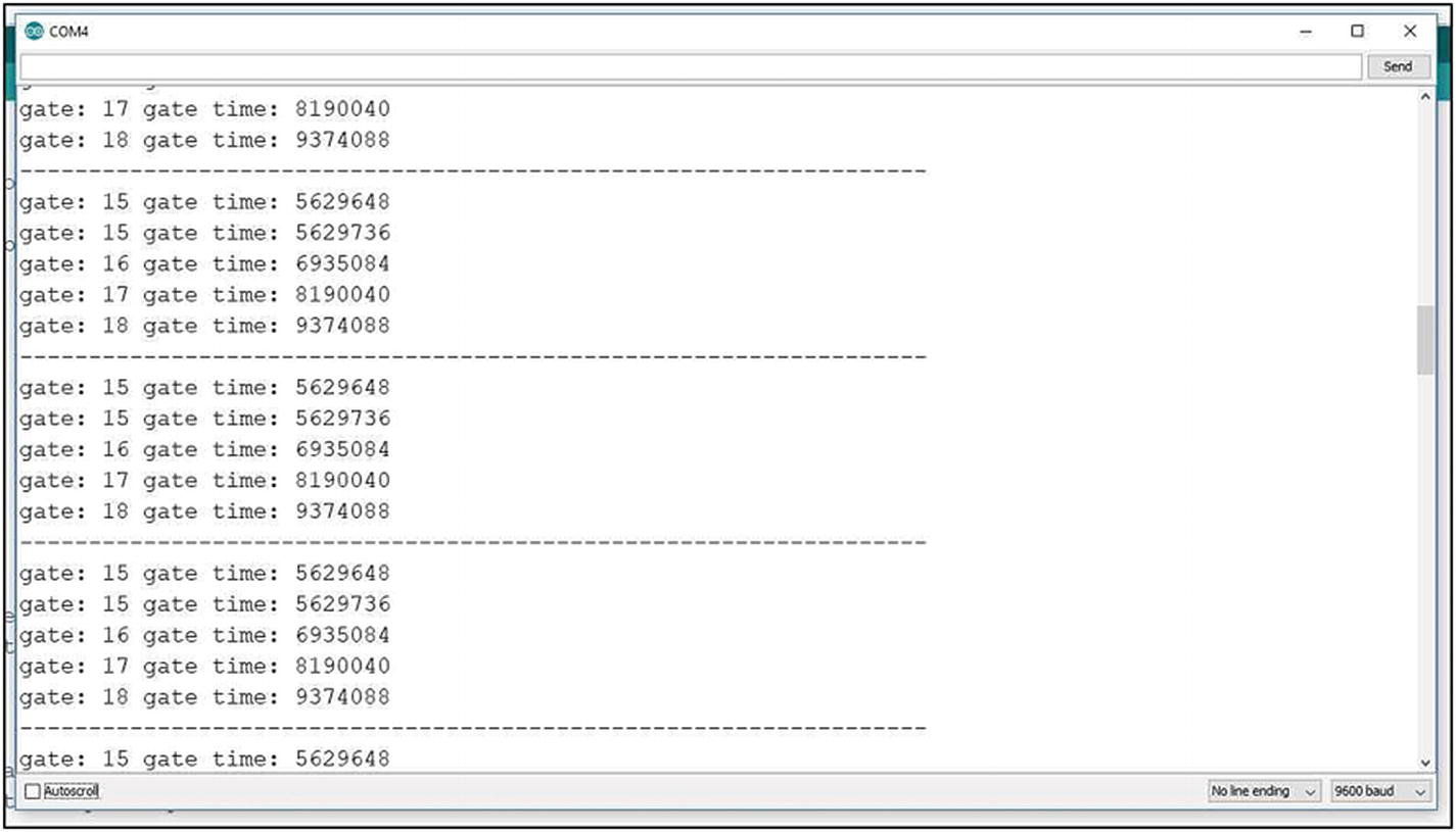
A five-photogate blockage timing record
An event requiring an interrupt is determined by the requirements of the experiment at hand. Figure 1-17 records the times of a photogate passage and four bounce-free button pushes.
Code Listings
A Utility Program to Read the Character String Arriving at the RPi–Python Serial Port
Read the Serial Port Character String and Slice Out the Numerical Symbols for Conversion to Numerical Values
Modified Code for matplotlib Strip-Chart Recorder Plotting of Serial Port Data
Arduino pin interrupt code
Summary
Both the Arduino and Raspberry Pi projects began as educational concepts designed to provide very low-cost introductory hardware support for students to learn computer programming and physical computing.
Both projects have grown far beyond their original educational purpose and are used commercially and industrially and have generated a large online community of amateur and professional researchers and engineers in need of rapid-prototyping capabilities.
Although envisioned in two different countries and brought to market seven years apart, each device is complementary to the other and in combination form an extremely flexible and powerful physical computing and SCADA system.
In Chapter 2, a basic outline is developed for implementing a Python–Arduino SCADA system.