3
Detachable Joints and Fastening Methods

Nomenclature
- A
- effective area of contact surface, mm2
- d
- major diameter, mm
- d 0
- diameter of bolt shank, mm
- d 1
- minor diameter, mm
- d 2
- mean diameter, mm
- F
- external tensile load per bolt, N
- F i
- load carried by individual bolt in a group, N
- F max
- maximum load in a bolt group, N
- F s
- shear load acting on each bolt, N
- F Σ
- total external load, N
- f
- coefficient of friction
- h
- thread height, mm
- i
- the number of contact surface
- K s
- antiskid factor
- k b
- stiffness of the bolt
- k m
- stiffness of the clamped members
- L i
- distance from y‐axis to the bolt axis, mm
- L min
- minimum length of bearing surface, mm
- l
- lead, mm
- M
- overturning moment, N mm
- n
- number of threads, start
- p
- pitch, mm
- Q
- total load in the bolt, N
- Q′ p
- resultant load in the clamped members, N
- Q p
- preload, N
- r i
- radial distance between centroid and ith bolt centre, mm
- S
- safety factor
- S p
- safety factor for crushing
- T
- torque, N mm
- T 1
- frictional torque in the thread, N mm
- T 2
- frictional torque at bearing surface, N mm
- W
- effective section modulus, mm3
- z
- number of bolts in a joint group
- α
- thread angle, °
- β
- helix angle, °
- γ
- lead angle, °
- λ
- deflection, mm
- σ
- tensile stress, MPa
- σ ca
- calculated tensile stress, MPa
- σ p
- bearing stress, MPa
- σ s
- yield strength, MPa
- [σ]
- allowable tensile stress, MPa
- [σ p ]
- allowable bearing stress, MPa
- τ
- shear stress, MPa
- [τ]
- allowable shear stress, MPa
- ϕ v
- equivalent frictional angle, °
3.1 Introduction
3.1.1 Applications, Characteristics and Structures
Machine joints are used to connect two or more components together. They form indispensable parts in machine constructions, as they facilitate manufacturing and assembly, accommodate shipping and handling, permit disassembly for repair, replacement and maintenance. Virtually all machines comprise an assemblage of individual parts, separately manufactured and joined together by various fastening methods [1]. For example, a jumbo jet such as Boeing's 747 uses about 2.5 million fasteners [2].
Machine joints can be broadly classified as detachable and permanent joints. Detachable joints can be disassembled without damaging any element in the connection. Connections using threaded fasteners, keys and splines are typical examples of detachable joints. Permanent joints refer to connections like riveting, welding, bonding (brazing, soldering, adhesive bonding) and so on that cannot be disassembled without damaging elements of the joint.
As joints and connections cause geometrical and material discontinuities, high local stresses and potential failures, the number of joints should be reduced [ 1–4]. As a matter of fact, joints remain the weakest link in a machine and their high safety concern presents an incessant challenge to designers and engineers. It is therefore necessary to have a thorough understanding of performance and careful analysis of joints under all conditions of service, especially in cars, aeroplanes, steam and gas turbines and so on where mechanical reliability and human safety are vital.
This chapter will discuss in detail the analysis and design of conventional standard threaded fasteners. The detachable fastening methods for shaft and hub, as well as permanent connection methods will be introduced in the following chapters.
3.1.2 Selection of Fastening Methods
The selection of fastening methods depends upon many factors. The first is whether the joint is to be permanent or detachable. The selection of permanent joints is mainly due to the consideration of manufacturing and assembly costs; while the selection of detachable joints considers far more factors, including structure, assembly, transportation, maintenance and so on. Normally, permanent joints are less expensive than detachable joints.
Fastening methods use such devices as bolts, screws, nuts, keys, pins, rivets, welds and adhesives for various applications. Typical application scenarios of the individual devices are another consideration. Usually, threaded fasteners, welds, rivets, adhesive bonds are used to connect plates; threaded fasteners and welds can join rods; keys and splines can connect shafts with hubs; pins, setscrews are chosen for retaining shaft‐mounted components; interference fit for mounting rolling contact bearings; couplings and clutches link shafts together [ 1– 4]. In general, the use of threaded fasteners remains the basic and the most widely used fastening method in the design and construction of a machine.
Other considerations include size, thickness, geometries and weight of the components to be joined. And the most important factor is the loading conditions, which greatly influence the strength of joints.
3.2 Screw Threads
3.2.1 Types of Screw Threads
Screw threads are helical ridges formed by cutting or cold forming a groove onto the surface of a cylindrical bar, producing a screw, bolt and stud; or internally in a cylindrical hole, fabricating a nut [5]. Different types of screw threads are classified according to various criteria, such as function, profile, pitch, thread position, directions and starts.
Figure 3.1a is basically the same for both Unified (inch series) and ISO (metric) threads [3], used on screws for fastening. Square, Acme and buttress threads shown from Figure 3.1b–d are power screws. Among them, the square thread has the greatest strength and efficiency, yet is more difficult to fabricate because of the 0° thread angle. Acme and buttress profiles have small thread angles making them easier to manufacture. Acme profile is selected to carry bidirectional loads, while buttress is for unidirectional loading.

Figure 3.1 Typical types of screw threads. (a) Unified and M profile. (b) Square. (c) Acme. (d) Buttress.
Source: Adapted from Juvinall and Marshek, 2011, Figure 10.4, p. 415. Reproduced with permission of John Wiley & Sons, Inc.
For most standard screw threads, at least two pitches are available; that is, coarse series and fine series. Coarse threads are recommended for ordinary applications, especially where rapid assembly or disassembly is required. Fine threads have better capability of resisting loosening from vibrations because of their smaller lead angle. They have a smaller thread depth and larger root diameter that provide higher static tensile strength. Fine threads are used in automobiles, aircraft and other applications that are subject to vibration. Extra‐fine threads may be used for more precise adjustments or thin‐wall tubing applications.
According to the thread position, external threads are the threads on a screw, while internal threads are the threads on a nut or threaded hole. Threaded fasteners work by assembling the matching external and internal threads together.
There are also left‐handed and right‐handed threads, which are based on the direction of helix line. Threads are usually made right‐handed unless otherwise indicated. That is, if the bolt is turned clockwise, the bolt advances towards the nut.
Screws can be multiple‐threaded by having two or more threads cut beside each other. Multiple threads have the advantages of smaller thread height and increased lead for fast advancement of nuts. Standardized products such as screws, bolts and nuts all have single threads.
3.2.2 Standards and Terminology
The geometry and terminology of screw threads, illustrated in Figure 3.2, is explained as follows:
- 1. Major (or nominal) diameter d: the largest diameter of a screw thread.
- 2. Minor (or root) diameter d 1: the smallest diameter of a screw thread.
- 3. Pitch diameter (or mean diameter) d 2: the diameter where the width of the thread and groove are equal.
- 4. Pitch p: the axial distance between corresponding points on adjacent threads. The pitch in Unified Inch standard is the reciprocal of the number of threads per inch.
- 5. Lead l: axial distance the mating thread (or nut) will advance in one revolution. For a single‐threaded screw l = p; for a multiple‐threaded screw, l = np, while n is the number of threads.
- 6. Thread height h: the radial distance between the major diameter and minor diameter.
- 7. Thread angle α: the angle between the flanks of adjacent threads measured in an axial plane.
- 8. Lead angle γ: the angle between the perpendicular of the screw axis and the rise of the thread, tanγ = l/πd 2.
- 9. Helix angle β: the angle between the screw axis and the rise of the thread.
- 10. Starts n: the number of threads.

Figure 3.2 Geometry and terminology of external screw thread.
Two identification codes are used to identify screw threads; that is, Unified and ISO. Most fasteners in the US, Canada and the UK use the Unified Inch profile according to the ANSI standard, while Europe and China use the ISO (metric) standard.
Two Unified thread series are in common use, that is, UN and UNR, with the difference that a root radius is used in the UNR series. Unified threads are specified by a short‐hand designation in the sequence of nominal major diameter, the number of threads per inch, thread series and tolerance classes. For example, 1/4‐28UNF‐2A identifies an external thread with a nominal major diameter of 1/4 in., unified fine thread series with 28 threads per in., class 2 fit and right‐handed. Detailed dimensions of coarse thread UNC (Unified National Coarse) and fine thread UNF (Unified National Fine) within the UN series can be found in reference [6].
Metric threads are designated by M (‘for metric’) followed by a major diameter and a pitch in millimetres separated by the symbol ‘×’. A right‐handed thread is assumed unless the designation is followed by ‐LH. Thus, M24 × l.5‐LH is a left‐handed thread with a nominal major diameter of 24 mm and a pitch of 1.5 mm. Standard sizes for selected metric threads are given in Table 3.1.
3.3 Threaded Fastening Methods
3.3.1 Types of Threaded Fastening Methods
Threaded fastenings are the basic assembly method in the design and construction of machines. Threaded fasteners join the matching external and internal threads together by the following typical methods.
- 1. Bolted joints
A bolted joint is designed to let a bolt to pass through holes in mating members and secured by tightening a nut from the opposite end of the bolt [2]. Both ordinary bolted joints (Figure 3.3a) and precision bolted joints (Figure 3.3b) are available. Ordinary bolted joints have bolt shanks inserted in the holes with a clearance, while precision bolted joints have bolt shanks fitting into reamed holes without appreciable clearance. Both of them are applied to join relative thin members by using thorough holes.
- 2. Stud joints
A stud is a stationary bolt attached permanently to one of the members to be joined. The mating member is then placed over the stud and a nut is tightened to clamp the members together, as indicated in Figure 3.3c. A stud joint applies when one of jointed components is too thick to drill a body size hole. The joint can be disassembled frequently by removing the nut and washer, without damaging the threaded member.
- 3. Cap screw joints
A cap screw fastening is designed to let a cap screw to insert through a hole in one member to be joined and into a threaded hole in the mating member [2], as shown in Figure 3.3d. The threaded hole may be formed by tapping or by the cap screw itself. It applies when one of jointed components is too thick to drill a body size hole or the space is too small to mount a nut. Such joints cannot be disassembled frequently.
- 4. Setscrew joints
A headless setscrew is designed to be inserted into a tapped hole to bear directly on the mating element, as shown in Figure 3.3e. Setscrews depend on compression to develop clamping force to lock components into place. They are inexpensive and adequate for light service. However, they should not be used in vibration applications where loosening would impose a safety hazard.

Figure 3.3 Types of threaded fastening methods.
Many other types of threaded fastening methods are available in various applications, for example anchor bolts to fix machines on the foundation, or eyebolts to lift machine components and so on.
3.3.2 Threaded Fasteners
Threaded fasteners are standard and commercially available products used to connect two or more elements. The possibility for different combinations of material grades, thread dimensions, tolerance grade and manufacturing methods forms a large variety of threaded fasteners. These combinations are considered in American National Standards, British Standards, Chinese Standards, ISO Standards and so on [ 6,7]. The use of standard products offers the advantages of interchangeability and low cost, and guarantees they are indispensable devices throughout the industrialized world.
Threaded fasteners perform the function of locating, clamping, adjusting and transmitting force from one machine element to another [5]. They form a big family, including bolts, studs, machine screws, setscrews, nuts and so on. A bolt is a headed, threaded fastener designed to connect two unthreaded components with the aid of a nut, as shown in Figure 3.3a, b. Bolts have standard thread length and total length. Various standard head styles and thread configurations are readily available. A stud is a headless fastener threaded on both ends and is usually screwed permanently into a tapped hole (Figure 3.3c).
A screw (machine screw or cap screw) is a headed, threaded fastener designed for the assembly of two components, one of which contains its own internal thread as shown in Figure 3.3d. Screws generally have several head (see Figure 3.4) and tip configurations, and are tightened by a screwdriver into tapped holes.

Figure 3.4 Typical cap screw heads. (a) Slotted round‐head screw. (b) Hex‐head cap screw. (c) Phillips round‐head screw. (d) Hexagonal socket‐head screw. (e) Slotted flat‐head screw. (f) Slotted oval‐head screw.
Headless setscrews are designed to bear directly on the mating part by being inserted into tapped holes to prevent relative motion (see Figure 3.3e). Figure 3.5 shows several types of points of setscrew. The setscrew transmits torque by the friction between the point and the mating part or by the resistance of the material in shear.

Figure 3.5 Typical points of setscrews: (a) cone point, (b) cup point, (c) flat point and (d) full‐dog point.
Different types of nuts and locknuts are available. The purpose of using nuts is to make the threads deflect to distribute the load of bolt more evenly to the nut. The material of nut must be selected carefully to match that of the bolt. Figure 3.3a–c shows common hexagonal nuts. Jam nuts have reduced thickness and usually used together with hexagonal nuts for loosing prevention. Locknuts and lock washers are used for locating the element axially on a shaft, as shown in Figure 10.8b.
Washers are used under a bolt head or under both a bolt head and nut. The basic type of washer is a plain flat washer, which distributes clamping forces over a wide area. When loaded, a split helical lock washer will deform axially, generating axial forces on the fastener to prevent loosing, as used in Figure 3.3a, d.
This book only presents typical types of threaded fasteners. Detailed information for almost endless threaded fasteners can be found in various standards, design handbooks [ 6, 7] and on the Internet.
3.3.3 Tightening Torque and Preloading
The purpose of a bolt fastening is to clamp two or more elements together. For most applications, a bolted joint is tightened during assembly before it starts to carry operating loads. While tightening, the bolt head is usually held stationary and the nut is twisted. The nut moves along the screw and, when resistance is encountered, axial force will generate in the thread [5]. This axial force is called preload, initial tension or pretension. It is this force that clamps two or more members together. The consequence of tightening process is that the bolt is preloaded in tension, while the clamped elements in compression.
The value of preload must be properly controlled to enhance resistance to potential fastener loosening and fatigue failure. Too small a preload may cause leakage, while too high a preload may twist off bolts or screws. The maximum preload is taken to be 75% of the proof load [ 2, 4], which is the product of the proof strength times the tensile stress area of the bolt or screw.
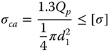
The required preload can be controlled by tightening torque T, which can be estimated by [8]
where T 1 and T 2 are frictional torque in the thread and at the bearing surface, respectively. Q p is the preload and d is the major diameter of the thread.
In practice, tightening torques are controlled or monitored approximately by a built‐in dial that indicates the torque in a torque wrench. A more accurate approach to determine the value of preload is by bolt elongation measurement, especially for high reliability design.
3.3.4 Fastener Loosening and Locking
Twisting a nut stretches the bolt and produces clamping force within the connected members. However, the initial tension or preload may be lost gradually due to wear, creep, impact, vibration or corrosion during operation. When the initial preload is lost, the in‐service threaded fasteners will loosen, causing separation of the connected members and resulting in malfunctioning of machines. Periodically retightening is a convenient and effective method to re‐establish a proper preload to prevent excessive loosening.
Several methods are available to restrain a nut from becoming loose on a bolt. The first is by increasing supplementary friction, such as using jam nuts or double nuts in Figure 3.6a, or using a split helical lock washer in Figure 3.3a. The second is by using special devices, as illustrated in Figure 3.6b, by inserting a split cotter pin through the cross‐hole drilled in bolt passing through the slotted nut and in Figure 10.8b by locknut and lock washer. The third is to permanently damage screw threads by brazing, soldering, punching or gluing.

Figure 3.6 Locking devices.
3.4 Force Analysis of Multiply Bolted Joints
In common practice, a group of bolts are placed in a specified pattern to form a multiply bolted joint to carry various external loads, as illustrated in Figure 3.7. The external loads are shared among these bolts. Since the materials, dimensions, preloads and so on are usually identical for each bolt in a multiply bolted joint, it is therefore important to identify the bolt that carries the largest load and ensure its safety. This section will analyse force distribution among bolts within a group under typical loading conditions.

Figure 3.7 Loads carried by multiply bolted joints.
3.4.1 Multiply Bolted Joints Subjected to Symmetric Transverse Loads
If a transverse load is applied symmetrically to a multiply bolted joint, as illustrated in Figure 3.8a, it is usually acceptable to assume that the loads are uniformly distributed among all the bolts. The transverse load can be carried by two kinds of bolted joints, that is, ordinary bolted joints or precision bolted joints.

Figure 3.8 Multiply bolted joints subjected to symmetric transverse loads.
In an ordinary bolted joint there is a clearance between the hole and bolt, as shown Figure 3.8b. The transverse load is thus carried by friction between the joint interfaces and ensured by the clamping action of the bolt. Assuming each bolt has the same preload, then we have
Therefore

where
- K s
- – antiskid factor to account for reliability, usually select as K s = l.1–1.3;
- f
- – coefficient of friction. For dry cast iron and steel machined surface, select f = 0.1–0.2; For coarse surface without machining, select f = 0.3–0.45.
In a precision bolted joint, the bolt provides precise alignment of mating members, that is, the diameter of the hole and bolt shank are exactly the same, as shown in Figure 3.8c. The transverse load is thus carried by shearing and bearing of the bolt shank. Assuming each bolt is subjected to an identical load, the load each bolt carries is then

3.4.2 Multiply Bolted Joints Subjected to a Torque
When a multiply bolted joint carries a torque in a jointed plane, the connected members tend to rotate around the centroid of bolt group. Both ordinary bolted joints and precision bolted joints can be used in such a situation to carry the torque.
When using ordinary bolted joints, the torque is carried by frictional force between the connected members, as shown in Figure 3.9a. Assuming each bolt carries the same preload, from the equilibrium condition of torque, we have

Figure 3.9 Multiply bolted joints subjected to a torque.
Therefore,

where r i is radial distance from the centroid to the centre of ith bolt.
When using precision bolted joints, the torque is carried by shearing and bearing of bolt shank, as shown in Figure 3.9b. Assuming each bolt has the same stiffness, the shear load each bolt subjected to is proportional to the distance from the centroid to the centre of each bolt. It thus gives

The force taken by each bolt depends upon its radial distance from the centroid; that is, the bolt farthest from the centroid takes the greatest load, while the nearest bolt takes the smallest load. From the equilibrium condition, we have
Combining these two equations, the maximum load a bolt subjected to is

3.4.3 Multiply Bolted Joints Subjected to a Symmetric Axial Load
If a total external axial load F Σ is symmetrically applied to a multiply bolted joint, as illustrated in Figure 3.10, it is usually acceptable to assume that the external load is uniformly distributed among all the bolts. Therefore, the external load each bolt subjected to is


Figure 3.10 Multiply bolted joints subjected to a symmetric tension load.
The total load a preloaded bolt carries will be discussed in detail in Section 3.5.3.3.
3.4.4 Multiply Bolted Joints Subjected to an Overturning Moment
Figure 3.11a shows an overturning moment M acting on a multiply bolted joint. Assume the overturning moment M is in the symmetrical plane XOZ, vertical to the jointed plane. Before the bolted joint takes the overturning moment, all the bolts are preloaded and elongated equally and the foundation or the connected member is compressed uniformly. When the overturning moment M is applied to the multiply bolted joint, the bolts on the left side of y‐axis will be stretched further and the foundation will be relaxed; while on the right side, the bolts will be pressed, and the foundation will be compressed further. According to the equilibrium condition, the total moment generated by the load in each bolt F i should be balance with the external moment M. Therefore

Figure 3.11 Multiply bolted joints subjected to an overturning moment.
The force taken by each bolt depends on the distance from its centre to the y‐axis; that is, the bolt farthest from the y‐axis takes the largest load, while the nearest bolt takes the smallest load. We can therefore write

Solving these equations simultaneously, the external force on the most heavily loaded bolt in the group is

For the connected member, the contact surfaces must be free from crushing on the right and free from separation on the left, satisfying the following equations, respectively.

and

where W is effective section modulus of the contact surface and A is the effective area of the contact surface.
In real engineering practice, the total load a multiply bolted joint is subjected to is usually the combination of the previously discussed cases. The basic approach to obtain the load on each bolt is decomposition and superposition. The complex external load is first decomposed into simple loading cases and the load each bolt carries under each simple loading condition is obtained by previous analyses. The vector sum of these results forms the total load a bolt carries. Since all the bolts within a group are identical, we only need to consider the bolt carries the maximum load. When the bolt that carries the maximum load is identified, the strength of bolt can be determined by the methods to be introduced next.
3.5 Strength Analysis
3.5.1 Potential Failure Modes
According to the previous force analysis, it is found that although multiply bolted joints can carry various external loads, each individual bolt actually carries either tension loads or shear loads. Correspondingly, they are termed tension bolts or shear bolts.
A tension bolt carries external axial loads, preload or the combination of both. Potential failure modes for a tension bolt may be elastic or plastic deformation. Machinery constantly operate dynamically; accordingly, tension bolts usually have a small dynamic load superimposed on a much larger static preload. The fluctuating load will cause fatigue fracture failure in fasteners. A shear bolt is subjected to a transverse shearing load. The potential failure modes may be the crushing or shearing of bolt shanks.
Other failure modes can also be observed depending on operating conditions, for example, fretting fatigue due to small amplitude cyclic relative motions at the interface, corrosion fatigue in corrosive environments, creep and thermal relaxation at elevated temperatures in jet engines and nuclear reactors, wear in movable joints and so on.
Statistically, the distribution of typical bolt failure is about 15% at the fillet under head, 20% at the end of thread and 65% at the first thread engaged in a nut [9,10]. These are the locations of high stress concentration.
3.5.2 Strength Analysis for Shear Bolts
Shear bolts, usually used in precision bolted joints, are used to carry transverse loads, as illustrated in Figure 3.8c. Since there is no clearance between the bolt shank and the inner surface of hole, the transverse load is carried by bearing between the shank and cylindrical hole and shear at the shank cross section. Assume that the bearing stress is uniformly distributed over the projected contact area of the bolt shank, the crushing strength is then [11]

The shearing strength at the bolt shank cross section is calculated by

3.5.3 Strength Analysis for Tension Bolts
Tension bolts, usually used in ordinary bolted joints, are assembled with or without pretension. Tension bolts with pretension are capable of carrying not only static and dynamic axial loads but also transverse loads; while tension bolts without pretension carry axial loads only.
3.5.3.1 Tension Bolts Subjected to Axial Loads Only
A tension bolt without tightening is capable of carrying static axial loads only. One of its limited applications is in a hoisting hook. The strength of bolt is calculated by

3.5.3.2 Preloaded Tension Bolts Subjected to Transverse Loads
The purpose of using bolts is to clamp two or more elements together. The clamping load stretches the bolt by twisting the nut until the bolt elongates approaching the proof strength. If the nut does not loosen, this bolt tension remains as the preload. The tensile stress caused by the initial preload Q p on the bolt is

The torsional shear stress due to frictional torque in the thread T 1 generated by tightening can be obtained from [8]

Selecting the average value of γ, φ v and d 2 for the commonly used bolts within the range of M10–M64, we have [8]

Since the bolt is subjected to both tensile and shear stresses, the equivalent stress is calculated by the maximum distortion energy theory as
Therefore, the calculated tensile stress due to preloading is

Although tightening torque generates combined tensile and shear stresses in a bolt, we can simplify the analysis by calculate the tensile stress only, while increasing the value by 30% to account for the effect of torsional shear stress.
When preloaded bolts carry transverse loads, friction between joint members resists the external transverse loads. The bolt is subjected to preload only, not affected by the transverse loads. The magnitude of preload is determined by Eq. (3.2), and the strength for a preloaded tension bolt subjected to a transverse load is thus
3.5.3.3 Preloaded Tension Bolts Subjected to Combined Preload and Static Axial Loads
When an external static axial load is applied to a preloaded tension bolt, the bolt is subjected to a combined preload and static axial loads. As shown in Figure 3.12, before the joint carries an external load, the tightening torque initially applied to the nut or on the head of bolt produce a preload load Q p in the bolt. The preload Q p exerts tension on the bolt and stretch the bolt by a deflection λ b ; while the same amount of force Q p on the clamped members compress the members by a deflection λ m . The stiffness of a bolt is the ratio of the applied force to the corresponding deflection, expressed as


Figure 3.12 Force‐deflection relationships of bolt and connected members.
Similarly, the stiffness of the connected members is

When an external static axial load F is applied to a preloaded tension bolt, the bolt will stretch further by Δλ. Thus, the total deflection of the bolt is λ b + Δλ and the total deflection on the clamped members is λ m −Δλ. The initial preload and the applied axial load add to give resultant forces of Q and Q′ p on the bolt and the clamped members, respectively. Thus, only part of the applied force is carried by the bolt. The amount is dependent on the relative stiffness of the bolt and the clamped members.
According to the force equilibrium and force‐deflection relationships, the forces in the bolt and in the clamped members are calculated by
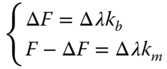
From these equations, we then have

Therefore, the total load in the bolt is

The total load in the bolt includes the initial preload due to tightening, and a partial of subsequently applied operating force, which tends to separate the clamped members. And the resultant load in the clamped members is

where ![]() is the relative stiffness of the joint. Since gaskets are usually inserted at the interface between bolted members, the relative stiffness depends on the material of gaskets. For a metal gasket, it is approximately 0.2–0.3; for leather 0.7; for asbestos, 0.8 and for rubber, 0.9.
is the relative stiffness of the joint. Since gaskets are usually inserted at the interface between bolted members, the relative stiffness depends on the material of gaskets. For a metal gasket, it is approximately 0.2–0.3; for leather 0.7; for asbestos, 0.8 and for rubber, 0.9.
The total load in the bolt depends greatly on the relative stiffness. If k b > k m , we have Q ≈ Q p + F; while for k b < k m , we have Q ≈ Q p . Therefore, when a bolted joint carries a relatively large load, high stiffness gaskets should be used.
To prevent the separation of joint, the resultant load in the clamped members Q′ p should be greater than zero, that is,
For ordinary bolted joints subjected to a stable load, select Q′ p = (0.2–0.6) F; for ordinary bolted joints subjected to a variable load, Q′ p = (0.6–1.0) F; for a sealing case, Q′ p = (1.5–1.8) F and for anchor bolt joints, Q′ p ≥ F [8].
The static strength of a preloaded bolt subjected to a combined preload and static axial loads is then

3.5.3.4 Preloaded Tension Bolts Subjected to Combined Preload and Variable Axial Loads
When a preloaded tension bolt is subjected to a variable load fluctuating between zero and an upper extreme F, the total load in a bolt varies from Q p to Q, as indicated in Figure 3.13. The alternating stress experienced by the bolt is then


Figure 3.13 Preloaded tension bolt subjected to combined preload and variable axial load.
Therefore, the minimum value of stress keeps constant and the amplitude of stress is calculated by

From the endurance limit diagram and methods introduced in Chapter 2, the fatigue safety factor can be obtained by duplicating Eq. (2.30) as

If the design is not satisfactory, additional bolts and/or a different sized bolt may be called for.
3.5.4 Measures to Improve Fatigue Strength of Bolted Joints
The fatigue strength of a multiply bolted joint depends on the strength of each individual bolt in the group. Many factors affect bolt fatigue strength, including the stress amplitude, the distribution of load among thread teeth, stress concentration, mechanical properties and processing methods. The following will analyse typical factors affecting fatigue strength and propose measures for improvement.
- 1. Reduce cyclic stress amplitudes on the bolt
When the minimum stress keeps constant, stress amplitude greatly affects fatigue strength [12]. For a preloaded bolt, when the external operating load varies between 0 and F, the total load acting on the bolt varies from Q p to Q, as illustrated in Figure 3.13. The load variation in the bolt will reduce if the stiffness of the bolt is reduced or the stiffness of the clamped members is increased, as can be noticed from Eq. (3.18).
However, reducing the stiffness of the bolt or increasing the stiffness of the clamped members under a constant preload will inevitably reduce the resultant load in the clamped members and consequently weaken the sealing effect. Therefore, it is preferable to increase the preload simultaneously so that the resultant load in the clamped members does not change too much. While increasing the preload, the preload must be controlled to prevent twisting off the bolt while tightening.
- 2. Reduce stress concentration
Stress concentration is an important factor affecting fatigue strength. Stress concentration often happens where geometrical discontinuity appears. For a bolt, the screw end, the connection of bolt head and shank and the area where the cross‐section changes are the places stresses concentrate. Proper modification of standard bolts, like increased fillet radius under the head, can effectively reduce stress concentration.
- 3. Adopt proper manufacturing methods
Rolled threads are preferred compared with cut or grounded threads, as rolling processes cause work hardening of materials and generate a favourable grain structure and compressive residual stresses, which benefit the improvement of fatigue strength. Furthermore, proper heat treatment like nitriding and shot peening will also increase fatigue strength of bolts.
3.6 Design of Bolted Joints
3.6.1 Introduction
More often than not, multiply bolted joints involve several bolts placed in a specified pattern to improve strength and stability of a connection. The design of multiply bolted joints consists of two tasks: one is to decide the number of bolts in a pattern and their layout; the other is to specify the dimension and material of the fasteners. The former requires structural design, while the latter needs force and strength analysis.
3.6.2 Materials and Allowable Stresses
A wide variety of materials are used for threaded fasteners. The selection of materials for threaded fasteners is normally based on the requirements of strength, weight, corrosion resistance, magnetic properties, life expectancy and costs. The most widely used materials are carbon steels and alloy steels. Stainless steels and nickel‐based superalloys, such as Inconel and Hastelloy, are used for fasteners working in corrosive or high temperature environments. Aluminium, bronze and brass threaded fasteners are used for applications where corrosion resistance and good thermal and electrical conductivity are required. Nylon and plastics are both suitable for applications with more economical considerations than strength requirements.
The strength of steels for bolts and screws is used to determine property classes. Three strength ratings are involved; namely, tensile strength, yield strength and proof strength. The proof strength is defined as the stress at which the bolt or the screw would undergo permanent deformation, usually 90–95% of the yield strength [4]. The value depends on the material, heat treatment and other factors.
Recommended materials for property class 4.6–5.8 are low or medium carbon steels; for property class 8.8–9.8, low carbon alloy steel and medium carbon steel, heat treated by quenching and tempering; for property class 10.9, low and medium carbon alloy steels by quenching and tempering and for property class 12.9, alloy steel by quenching and tempering [ 2, 7].
Table 3.2 details mechanical properties of different property classes for metric fasteners. Property classes are identified by a numerical code system ranging from 4.6 to 12.9 to represent the strength. The numeral before the decimal point is the tensile strength divided by 100 (σ b /100), while the numeral following the decimal point is 10 times the ratio of yield strength to tensile strength (10σ s /σ b ). For example, property class 4.6 implies that the tensile strength is 400 MPa, and the ratio of yield strength to tensile strength is 0.6. Nuts are graded to mate with their corresponding class bolts.
Table 3.2 Mechanical properties of fasteners – bolts, screws and studs.
Source: Budynas and Nisbett, 2011, Table 8.11, p. 435. Reproduced with permission of McGraw‐Hill.
| Property class | Size range, inclusive | Minimum proof strength, MPa | Minimum tensile strength, MPa | Minimum Yield strength, MPa | Material | Head Marking |
| 4.6 | M5–M36 | 225 | 400 | 240 | Low or medium carbon |

|
| 4.8 | M1.6–M16 | 310 | 420 | 340 | Low or medium carbon |

|
| 5.8 | M5–M24 | 380 | 520 | 420 | Low or medium carbon |

|
| 8.8 | M16–M36 | 600 | 830 | 660 | Medium carbon, Q&T |

|
| 9.8 | M1.6–M16 | 650 | 900 | 720 | Medium carbon, Q&T |

|
| 10.9 | M5–M36 | 830 | 1040 | 940 | Low‐carbon martensite, Q&T |

|
| 12.9 | M1.6–M36 | 970 | 1220 | 1100 | Alloy, Q&T |

|
The American Society for Testing Materials (ASTM), the Society of Automotive Engineers (SAE) and the Standardization Administration of China (SAC) have established similar standard specifications for materials and strength levels for threaded fasteners. Designers can refer to relevant standards or design handbooks while designing [ 6, 7,13].
The allowable tensile stress is decided by
where yield strength σ s is selected from Table 3.2, and safety factor S is selected as 4–1.3 for M6–M60 carbon steel bolts and 5–2.5 for M6–M60 alloy steel bolts, respectively. When preloaded bolted connections carry variable loads, safety factors may be twice the values of those for static loading [7].
The allowable bearing stress is calculated by

where the safety factor for crushing S p is 1.25 for steel and 2.5 for cast iron [8].
The allowable shear stress is calculated by [8]
3.6.3 Design Criteria
For a tension bolt that is subjected to a preload, or a static axial load or a combination of both, it must meet the strength requirement by σ ≤ [σ], as expressed in Eqs. (3.12, 3.15, 3.21), depending on the loading conditions. When a tension bolt carries a fluctuating load, fatigue strength S ≤ [S] should also be guaranteed, as expressed by Eq. (2.30). Besides, to ensure safe and proper functioning of bolted joints, the preload induced by bolt tightening must be great enough to prevent joint separation during operation.
The design criterion for a shear bolt is to guarantee crushing strength σ p ≤ [σ p ] expressed by Eq. (3.10), and shear strength τ ≤ [τ] by Eq. (3.11).
3.6.4 Design Procedure and Guidelines
Although multiply bolted joints usually work together in practical engineering, the failure of a single fastener in a group can be destructive or even catastrophic. Designers must select and decide the type, material, property class and size of standard fasteners to ensure all of them will most adequately suit the application. The following provides the procedure and guidelines for bolted joint design:
- 1. Decide the pattern of bolt layout and the number of bolts in the group. Ideally, it is better to ensure each bolt within the group is uniformly loaded, or to minimize the maximum load a bolt carries.
- 2. Analyse operating loads on the bolted joint. Dissolve the loads into simple load conditions; that is, tensile loads, shear loads, torques and moments.
- 3. Determine the load each bolt subjected to according to the bolted joint type (ordinary or precision bolted joints), assembly condition (with preload or without preload) and loading condition (transverse or axial loading, static or dynamic loading). The basic approach is first to determine the forces that act on each bolt by each applied load separately. Then, superpose the forces vectorially to identify the bolt that carries the greatest load in the group.
- 4. Determine the critical section dimension, usually the minor diameter d 1, according to the design criteria.
- 5. Decide the size of bolts, nuts, washers and so on according to design handbooks and manufacturers' catalogues.
3.6.5 Structural Design
Structural design determines bolt layout pattern and bolt number, following these guidelines:
- 1. The bolt layout is usually designed as a simple, symmetric geometry, such as a square, rectangle or circle.
- 2. Select an even number of bolts in a group to facilitate manufacture and to ensure equal loading. Each bolt should have the same size (both diameter and length), thread series (coarse or fine), material and property class.
- 3. Ensure rational arrangement of bolts. Sufficient room should be provided for a wrench between adjacent bolts or between the bolt and the edge of jointed members, as indicated in Figure 3.14a.
- 4. The coarse surface to be joined by a bolt should be machined, as shown in Figure 3.14b, to avoid additional induced bending stress during operation.

Figure 3.14 Examples of structural design considerations.
3.6.6 Design Cases
References
- 1 Collins, J.A. (2002). Mechanical Design of Machine Elements and Machines: A Failure Prevention Perspective, 1e. New York, NY: Wiley.
- 2 Budynas, R.G. and Nisbett, J.K. (2011). Shigley's Mechanical Engineering Design, 9e. New York, NY: McGraw‐Hill.
- 3 Juvinall, R.C. and Marshek, K.M. (2011). Fundamentals of Machine Component Design, 5e. New York, NY: Wiley.
- 4 Mott, R.L. (2003). Machine Elements in Mechanical Design, 4e. Prentice Hall.
- 5 Hindhede, U., Zimmerman, J.R., Hopkins, R.B. et al. (1983). Machine Design Fundamentals: A Practical Approach. New York, NY: Wiley.
- 6 Oberg, E. (2012). Machinery's Handbook, 29e. New York, NY: Industrial Press.
- 7 Wen, B.C. (2015). Machine Design Handbook, 5e, vol. 2. Beijing: China Machine Press.
- 8 Pu, L.G. and Ji, M.G. (2006). Mechanical Design, 8e. Beijing: Higher Education Press.
- 9 Xu, Z.Y. and Qiu, X.H. (1986). Machine Elements, 2e. Beijing: Higher Education Press.
- 10 Pilkey, W.D. (1997). Peterson's Stress‐Concentration Factors, 2e. New York, NY: Wiley.
- 11 Gere, J.M. and Timoshenko, S.P. (1996). Mechanics of Materials, 4e. CL Engineering.
- 12 Parker, A.P. (1981). Mechanics of Fracture and Fatigue: An Introduction. London: E&FN Spon.
- 13 Mechanical properties of fasteners – Bolts, screws and studs. GB/T 3098.1‐2010, Standardization Administration of the People's Republic of China, Beijing, 2011.
Problems
Review Questions
- 1 Why is preloading important for a bolted connection? How should one control the applied preload?
- 2 Why is loosening prevention important for a bolted connection? Give examples to describe measures to resist loosening.
- 3 A rigid coupling uses property class 5.8 ordinary bolted joints to transmit torque T 1. Currently, the coupling is required to transmit a higher torque T 2, but the number of bolts and their diameters cannot be changed. Propose three methods for the coupling to transmit a higher torque T 2.
- 4 Please discuss the differences and relations between the load carried by a bolt and the load carried by a multiply bolted joint.
- 5 How could one improve the static strength and fatigue strength of a bolted connection?
Objective Questions
- 1 Two components are to be connected by bolts. One of components is relatively thick and the connection is disassembled frequently. Which of the following is the best choice___________?
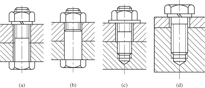
Figure P3.1 Illustration for Objective Question 1. - 2 A preloaded ordinary bolted joint carries axial loads. The preload is Q
p
, the external load is F. The total load the bolt carries is ___________.
- = Q p + F
- <Q p + F
- >Q p + F
- = Q p + F/2
- 3 A preloaded tension bolt is subjected to a variable axial load. Which of the following measures can improve the fatigue strength of the bolt? ___________.
- Increasing the stiffness of the bolt k b and reducing the stiffness of the connected member k m .
- Reducing the stiffness of the bolt k b and increasing the stiffness of the connected member k m .
- Increasing the stiffness of the bolt k b and the stiffness of the connected member k m .
- Reducing the stiffness of the bolt k b and the stiffness of the connected member k m .
- 4 The dimension of the mating nut is selected according to which parameter of the bolt? ________
- d
- d 2
- d 1
- d/p
- 5 When multiply bolted joints carry a transverse load or a torque, the load the bolt is subjected to ______.

Figure P3.2 Illustration for Objective Question 4. - must be a shear load
- must be a tensile load
- could be either a shear load or a tensile load
- both a shear load and a tensile load
Calculation Questions
- 1 A preloaded bolt carries a fluctuating axial load varying from 0 to F. Assuming the criterial area of the bolt is A c , the stiffness of the bolt and the connected member are k b and k m , respectively. Decide on the stress amplitude.
- 2 A flange is attached to a pressurized cylinder by 16 identical bolts. The fluid pressure is cycled from 0 to 1.2 MPa. Let D = 500 mm, the resultant load on the clamped members must be kept as Q′
p
= 1.5F. The allowable stress of bolt material is [σ] = 160 MPa. Determine the size of the bolts.

Figure P3.3 Illustration for Calculation Question 2. - 3 A flange and pressure vessel is connected by 12 M16 (d
1 = 13.6 mm) bolts. The inner diameter of the pressure vessel is D = 250 mm. The allowable stress of the bolt is [σ] = 120 N mm−2. The resultant load on the connected member is Q'
p
= 1.5F (F is the operating load). Decide on the maximum pressure the bolted joint can carry.

Figure P3.4 Illustration for Calculation Question 3. - 4 1. 2. Two half couplings are connected by eight M16 bolts distributed around the bolt circle with a diameter of D = 130 mm. The total length of the bolt is 70 mm, including the screw length of 28 mm. The shank diameter is d
0 = 17 mm. The detailed dimensions of structure are shown in Figure P3.5, where d
1 = 55 mm, L
1 = L
2 = 100 mm and b
1 = b
2 = 25 mm. The two half couplings are made of grey iron HT200, with the allowable bearing stress as [σ
p1
] = 100 MPa. The bolts are made of low carbon steel Q235, with the allowable shear stress [τ] = 90 MPa, allowable bearing stress [σ
p2
] = 300 MPa and allowable tensile stress [σ] = 150 MPa.
- 1. Decide the maximum torque that can be transmitted by the coupling;
- 2. Assuming the coefficient of friction is f = 0.15 and antiskid factor k s = 1.2, if ordinary bolted joints are selected to transmit the same amount of torque, decide on the required minor bolt diameter.

Figure P3.5 Illustration for Calculation Question 4.
Design Problems
- 1 Compare the three design layouts in Figure P3.6 using precision bolted joints, where L = 200 mm and a = 50 mm.

Figure P3.6 Illustration for Design Problem 1.
Structure Design Problems
- 1 Correct the mistakes in Figure P3.7.

Figure P3.7 Illustration for Structure Design Problem 1. - 2 Figure P3.8 shows a cap screw joint. Correct the mistakes in the figure by drawing a new one.

Figure P3.8 Illustration for Structure Design Problem 2. - 3 Draw a setscrew in Figure P3.9 to connect the hub with the shaft.

Figure P3.9 Illustration for Structure Design Problem 3.
CAD (Computer‐Aided Design) Problems
- 1 Write a flow chart for a bolt design process.
- 2 Design an interface similar to Figure P3.10, and complete the Example Problem 3.2.

Figure P3.10 Illustration for Illustration for CAD Problem 2.