
20. Developing Android 3D Graphics Applications
![]()
The world around us is not two-dimensional but rich with depth. Although Android device displays are flat surfaces, presenting games and applications with visual depth has long been a way to enhance and add realism to them. For this purpose, developers can use the OpenGL ES and RenderScript 3D graphic frameworks provided in the Android SDK.
Working with OpenGL ES
Before 1992, Silicon Graphics (SGI) had a proprietary graphics standard called Integrated Raster Imaging System Graphics Library (IRIS GL) and was known typically as just GL. In 1992, to clean up the code and make GL more maintainable, SGI created OpenGL and set up a consortium of companies to maintain the open standard form of GL. Today, this consortium is known as the nonprofit Khronos Group, with more than 100 member companies. OpenGL ES was developed in the early 2000s to extend this open library to embedded devices. OpenGL ES is a subset of OpenGL. EGL was developed shortly thereafter to provide a common interface layer to native platform graphics.
In the interfaces, OpenGL is simply referred to as GL. This is true for OpenGL ES, as well. In the text of this chapter, GL typically refers to the underlying objects and interfaces in OpenGL to be consistent with the naming conventions in the code. OpenGL ES typically refers to the Android implementation of the OpenGL ES subset of OpenGL. Finally, OpenGL is used in a more generic fashion to refer to the generic concept or library.

This chapter discusses how to use OpenGL ES in the Android SDK. Familiarity with OpenGL concepts can be helpful. This chapter does not teach you OpenGL, but it shows you how to perform a variety of common tasks with OpenGL ES on Android devices. These include configuring EGL (Embedded-System Graphics Library) and GL (Graphics Libraries), drawing objects, animating objects and scenes, lighting a scene, and texturing objects.
 Leveraging OpenGL ES in Android
OpenGL ES is a graphics application programming interface (API) for embedded systems based on the OpenGL desktop standard. It is popular on wireless platforms and is supported on all major mobile phone platforms, including Windows Mobile, Symbian, MeeGo, BREW, Apple iOS, Palm WebOS, and now Android. Android devices support different versions of OpenGL ES depending on the platform version.
Android developers can implement 3D graphics applications that leverage OpenGL ES in two ways:
• The Android SDK provides OpenGL ES functionality in the android.opengl package in conjunction with the Khronos javax.microedition.khronos.opengles and javax.microedition.khronos.egl packages.
• The Android Native Development Kit (NDK) can be used to leverage OpenGL ES 1.1 and 2.0 native libraries for optimum performance.
In this chapter, we focus on how to use the Android SDK to develop OpenGL ES applications. We discuss the Android Native Development Kit in Chapter 21, “Using the Android NDK.”
The Android SDK has support for different versions of OpenGL ES, depending on the API Level or platform version:
• OpenGL ES 1.0 functionality (android.opengl) is fully supported on devices running Android 1.0 (API Level 1) and higher.
• OpenGL ES 1.1 (android.opengl.GLES11) is fully supported by devices running Android 1.6 (API Level 4) and higher.
• OpenGL ES 2.0 (android.opengl.GLES20) is fully supported by devices running Android 2.2 (API Level 8) and higher.
Ensuring Device Compatibility
Applications that require OpenGL functionality should declare this fact in the Android manifest file using the <uses-feature> tag with the android:glEsVersion attribute. This enables stores like the Android Market to filter the application and provide it only to devices that support the OpenGL version required by the application. The android:glEsVersion attribute is a 32-bit number where the high bits specify the major version and the low bits specify the minor version.
• If the application requires OpenGL ES 1.0, then you do not need to declare any <uses-feature> tag, as this is the default for all applications. All Android devices support OpenGL ES 1.0.
• If the application requires OpenGL ES 1.1, then you should declare a <uses-feature> tag as follows: <uses-feature android:glEsVersion= "0x00010001" />.
• If the application requires OpenGL ES 2.0, then you should declare a <uses-feature> tag as follows: <uses-feature android:glEsVersion= "0x00020000" />.
Only one OpenGL ES version should be listed in the Android manifest file. Applications that can function using different versions of OpenGL ES by checking for the supported graphics libraries at runtime should specify the lowest version supported by their application. It’s also safe to assume that if a platform supports a newer version of OpenGL ES, such as 2.0, then it also supports all older versions (such as 1.1 and 1.0).
Using OpenGL ES APIs in the Android SDK
Using OpenGL ES on Android is a mix of using Android View object concepts and regular OpenGL ES concepts. There are a number of different ways to initialize and use the OpenGL ES functionality provided as part of the Android SDK.
• Developers can implement their own OpenGL ES solutions, handling the initialization of EGL and GL, managing a separate worker thread for OpenGL ES calls, and drawing on a SurfaceView control.
• As of Android API Level 3, developers can take advantage of the GLSurfaceView and GLSurfaceView.Renderer classes to help handle EGL initialization and threading. Calls are made into a user-defined Renderer class. The Renderer class handles the drawing and GL initialization and is run outside of the UI thread.
In this chapter, we give examples of both of these methods. Although the second method (using GLSurfaceView) is indeed simpler, you gain a more complete understanding of the fundamentals of Android OpenGL ES by following along as we describe the “manual” way first. In addition, many developers port their code over from a platform where they normally go through this configuration and might have the need to customize many pieces. Therefore, we start with the “manual” method so that we can review the steps necessary to set up, draw, and tear down OpenGL ES correctly. The concepts and classes used for both methods are similar, though, making this discussion useful even if you choose to use only the included GLSurfaceView method for your projects.

Many of the code examples provided in this chapter are taken from the SimpleOpenGL application. The source code for this application is provided for download on the book’s websites.
Handling OpenGL ES Tasks Manually
We have provided a custom implementation leveraging OpenGL without using GLSurfaceView for users who need to develop for Android versions previous to Android 1.5 or who have a need for tighter control of the rendering pipeline and initialization. The following steps to initialize OpenGL ES enable you to start drawing on the screen via the OpenGL interface:
1. Initialize SurfaceView with a surface of type SURFACE_TYPE_GPU.
2. Start a thread for OpenGL; all OpenGL calls are performed on this thread.
3. Initialize EGL.
4. Initialize GL.
5. Start drawing!

When OpenGL ES is initialized on a particular thread of your application, all subsequent calls must be on this same thread; otherwise, they will fail. You should not use your application’s main thread for OpenGL ES calls, as the extra processing and loops can cause your application to become less responsive. This does introduce some thread synchronization consequences that you must handle, and we discuss those later in this chapter.
Creating a SurfaceView
The first step to drawing fancy 3D graphics on the screen is to create your SurfaceView. This involves extending SurfaceView and implementing callbacks for SurfaceHolder.Callback. The following is an empty implementation that we complete shortly:
private class BasicGLSurfaceView
extends SurfaceView
implements SurfaceHolder.Callback {
SurfaceHolder mAndroidHolder;
BasicGLSurfaceView(Context context) {
super(context);
mAndroidHolder = getHolder();
mAndroidHolder.addCallback(this);
mAndroidHolder.setType(
SurfaceHolder.SURFACE_TYPE_GPU);
}
public void surfaceChanged(SurfaceHolder holder,
int format, int width, int height) {}
public void surfaceCreated(SurfaceHolder holder) {}
public void surfaceDestroyed(SurfaceHolder holder) {}
}
First, in the constructor, the getHolder() method is called to get and store the SurfaceHolder. Because the SurfaceView implements the SurfaceHolder.Callback interface, this SurfaceView is assigned for receiving callbacks for those events. Finally, you must set the surface type to SURFACE_TYPE_GPU for OpenGL ES calls to work on it. This class is initialized and set as the content View for the activity as follows:
protected void onCreate(Bundle savedInstanceState) {
super.onCreate(savedInstanceState);
mAndroidSurface = new BasicGLSurfaceView(this);
setContentView(mAndroidSurface);
}
Although setting the SurfaceView as the entire content View works fine, it isn’t flexible if you want other functionality on the screen besides the 3D area. One way to place the SurfaceView on your screen and still have the benefits of using an XML layout file is to use one of the container widgets, such as FrameLayout, and add this View to it. For instance, consider this FrameLayout definition, which can exist anywhere in a layout:
<FrameLayout
android:id="@+id/gl_container"
android:layout_height="100px"
android:layout_width="100px" />
This puts a 100x100-pixel square container somewhere on the screen, depending on the rest of the layout. Now, the following code uses the identifier for this FrameLayout to place the child SurfaceView in the FrameLayout:
mAndroidSurface = new TextureGLSurfaceView(this);
setContentView(R.layout.constrained);
FrameLayout v = (FrameLayout) findViewById(R.id.gl_container);
v.addView(mAndroidSurface);
In this example, R.layout.constrained is our layout resource, which contains the FrameLayout with the particular identifier we used. You see why this works regardless of what is drawn in the OpenGL surface as we continue through the initialization of OpenGL ES on Android.
Starting Your OpenGL ES Thread
In Android, you can update only the screen from the main thread of your application, sometimes referred to as the UI thread. The SurfaceView widget, however, is used so that we can offload graphics processing to a secondary thread, which can update this part of the screen. This is our OpenGL thread. Like updating the screen from the UI thread, all OpenGL calls must be in the same thread.
Recall that the SurfaceView presented also implemented the SurfaceHolder.Callback interface. You can access the underlying surface of the SurfaceView only after calling surfaceCreated() and before calling surfaceDestroyed(). Between these two calls is the only time that we have a valid surface for our OpenGL instance to draw to.
As such, we won’t bother creating the OpenGL thread until surfaceCreated() is called. The following is an example implementation of surfaceCreated(), which starts up the OpenGL thread:
public void surfaceCreated(SurfaceHolder holder) {
mGLThread = new BasicGLThread(this);
mGLThread.start();
}
As promised, little more than launching the thread takes place here. The SurfaceView is passed to the thread. This is done because the OpenGL calls need to know which SurfaceView to draw upon.
The BasicGLThread class is an implementation of a Thread that contains the code we run in the OpenGL thread described. The following code block shows which functionality is placed where. The BasicGLThread is placed as a private member of the Activity class.
private class BasicGLThread extends Thread {
SurfaceView sv;
BasicGLThread(SurfaceView view) {
sv = view;
}
private boolean mDone = false;
public void run() {
initEGL();
initGL();
while (!mDone) {
// drawing code
}
}
public void requestStop() {
mDone = true;
try {
join();
} catch (InterruptedException e) {
Log.e("GL", "failed to stop gl thread", e);
}
cleanupGL();
}
public void cleanupGL() {}
public void initGL() {}
public void initEGL() {}
// main OpenGL variables
}
During creation, the SurfaceView is saved for later use. In the run() method, EGL and GL are initialized, which we describe later in this chapter. Then, the drawing code is executed either once or, as shown here, in a loop. Finally, the thread can safely be stopped from outside the thread with a call to the requestStop() method. This also cleans up the OpenGL resources. More on this is found in the “Cleaning Up OpenGL ES” section later in this chapter.
Initializing EGL
Up to this point, the application has a SurfaceView with a valid Surface and an OpenGL thread that has just been launched. The first step with most OpenGL implementations is to initialize EGL, or the native hardware. You do this in basically the same way each time, and this is a good block of code to write once and reuse. The following steps must be performed to initialize EGL on Android:
1. Get the EGL object.
2. Initialize the display.
3. Get a configuration.
4. Link the EGLSurface to an Android SurfaceView.
5. Create the EGL context.
6. Tell EGL which display, surface, and context to use.
7. Get our GL object for use in rendering.
The Android SDK provides some utility classes for use with OpenGL ES. The first of these is the GLDebugHelper class. OpenGL calls don’t directly return errors. Instead, they set an error internally that can be queried. You can use the GLDebugHelper class to wrap all EGL and GL calls and have the wrapper check for errors and throw an exception. The first call for getting the EGL object uses this wrapper, as shown here:
mEGL = (EGL10) GLDebugHelper.wrap(
EGLContext.getEGL(),
GLDebugHelper.CONFIG_CHECK_GL_ERROR |
GLDebugHelper.CONFIG_CHECK_THREAD,
null);
Here, the EGL10 object is retrieved and wrapped. Turning on the CONFIG_CHECK_GL_ERROR flag checks for all GL Errors. In addition, the wrapper makes sure all our GL and EGL calls are made from the correct thread because CONFIG_CHECK_THREAD is enabled.
Now we can proceed with initializing the display, as shown here:
mGLDisplay = mEGL.eglGetDisplay(EGL10.EGL_DEFAULT_DISPLAY);
The default display, EGL10.EGL_DEFAULT_DISPLAY, is configured by the internals of the Android implementation of OpenGL ES. Now that we have the display, we can initialize EGL and get the version of the implementation:
int[] curGLVersion = new int[2];
mEGL.eglInitialize(mGLDisplay, curGLVersion);
The current GL version varies by device. With the display initialized, we can request which configuration is closest to the one we require:
int[] mConfigSpec = { EGL10.EGL_RED_SIZE, 5,
EGL10.EGL_GREEN_SIZE, 6,
EGL10.EGL_BLUE_SIZE, 5,
EGL10.EGL_DEPTH_SIZE, 16,
EGL10.EGL_NONE };
EGLConfig[] configs = new EGLConfig[1];
int[] num_config = new int[1];
mEGL.eglChooseConfig(mGLDisplay, mConfigSpec,
configs, 1, num_config);
mGLConfig = configs[0];
The preceding configuration works on the emulator and the current hardware. If you are unsure that the configuration you’ve chosen works with your application’s target platforms, this is a good way to check the resulting list of configurations.
Now we can create the EGL surface based on this configuration:
mGLSurface = mEGL.eglCreateWindowSurface
(mGLDisplay, mGLConfig, sv.getHolder(), null);
Recall that we stored our SurfaceView for use later. Here, we use it to pass the native Android surface to EGL so they can be linked correctly. We still need to get the EGL context before we can finalize and get our instance of the GL object.
mGLContext = mEGL.eglCreateContext(
mGLDisplay, mGLConfig, EGL10.EGL_NO_CONTEXT, null);
Now that we have our display, surface, and context, we can get our GL object.
mEGL.eglMakeCurrent(mGLDisplay, mGLSurface,
mGLSurface, mGLContext);
mGL = (GL10) GLDebugHelper.wrap(
mGLContext.getGL(),
GLDebugHelper.CONFIG_CHECK_GL_ERROR |
GLDebugHelper.CONFIG_CHECK_THREAD, null);
Once again, we use GLDebugHelper to wrap the GL object so that it checks errors and confirms the thread for us. This completes the initialization of EGL on Android. Next, we can initialize GL to set up our projection and other rendering options.
Initializing GL
Now the fun begins. We have EGL fully initialized, and we have a valid GL object, so we can initialize our drawing space. For this example, we won’t be drawing anything complex. We leave most options at their default values.
Typically, one of the first calls made to initialize GL is to set the viewport. Here is an example of how to set the viewport to the same dimensions as our SurfaceView:
int width = sv.getWidth();
int height = sv.getHeight();
mGL.glViewport(0, 0, width, height);
The location of the surface on the screen is determined internally by EGL. We also use the following width and height of the SurfaceView to determine the aspect ratio for GL to render in. In the following code, we complete the configuration of a basic GL projection setup:
mGL.glMatrixMode(GL10.GL_PROJECTION);
mGL.glLoadIdentity();
float aspect = (float) width/height;
GLU.gluPerspective(mGL, 45.0f, aspect, 1.0f, 30.0f);
mGL.glClearColor(0.5f, 0.5f, 0.5f, 1);
The Android SDK provides a few helpers similar to those found in GLUT (OpenGL Utility Toolkit). Here, we use one of them to define a perspective in terms of the vertical angle of view, aspect ratio, and near and far clipping planes. The gluPerspective() method is useful for configuring the projection matrix, which transforms the 3D scene into a flat surface. Finally, we clear the screen to gray.
Drawing on the Screen
Now that EGL and GL are initialized, objects can be drawn to the screen. For this example, to demonstrate that we’ve set up everything to actually draw, we put a simple three-vertex flat surface (in layman’s terms, a triangle) on the screen. Here is some sample code to do this:
mGL.glMatrixMode(GL10.GL_MODELVIEW);
mGL.glLoadIdentity();
GLU.gluLookAt(mGL, 0, 0, 10f, 0, 0, 0, 0, 1, 0f);
mGL.glColor4f(1f, 0f, 0f, 1f);
while (!mDone) {
mGL.glClear(GL10.GL_COLOR_BUFFER_BIT |
GL10.GL_DEPTH_BUFFER_BIT);
mGL.glRotatef(1f, 0, 0, 1f);
triangle.draw(mGL);
mEGL.eglSwapBuffers(mGLDisplay, mGLSurface);
}
If it looks like something is missing, you are correct. This code doesn’t actually show the draw command for the triangle. However, it does use an Android SDK utility method to transform the model view matrix with the intuitive gluLookAt() method. Here, it sets the eye point 10 units away from the origin and looks toward the origin. The up value is, as usual, set to the positive y-axis. In the loop, notice that the identity matrix is not assigned. This gives the glRotatef() method a compounding effect, causing the triangle to rotate in a counter-clockwise direction. In the next section, “Drawing 3D Objects,” we discuss the details of drawing with OpenGL ES in Android.
When launched, a screen similar to that in Figure 20.1 should display.
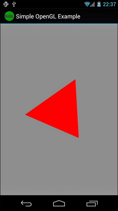
Figure 20.1. A red triangle rendered using OpenGL ES on the Android emulator.
You now have a working OpenGL ES environment in the Android SDK. We continue from this point to talk more about drawing in the environment.
Drawing 3D Objects
Now that you have the OpenGL ES environment working within Android, it’s time to do some actual drawing. This section leads you through a number of examples, each building upon the previous. In doing so, these examples introduce new Android-specific concepts with OpenGL ES.
Drawing Your Vertices
OpenGL ES supports two primary drawing calls, glDrawArrays() and glDrawElements(). Both of these methods require the use of a vertex buffer assigned through a call to glVertexPointer. Because Android runs on top of Java, though, an arbitrary array cannot be passed in as the array contents might move around in memory. Instead, we have to use a ByteBuffer, FloatBuffer, or IntBuffer so the data stays at the same location in memory. Converting various arrays to buffers is common, so we have implemented some helper methods. Here is one for converting a float array into a FloatBuffer:
FloatBuffer getFloatBufferFromFloatArray(float array[]) {
ByteBuffer tempBuffer =
ByteBuffer.allocateDirect(array.length * 4);
tempBuffer.order(ByteOrder.nativeOrder());
FloatBuffer buffer = tempBuffer.asFloatBuffer();
buffer.put(array);
buffer.position(0);
return buffer;
}
This creates a buffer of 32-bit float values with a stride of 0. You can then store the resulting FloatBuffer and assign it to OpenGL calls. Here is an example of doing this, using the triangle we showed previously in this chapter:
float[] vertices = {
-0.559016994f, 0, 0,
0.25f, 0.5f, 0f,
0.25f, -0.5f, 0f
};
mVertexBuffer = getFloatBufferFromFloatArray(vertices);
With the buffer assigned, we can now draw the triangle, as shown here:
void drawTriangle(GL10 gl) {
gl.glEnableClientState(GL10.GL_VERTEX_ARRAY);
gl.glVertexPointer(3, GL10.GL_FLOAT, 0, mVertexBuffer);
gl.glDrawArrays(GL10.GL_TRIANGLES, 0, 3);
}
We have to enable the GL_VERTEX_ARRAY state, though you can do this in GL configuration, as it is required to draw anything with OpenGL ES. We then assign the vertex buffer through a call to glVertexPointer(), also telling GL that we’re using float values. Fixed point values, through GL_FIXED, can also be used and might be faster with some Android implementations. Finally, a call to glDrawArrays() is made to draw the triangles using three vertices from the vertex buffer. The result of this can be seen in Figure 20.1.
Coloring Your Vertices
In OpenGL ES, you can use an array of colors to individually assign colors to each vertex that is drawn. This is accomplished by calling the glColorPointer() method with a buffer of colors. The following code sets up a small buffer of colors for three vertices:
float[] colors = {
1f, 0, 0, 1f,
0, 1f, 0, 1f,
0, 0, 1f, 1f
};
mColorBuffer = getFloatBufferFromFloatArray(colors);
With the buffer available, we can now use it to color our triangle, as shown in the following code:
void drawColorful(GL10 gl) {
gl.glEnableClientState(GL10.GL_COLOR_ARRAY);
gl.glColorPointer(4, GL10.GL_FLOAT, 0, mColorBuffer);
draw(gl);
gl.glDisableClientState(GL10.GL_COLOR_ARRAY);
}
First, the client state for GL_COLOR_ARRAY is enabled. Then, calling the glColorPointer method sets the preceding color buffer created. The call to draw() draws the triangle like the colorful one shown in Figure 20.2.
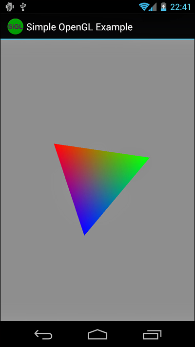
Figure 20.2. A triangle with red, green, and blue vertices smoothly blended.
Drawing More Complex Objects
A standard cube has eight vertices. However, in OpenGL ES, each of the six faces needs to be drawn with two triangles. Each of these triangles needs three vertices. That’s a total of 36 vertices to draw an object with just 8 of its own vertices. There must be a better way.
OpenGL ES supports index arrays. An index array is a list of vertex indexes from the current vertex array. The index array must be a buffer, and in this example, we use a ByteBuffer because we don’t have many vertices to indicate. The index array lists the order that the vertices should be drawn when used with glDrawElements(). Note that the color arrays (and normal arrays that we get to shortly) are still relative to the vertex array and not the index array. Here is some code that draws an OpenGL cube using just eight defined vertices:
float vertices[] = {
-1,1,1, 1,1,1, 1,-1,1, -1,-1,1,
1,1,-1, -1,1,-1, -1,-1,-1, 1,-1,-1
};
byte indices[] = {
0,1,2, 2,3,0, 1,4,7, 7,2,1, 0,3,6, 6,5,0,
3,2,7, 7,6,3, 0,1,4, 4,5,0, 5,6,7, 7,4,5
};
FloatBuffer vertexBuffer =
getFloatBufferFromFloatArray(vertices);
ByteBuffer indexBuffer =
getByteBufferFromByteArray(indices);
gl.glVertexPointer(3, GL10.GL_FLOAT, 0, vertexBuffer);
gl.glDrawElements(GL10.GL_TRIANGLES, indices.length,
GL10.GL_UNSIGNED_BYTE, indexBuffer);
The vertices define the typical shape for a cube. Then, however, we use the index array to define in what order the vertices are drawn to create the cube out of the 12 triangles that we need (recalling that OpenGL ES does not support quads). Now you have a red shape on your screen that looks like Figure 20.3 (left). It doesn’t actually look much like a cube, though, does it? Without some shading, it looks too much like a random polygon. If, however, you switch the glDrawElements() to GL_LINE_LOOP instead of GL_TRIANGLES, you see a line-drawing version of the shape, such as Figure 20.3 (right). Now you can see that it is a cube. You can reuse the vertices buffer with different index buffers, too. This is useful if you can define multiple shapes using the same set of vertices and then draw them in their own locations with transformations.
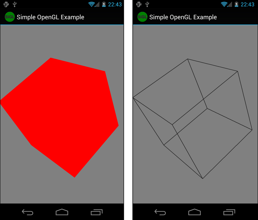
Figure 20.3. A solid cube with no shading (left) and the same cube with only lines (right). (Colors modified for print.)
Lighting Your Scene
The last 3D object that we drew was a cube that looked like some strange polygon on your flat 2D screen. The colors of each face could be made different by applying coloring between each call to draw a face. However, that still produces a fairly flat-looking cube. Instead, why not shine some light on the scene and let the lighting give the cube some additional depth?
Before you can provide lighting on a scene, each vertex of each surface needs a vector applied to it to define how the light reflects and, thus, how it is rendered. Although this vector can be anything, most often it is perpendicular to the surface defined by the vertices; this is called the normal of a surface. Recalling our cube from the preceding example, we see now that a cube can’t actually be created out of eight vertices as each vertex can carry only one normal array, and we would need three per vertex because each vertex belongs to three faces. Instead, we have to use a cube that does, in fact, contain the entire lot of 24 vertices. (Technically, you can define a bunch of index arrays and change the normal array between calls to each face, but it’s more commonly done with a large list of vertices and a single list of normal vectors.)
Like the color array, the normal array is applied to each vertex in the vertex array in order. Lighting is a fairly complex topic and if it’s unfamiliar, you need to check out the “References and More Information” section at the end of this chapter where you can learn more. For now, we just give an example of how to use the lighting features of Open GL ES in Android.
Here is some code for enabling simple lighting:
mGL.glEnable(GL10.GL_LIGHTING);
mGL.glEnable(GL10.GL_LIGHT0);
mGL.glLightfv(GL10.GL_LIGHT0, GL10.GL_AMBIENT,
new float[] {0.1f, 0.1f, 0.1f, 1f}, 0);
mGL.glLightfv(GL10.GL_LIGHT0, GL10.GL_DIFFUSE,
new float[] {1f, 1f, 1f, 1f}, 0);
mGL.glLightfv(GL10.GL_LIGHT0, GL10.GL_POSITION,
new float[] {10f, 0f, 10f, 1f}, 0);
mGL.glEnable(GL10.GL_COLOR_MATERIAL);
mGL.glShadeModel(GL10.GL_SMOOTH);
This code enables lighting, enables GL_LIGHT0, and then sets the color and brightness of the light. Finally, the light is positioned in 3D space. In addition, we enable GL_COLOR_MATERIAL so the color set for drawing the objects is used with the lighting. We also enable the smooth shading model, which helps remove the visual transition between triangles on the same face. You can use color material definitions for fancier lighting and more realistic-looking surfaces, but that is beyond the scope of this book.
Here is the drawing code for our cube, assuming we now have a full vertex array of all 24 points and an index array defining the order in which they should be drawn:
gl.glEnableClientState(GL10.GL_NORMAL_ARRAY);
gl.glVertexPointer(3, GL10.GL_FLOAT, 0, mVertexBuffer);
gl.glNormalPointer(GL10.GL_FLOAT, 0, mNormalBuffer);
gl.glDrawElements(GL10.GL_TRIANGLES, indices.length,
GL10.GL_UNSIGNED_BYTE, mIndexBuffer);
Notice that the normal array and normal mode are now turned on. Without this, the lighting won’t look right. As with the other arrays, this has to be assigned through a fixed buffer in Java, as this code demonstrates:
float normals[] = {
// front
0, 0, 1, 0, 0, 1, 0, 0, 1, 0, 0, 1,
// back
0, 0, -1, 0, 0, -1, 0, 0, -1, 0, 0, -1,
// top
0, 1, 0, 0, 1, 0, 0, 1, 0, 0, 1, 0,
// bottom
0, -1, 0, 0, -1, 0, 0, -1, 0, 0, -1, 0,
// right
1, 0, 0, 1, 0, 0, 1, 0, 0, 1, 0, 0,
// left
-1, 0, 0, -1, 0, 0, -1, 0, 0, -1, 0, 0 };
mNormalBuffer = getFloatBufferFromFloatArray(normals);
The preceding code uses one of the helper methods we talked about previously to create a FloatBuffer. We use a floating point array for the normals. This also shows the normals and how each vertex must have one. (Recall that we now have 24 vertices for the cube.) You can create various lighting effects by making the normals not actually perpendicular to the surface, but for more accurate lighting, it’s usually better to just increase the polygon count of your objects or add textures. Figure 20.4 shows the solid cube, now shaded to show depth better.
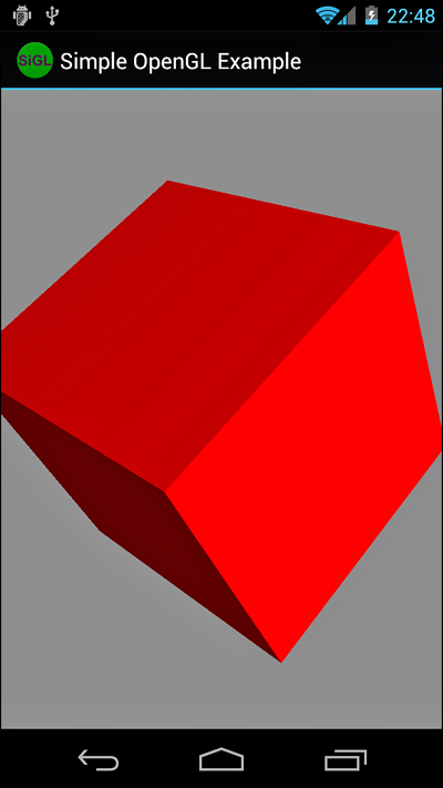
Figure 20.4. A cube with a light shining from the right to shade it.
Texturing Your Objects
Texturing surfaces, or putting images on surfaces, is a rather lengthy and complex topic. It’s enough for our purposes to focus on learning how to texture with Android, so we use the previously lit and colored cube and texture it.
First, texturing needs to be enabled, as shown in the following code:
mGL.glEnable(GL10.GL_TEXTURE_2D);
int[] textures = new int[1];
mGL.glGenTextures(1, textures, 0);
This code enables texturing and creates an internally named slot for one texture. We use this slot to tell OpenGL what texture we operate on in the next block of code:
gl.glBindTexture(GL10.GL_TEXTURE_2D, textures[0]);
Bitmap bitmap = BitmapFactory.decodeResource(
c.getResources(), R.drawable.android);
Bitmap bitmap256 = Bitmap.createScaledBitmap(
bitmap, 256, 256, false);
GLUtils.texImage2D(GL10.GL_TEXTURE_2D, 0, bitmap256, 0);
bitmap.recycle();
bitmap256.recycle();
You’ve probably begun to wonder what happened to Android-specific code. Well, it’s back. OpenGL ES needs bitmaps to use as textures. Lucky for us, Android comes with a Bitmap class that can read in nearly any format of image, including PNG, GIF, and JPG files. You can do this straight from a Drawable resource identifier, too, as demonstrated in the preceding code. OpenGL requires that textures be square and have sides that are powers of two, such as 64 x 64 or 256 x 256. Because the source image might or might not be in one of these exact sizes, we scale it again with just a single Android method call. If the source image weren’t square, though, the original aspect ratio is not kept. Sometimes it is easier to scale down with the original aspect ratio and add colored padding around the edges of the image instead of stretching it, but this is beyond the scope of this example.
Finally, GLUtils.texImage2D() assigns an Android Bitmap to an OpenGL texture. OpenGL keeps the image internally, so we can clean up the Bitmap objects with a call to the recycle() method.
Now that OpenGL ES knows about the texture, the next step is to tell it where to draw the texture. You can accomplish this through using a texture coordinate buffer. This is similar to all the other buffer arrays in that it must be assigned to a fixed Java buffer and enabled. Here is the code to do this with our cube example:
float texCoords[] = {
1,0, 1,1, 0,1, 0,0,
1,0, 1,1, 0,1, 0,0,
1,0, 1,1, 0,1, 0,0,
1,0, 1,1, 0,1, 0,0,
1,0, 1,1, 0,1, 0,0,
1,0, 1,1, 0,1, 0,0,
};
mCoordBuffer = getFloatBufferFromFloatArray(texCoords);
gl.glEnableClientState(GL10.GL_TEXTURE_COORD_ARRAY);
gl.glTexCoordPointer(2, GL10.GL_FLOAT, 0, mCoordBuffer);
draw(gl);
As promised, this code creates a fixed buffer for the texture coordinates. We set the same ones on each face of the cube, so each vertex has a texture coordinate assigned to it (0,0 is the lower-left portion of the texture and 1,1 is the upper-right). Next, we enable the GL_TEXTURE_COORD_ARRAY state and then tell OpenGL which buffer to use. Finally, we draw the cube. Now, we left the code the same as before, which produces the output you see in Figure 20.5 (left). The coloring does still apply, even with textures. If coloring is not applied, the output looks like what you see in Figure 20.5 (right).
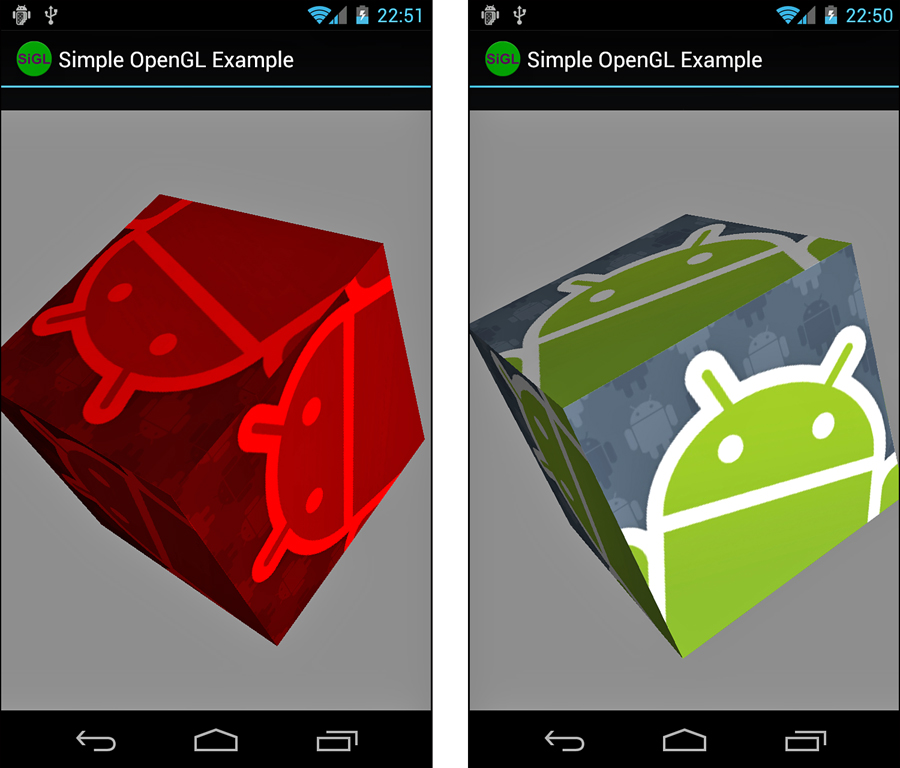
Figure 20.5. A red colored cube with texture (left) and the same cube without red coloring (right).
Interacting with Android Views and Events
Now that you have gone through this introduction to OpenGL ES on Android, you have seen how to draw 3D objects on the screen. Actually, these 3D objects are drawn on a SurfaceView, which has all the typical Android attributes found on View widgets. We now use these attributes to interact with the rest of the application.
First, we show you how to send information from the OpenGL thread back to the main thread to monitor performance. Then, we give an example of how to forward key events from the main thread to the OpenGL thread to control the animation on the screen.
Enabling the OpenGL Thread to Talk to the Application Thread
The Android SDK provides a helper class for running code on another thread. The Handler class can allow a piece of code to run on a target thread—the thread that the Handler was instantiated in. For the purpose of this example, you do this in the Activity class:
public final Handler mHandler = new Handler();
This enables the OpenGL thread to execute code on the Activity thread by calling the post() method of the Handler. This enables us to act on other View objects on the screen that we can’t act on from outside of the Activity thread on the OpenGL thread. For this example, the frame rate of the scene rendered is calculated in the OpenGL thread and then posted back to the Activity thread. Here is a method that does just that:
public void calculateAndDisplayFPS() {
if (showFPS) {
long thisTime = System.currentTimeMillis();
if (thisTime - mLastTime < mSkipTime) {
mFrames++;
} else {
mFrames++;
final long fps =
mFrames / ((thisTime-mLastTime)/1000);
mFrames = 0;
mLastTime = thisTime;
mHandler.post(new Runnable() {
public void run() {
mFPSText.setText("FPS = " + fps);
}
});
}
}
}
The calculateAndDisplayFPS() method is called from within the animation loop of the OpenGL thread. The math is fairly straightforward: the number of frames divided by the duration for those frames in seconds. Then, we take that and post it to the Handler for the Activity thread by creating a new Runnable object that applies a String to the TextView that holds the current frame rate.
However, doing this for every iteration causes the performance to drop substantially. Instead, a counter tracks the number of frames drawn, and we do the calculation and display every time the duration of mSkipTime has gone by. A value of 5000ms has worked well to avoid influencing the performance too much by simply measuring the performance. Figure 20.6 shows the display with the frame rate.
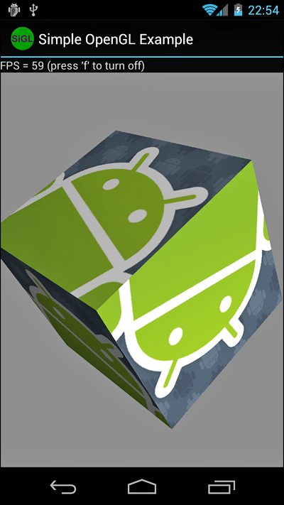
Figure 20.6. A textured, lit, shaded cube with the frame rate displayed.
Enabling the Application Thread to Talk to the OpenGL Thread
Now let’s look at the reverse situation. We want the main application thread to communicate with the OpenGL thread. We can use a Handler to post code to the OpenGL thread for execution. However, if we are not going to execute any OpenGL code, we aren’t required to run it in the OpenGL thread context. Instead, we can add a key event handler to the SurfaceView to either speed up or stop the animation in the OpenGL thread.
A SurfaceView needs to be the current focus before it receives key events. A couple of method calls configure this:
setFocusable(true);
setFocusableInTouchMode(true);
Setting focusable for both touch modes enables key events to come in regardless of the mode. Now, within the SurfaceView, key event handlers need to be implemented. First, we implement a handler for toggling the frame rate on and off. The following is a sample implementation of the onKeyDown() method override:
public boolean onKeyDown(int keyCode, KeyEvent event) {
switch (keyCode) {
case KeyEvent.KEYCODE_F:
mGLThread.toggleFPSDisplay();
return true;
}
return super.onKeyDown(keyCode, event);
}
When the user presses the F key, a call to the toggleFPSDisplay() method of the OpenGL ES thread is made. This merely changes the state of the boolean flag and then updates the text field status. The onKeyDown() method is called multiple times if the key is held, toggling the display until the key is released. There are multiple methods to prevent this, such as just handling it within onKeyUp() or using different keys to enable and disable the state.
The next control we provide to the user is the ability to pause the animation while the P key is held down. Add the following case statement to onKeyDown():
case KeyEvent.KEYCODE_P:
mGLThread.setAnim(false);
return true;
Here, the state is forced to false regardless of how many times onKeyDown() is called. Next, an implementation of onKeyUp() is needed to resume the animation when the user lifts his finger:
public boolean onKeyUp(int keyCode, KeyEvent event) {
switch (keyCode) {
case KeyEvent.KEYCODE_P:
mGLThread.setAnim(true);
return true;
}
return super.onKeyUp(keyCode, event);
}
Again, the value is forced and set to true so that when the user lifts his finger off the key, the animation resumes regardless of the current state. An if statement around the inner part of the entire while() animation loop can pause the entire rendering in this example.
In these examples, the code does not actually run in the OpenGL thread to change the state of the flags. This is acceptable for the following reasons:
• The values are set in this way exclusively (no concurrency problems).
• The exact state of the flags is unimportant during the loop.
• No calls to OpenGL are made.
The first two reasons mean that we don’t have to perform thread synchronization for the functionality to work acceptably and safely. The last reason means that we don’t need to create a Handler on the OpenGL thread to execute OpenGL calls in the proper thread. There are many circumstances where these aren’t met. Discussing thread synchronization is not within the scope of this chapter, however. Standard Java methods are available for doing this.
Cleaning Up OpenGL ES
It is necessary for your application to clean up OpenGL when your application is done using it. This happens when the application quits or the Activity has changed in some way. The recommended process for gracefully shutting down OpenGL is to reset the surface and context, destroy the surface and context you configured, and then terminate the EGL instance. You can do this with the following code:
private void cleanupGL() {
mEGL.eglMakeCurrent(mGLDisplay, EGL10.EGL_NO_SURFACE,
EGL10.EGL_NO_SURFACE, EGL10.EGL_NO_CONTEXT);
mEGL.eglDestroySurface(mGLDisplay, mGLSurface);
mEGL.eglDestroyContext(mGLDisplay, mGLContext);
mEGL.eglTerminate(mGLDisplay);
}
First, eglMakeCurrent() removes the surface and context that were used. Next, eglDestroySurface() and eglDestroyContext() release any resources held by OpenGL for the surface and the context. Finally, OpenGL is terminated through a call to eglTerminate(). If OpenGL runs in a separate thread, the thread can now be terminated as well.
It is up to the application to clean up OpenGL properly. There are no helper methods available for managing all of it automatically in the Android lifecycle as there are with Cursor objects and the like.
Using GLSurfaceView (Easy OpenGL ES)
Several new classes were introduced with Android 1.5 (API Level 3) that you can use to simplify application OpenGL ES implementation. The GLSurfaceView and GLSurfaceView.Renderer classes effectively require less code to write so that you can focus on the actual GL drawing process instead of the implementation details and upkeep necessary to handle OpenGL ES calls. Essentially, the GLSurfaceView class handles the EGL initialization, threading, and calls in to a user-defined Renderer class. The Renderer class handles the drawing and GL initialization.
The code examples provided in this section are taken from the ShowAndroidGLActivity.java class in the SimpleOpenGL application. The source code for this application is provided for download on the book’s websites.
To use the GLSurfaceView class, you must either extend it or instantiate it directly. Either way, you then need to provide an implementation of a GLSurfaceView.Renderer class. The Renderer class must contain appropriate callbacks for drawing and GL initialization. Additionally, the Activity must pass onPause() and onResume() events on to the GLSurfaceView. The EGL initialization is handled by the GLSurfaceView object, and threading is used to offload the processing away from the main thread.
The following code demonstrates an entire Activity that duplicates the colorful triangle we drew earlier in this chapter, as shown in Figure 20.2:
public class AndroidOpenGL extends Activity {
CustomSurfaceView mAndroidSurface = null;
protected void onPause() {
super.onPause();
mAndroidSurface.onPause();
}
protected void onResume() {
super.onResume();
mAndroidSurface.onResume();
}
protected void onCreate(Bundle savedInstanceState) {
super.onCreate(savedInstanceState);
mAndroidSurface = new CustomSurfaceView(this);
setContentView(mAndroidSurface);
}
private class CustomSurfaceView extends GLSurfaceView {
final CustomRenderer mRenderer = new CustomRenderer();
public CustomSurfaceView(Context context) {
super(context);
setFocusable(true);
setFocusableInTouchMode(true);
setRenderer(mRenderer);
}
public boolean onKeyDown(int keyCode, KeyEvent event) {
switch (keyCode) {
case KeyEvent.KEYCODE_P:
queueEvent(new Runnable() {
public void run() {
mRenderer.togglePause();
}
});
return true;
}
return super.onKeyDown(keyCode, event);
}
}
private class CustomRenderer implements
GLSurfaceView.Renderer {
TriangleSmallGLUT mTriangle = new TriangleSmallGLUT(3);
boolean fAnimPaused = false;
public void onDrawFrame(GL10 gl) {
if (!fAnimPaused) {
gl.glClear(GL10.GL_COLOR_BUFFER_BIT |
GL10.GL_DEPTH_BUFFER_BIT);
gl.glRotatef(1f, 0, 0, 1f);
if (mTriangle != null) {
mTriangle.drawColorful(gl);
}
}
}
public void togglePause() {
if (fAnimPaused == true) {
fAnimPaused = false;
} else {
fAnimPaused = true;
}
}
public void onSurfaceChanged(GL10 gl, int width,
int height) {
gl.glViewport(0, 0, width, height);
// configure projection to screen
gl.glMatrixMode(GL10.GL_PROJECTION);
gl.glLoadIdentity();
gl.glClearColor(0.5f, 0.5f, 0.5f, 1);
float aspect = (float) width / height;
GLU.gluPerspective(gl, 45.0f, aspect, 1.0f, 30.0f);
}
public void onSurfaceCreated(GL10 gl,
EGLConfig config) {
gl.glEnableClientState(GL10.GL_VERTEX_ARRAY);
// configure model space
gl.glMatrixMode(GL10.GL_MODELVIEW);
gl.glLoadIdentity();
GLU.gluLookAt(gl, 0, 0, 10f, 0, 0, 0, 0, 1, 0f);
gl.glColor4f(1f, 0f, 0f, 1f);
}
}}
As you can see, this code demonstrates creating a new GLSurfaceView and a new GLSurfaceView.Renderer. The end result, with proper implementation of the triangle drawing class (included with the book code and discussed earlier in this chapter), is a spinning triangle that the user can pause with the press of the P key. The GLSurfaceView implementation contains its own renderer, which is less generic than assigning it externally, but with the key handling we implemented. The two classes must work closely together.
The GLSurfaceView implements key handling by overriding the onKeyDown() method of the regular View class. The action is passed on to the Renderer through a helper method called queueEvent(). The queueEvent() method passes the Runnable object on to the Renderer thread held by the GLSurfaceView.
Next, the Renderer implementation provides the drawing in the onDrawFrame() method. This is either called continuously or on demand, depending on the render mode set via a call to the GLSurfaceView.setRenderMode() method. The implementation of onSurfaceChanged() is now where we set up the screen projection—an appropriate place because this method is called on orientation or size changes of the surface. Then, in onSurfaceCreated(), the basic GL configuration is performed, including setting client states and static data, such as the model view.
All EGL configuration is now performed internally to GLSurfaceView, so the application need not worry about it. If, however, the application needs to perform custom configuration of the EGL, the EGLConfig object is passed to the onSurfaceCreated() method and is used to perform such custom configuration.
If you choose to use this method to bring up a GL surface on Android, the implementation of the rendering code doesn’t need to change at all.
Using OpenGL ES 2.0
Android began supporting Open GL ES 2.0 in Android 2.2 (API Level 8), although applications that leveraged the Android NDK can use 2.0 features as early as API Level 5 with NDK Release 3. In this section, we discuss the Android Java API support for OpenGL ES 2.0. Support also remains for OpenGL ES 1.x and for good reason. Open GL ES 2.0 is not backward compatible with OpenGL ES 1.x. The different OpenGL ES versions provide different methods of handling 3D graphics:
• OpenGL ES 1.x provides a fixed function rendering and texturing pipeline. That is to say, the math used to transform, light, and color a scene is all the same—fixed functions.
• OpenGL ES 2.0 replaced the fixed functions with vertex and fragment shader programs written, of course, by you, the developer. Writing the shader programs provides much more flexibility, but does incur a bit more overhead on the development side.
The choice of which version of OpenGL ES to use is yours. In this section, we show you how to initialize and get a basic OpenGL ES 2.0 program up and running. Using the NDK method is discussed in Chapter 21.
Many of the code examples provided in this section are taken from the SimpleOpenGL2 application. The source code for this application is provided for download on the book’s websites.
Configuring Your Application for OpenGL ES 2.0
If you’re going to use the Android OpenGL ES 2.0 APIs and aren’t planning on supporting alternate code paths, you need to specify two items in your manifest file: Your application requires Android 2.2 or higher using the <uses-sdk> tag and that it requires OpenGL ES 2.0 using the <uses-feature> tag.
<uses-sdk
android:targetSdkVersion="8"
android:minSdkVersion="8" />
<uses-feature
android:glEsVersion="0x00020000" />
Requesting an OpenGL ES 2.0 Surface
Start by creating your custom SurfaceView, which you usually do within the Activity class onCreate() method, as follows:
mAndroidSurface = new CustomGL2SurfaceView(this);
setContentView(mAndroidSurface);
Of course, you need to implement the CustomGL2SurfaceView class. In our sample project, we did this as an inner class of the Activity, for convenience:
private class CustomGL2SurfaceView extends GLSurfaceView {
final CustomRenderer renderer;
public CustomGL2SurfaceView(Context context) {
super(context);
setEGLContextClientVersion(2);
renderer = new CustomRenderer();
setRenderer(renderer);
}
}
The most important line of code here is the call to the setEGLContextClientVersion() method. This call is made in order to request an EGL context for OpenGL ES 1.x (when the parameter is 1) or OpenGL ES 2.x (when the parameter is 2). Then the custom renderer is set.
Although it might seem confusing, the Renderer methods take GL10 objects. How, then, are you to make OpenGL ES 2.0 calls? The answer turns out to be simple: The GLES20 class is entirely static. Just ignore the GL10 parameters and make calls directly to the GLES20 class.
The CustomRenderer class starts out by initializing the vertices, much as we did earlier. Then, when the onSurfaceCreate() method is called, we can initialize the shader programs, as follows:
@Override
public void onSurfaceCreated(GL10 unused, EGLConfig unused2) {
try {
initShaderProgram(R.raw.simple_vertex, R.raw.simple_fragment);
initialized = true;
} catch (Exception e) {
Log.e(DEBUG_TAG, "Failed to init GL");
}
}
The two resource identifiers, simple_vertex and simple_fragment, simply reference two text files stored as a raw resources. Now, let’s look at the initialization of the shaders:
private int shaderProgram = 0;
private void initShaderProgram(int vertexId, int fragmentId)
throws Exception {
int vertexShader =
loadAndCompileShader(GLES20.GL_VERTEX_SHADER, vertexId);
int fragmentShader =
loadAndCompileShader(GLES20.GL_FRAGMENT_SHADER, fragmentId);
shaderProgram = GLES20.glCreateProgram();
if (shaderProgram == 0) {
throw new Exception("Failed to create shader program");
}
// attach the shaders to the program
GLES20.glAttachShader(shaderProgram, vertexShader);
GLES20.glAttachShader(shaderProgram, fragmentShader);
// bind attribute in our vertex shader
GLES20.glBindAttribLocation(shaderProgram, 0, "vPosition");
// link the shaders
GLES20.glLinkProgram(shaderProgram);
// check the linker status
int[] linkerStatus = new int[1];
GLES20.glGetProgramiv(shaderProgram, GLES20.GL_LINK_STATUS,
linkerStatus, 0);
if (GLES20.GL_TRUE != linkerStatus[0]) {
Log.e(DEBUG_TAG, "Linker Failure: "
+ GLES20.glGetProgramInfoLog(shaderProgram));
GLES20.glDeleteProgram(shaderProgram);
throw new Exception("Program linker failed");
}
GLES20.glClearColor(0.5f, 0.5f, 0.5f, 1);
}
This process does not change substantially for different shaders. Recall that OpenGL ES 2.0 requires both a vertex shader and a fragment shader. First, we load the text for each shader and compile them. Then, we create a new shader program reference, attach both shaders to it, assign an attribute position to our only input parameter, and link the program. Finally, checks are made to confirm that the program linked successfully.
The loading of each shader is handled by our loadAndCompileShader() method. Here is a sample implementation of this method:
private int loadAndCompileShader(int shaderType, int shaderId)
throws Exception {
InputStream inputStream =
AndroidGL2Activity.this.getResources().openRawResource(shaderId);
String shaderCode = inputStreamToString(inputStream);
int shader = GLES20.glCreateShader(shaderType);
if (shader == 0) {
throw new Exception("Can't create shader");
}
// hand the code over to GL
GLES20.glShaderSource(shader, shaderCode);
// compile it
GLES20.glCompileShader(shader);
// get compile status
int[] status = new int[1];
GLES20.glGetShaderiv(shader, GLES20.GL_COMPILE_STATUS, status, 0);
if (status[0] == 0) {
// failed
Log.e(DEBUG_TAG, "Compiler Failure: "
+ GLES20.glGetShaderInfoLog(shader));
GLES20.glDeleteShader(shader);
throw new Exception("Shader compilation failed");
}
return shader;
}
The loadAndCompileShader() method reads in the raw resource as a string. Then the source is handed over to GLES20 via a call to the glShaderSource() method. Finally, the shader is compiled with a call to glCompileShader(). The result is checked to make sure the compile was successful. OpenGL ES 2.0 holds the binary results internally so that they can be used later during linking.
The onSurfaceChanged() method should look quite familiar—it changes little. The viewport is reconfigured for the new display metrics and then the clear color is set. Note again that you can simply use the static GLES20 calls rather than the GL10 parameter.
@Override
public void onSurfaceChanged(GL10 unused, int width, int height) {
Log.v(DEBUG_TAG, "onSurfaceChanged");
GLES20.glViewport(0, 0, width, height);
GLES20.glClearColor(0.5f, 0.5f, 0.5f, 1);
}
Finally, we’re ready to render the triangle. The scene is rendered each time the system calls our onDrawFrame() implementation.
@Override
public void onDrawFrame(GL10 unused) {
if (!initialized) {
return;
}
GLES20.glClear(GLES20.GL_COLOR_BUFFER_BIT);
GLES20.glUseProgram(shaderProgram);
GLES20.glVertexAttribPointer(0, 3, GLES20.GL_FLOAT, false, 12,
verticesBuffer);
GLES20.glEnableVertexAttribArray(0);
GLES20.glDrawArrays(GLES20.GL_TRIANGLES, 0, 3);
}
At this point, the code should also appear familiar. The primary difference here is the call to the glUseProgram() method, where we must pass in the numeric identifier of the program we compiled and linked. The final result is simply a static (motionless) triangle on the screen. It’s not very exciting, considering the amount of code required. The flexibility of the shaders is powerful, but many applications don’t need the extra flexibility that comes with using OpenGL ES 2.0, either.
By now, you might be wondering what the shaders look like. Because the resource system of Android just uses the part of the filename before the extension, we decided to name our shader files very clearly so we could easily tell what they were: simple_vertex.shader and simple_fragment.shader. These are two of the simplest shaders one can define.
First, let’s look at the vertex shader because it’s first in the pipeline:
attribute vec4 vPosition;
void main()
{
gl_Position = vPosition;
}
This has a single input, vPosition, which is simply assigned to the output. No transformations are applied, and we’re not doing any texturing. Now let’s turn our attention to the fragment shader:
precision mediump float;
void main()
{
gl_FragColor = vec4(0.0, 1.0, 0.0, 1.0);
}
This shader is even simpler. It’s assigning a fixed color to the output. In this case, it’s assigning green to the output.
Shader definitions can be quite complex. Implementing lighting, texturing, fog effects, and other interesting OpenGL ES 2.0 features that can’t be fashioned using the fixed pipeline of OpenGL ES 1.x is far beyond the scope of this book. However, we’d recommend picking up a book on OpenGL ES 2.0, such as OpenGL ES 2.0 Programming Guide by Aaftab Munshi, Dan Gisnburg, and Dave Shreiner (Addison-Wesley, 2008, ISBN: 0321502795) or OpenGL SuperBible by Richard S. Wright, Jr., Nicholas Haemel, Graham Sellers, and Benjamin Lipchak (Addison-Wesley, 2010, ISBN: 0321712617), or finding resources online.
Working with RenderScript
RenderScript is a set of high-performance graphics and computation APIs that was introduced in Android 3.0 (API Level 11). RenderScript uses a C language (C99, specifically) for writing scripts. Through intermediate compilation, RenderScript is designed to run on a variety of processor architectures, providing a means of writing performance-critical code that the system later compiles to native code for the processor it can run on. This can be the device CPU, a multi-core CPU, or even the GPU. As of this writing, only the CPU is a target.
RenderScript is based on the C programming language. If you’re not familiar with C, we recommend that you get familiar with it first before trying to use RenderScript. Although RenderScript is not OpenGL, nor does it require that you use it for graphics rendering, the concepts for using it are similar to OpenGL concepts. And, indeed, the underlying graphics rendering is done with OpenGL ES 2; however, RenderScript exposes only a subset of the functionality available in OpenGL ES. Therefore, familiarity with OpenGL and 3D graphics terminology helps here, as it has for the other portions of this chapter.
Although RenderScript is more limiting than using OpenGL ES in the 3D rendering area, the addition of compute-only RenderScript adds some welcome capabilities. Drawing a quick 3D scene using RenderScript might be more efficient in terms of coding than using OpenGL. Using RenderScript for heavy computation or image manipulation might be faster to develop and it might perform better than similar NDK solutions (due to automatic distribution across hardware cores). Unlike developing with the Android NDK, you don’t have to worry about the underlying hardware architecture. In fact, when it comes to NDK limitations, such as no support for Google TV, Render-Script has fewer. It does work on Google TV.
The code examples provided in this section are taken from the SimpleRenderscript application. The source code for this sample application is provided for download on the book’s websites.
Defining RenderScript Functionality
So, let’s see an example of an Android application that leverages Renderscript. Let’s assume you start with an existing Android project in Eclipse. RenderScript files are stored in your source tree as files that have the .rs file suffix. For example, we are going to create a simple snowflake animation, so we add a file called snow.rs.
RenderScript generates an intermediate binary file in the res/raw directory. For example, snow.rs creates a file called snow.bc (bc for LLVM bitcode, the intermediate binary format). This file should not be checked in to source control. We recommend adding an ignore definition for your source control to keep all .bc files out.
RenderScript files begin with a definition of the RenderScript version; the only valid value is 1, currently. This is followed by the Java package name associated with your application. Next, you add your #include statements for the RenderScript headers your application needs (in this example, we use the rs_graphics.rsh header to access some simple graphics functions).
#pragma version(1)
#pragma rs java_package_name(com.androidbook.simplerenderscript)
#include "rs_graphics.rsh"
Now let’s define some global variables. First, we define the mesh. It maps to the Mesh object on the Java side, which is where we initialize the memory for it. A mesh is similar to a vertex buffer in OpenGL. For this example, the mesh is made up of points, but we define that in Java later. While you’re at it, create a couple of variables to hold wind and gravity values.
rs_mesh snowMesh;
typedef struct __attribute__((packed, aligned(4))) Snow {
float2 velocity;
float2 position;
uchar4 color;
} Snow_t;
Snow_t *snow;
float2 wind;
float2 grav;
RenderScript has two special functions: root() and init(). The root() function is the rendering loop. It is called each time the system needs to draw the scene. The return value defines whether the script runs once (return 0) or at N-millisecond intervals (return N). If the hardware can’t keep up with the requested frequency, then root() runs as often as it can. The init() function is automatically called once when the script loads and is a good place to initialize variables and other state parameters. Initialize the wind and gravity in the init() function:
void init() {
grav.x = 0;
grav.y = 18;
wind.x = rsRand(50)+20;
wind.y = rsRand(4) - 2;
}
Initialize the snow in its own helper function. Because the mesh is allocated in Java, we first determine how big it is with a call to the rsAllocationGetDimX() function to get the array dimensions so we know how many points we’re initializing. The function takes an rs_allocation, which is basically a reference to the memory being managed by RenderScript. Next, iterate over each structure and set some random values for the snowflake data, so the snow will appear natural (or at least evenly distributed).
void initSnow() {
const float w = rsgGetWidth();
const float h = rsgGetHeight();
int snowCount = rsAllocationGetDimX(rsGetAllocation(snow));
Snow_t *pSnow = snow;
for (int i=0; i < snowCount; i++) {
pSnow->position.x = rsRand(w);
pSnow->position.y = rsRand(h);
pSnow->velocity.y = rsRand(60);
pSnow->velocity.x = rsRand(100);
pSnow->velocity.x -= 50;
uchar4 c = rsPackColorTo8888(255, 255, 255);
pSnow->color = c;
pSnow++;
}
}
At this point, we make a two-line root() function that draws the scene as-is. It draws the same every time, of course.
int root() {
rsgClearColor(0.0f, 0.0f, 0.0f, 0.0f);
rsgDrawMesh(snowMesh);
return 0;
}
The rsgClearColor() function is basically the same as the glClear() function of OpenGL. Then we call the rsgDrawMesh() function, passing in the mesh we’ve configured. This is somewhat like a call to glDrawArrays() of OpenGL.
Let’s update the root() function to animate the snowflakes. Begin by clearing the drawing area using the rsgClearColor() function. Then, for some simple pseudo-physics-style simulation, iterate over each snowflake and apply its current velocity and wind to its position, then adjust the velocity based on gravity acceleration. Finally, check to see whether any snowflakes have fallen off the bottom of the screen and move them back to the top of the screen as needed. Finally, redraw the updated mesh using the rsgDrawMesh() function.
int root() {
rsgClearColor(0.0f, 0.0f, 0.0f, 0.0f);
float dt = min(rsGetDt(), 0.1f);
float w = rsgGetWidth();
float h = rsgGetHeight();
int snowCount = rsAllocationGetDimX(rsGetAllocation(snow));
Snow_t *pSnow = snow;
for (int i=0; i < snowCount; i++) {
pSnow->position.x += ((pSnow->velocity.x +wind.x) * dt);
pSnow->position.y += ((pSnow->velocity.y +wind.y) * dt);
if (pSnow->position.y > h) {
pSnow->position.y = 0;
pSnow->position.x = rsRand(w);
pSnow->velocity.y = rsRand(60);
}
pSnow->velocity.x += (grav.x)*dt;
pSnow->velocity.y += (grav.y)*dt;
pSnow++;
}
rsgDrawMesh(snowMesh);
return 30;
}
When you save the script project file in Eclipse, the builders automatically create a file called snow.bc in the /res/raw directory. This automatically generated file should not be checked into source control, nor should it be modified. In addition, some Java files are created in the /gen folder. These are the interface files used for calling into the script from Android.
Now that the script is created, we need to initialize it for use from within your Android classes. To do this, we created a helper Java class called SnowRS.java. In it, we allocate the memory for the snow flakes, initialize the script, and bind the mesh and snow flake allocation to it. This class also uses a RenderScriptGL object.
public class SnowRS {
public static final int SNOW_FLAKES = 4000;
private ScriptC_snow mScript;
private Resources mResources;
private RenderScriptGL mRS;
public SnowRS() {
}
public void stop() {
mRS.bindRootScript(null);
}
public void start() {
mRS.bindRootScript(mScript);
}
public void init(RenderScriptGL rs, Resources res) {
mRS = rs;
mResources = res;
mScript = (ScriptC_snow) createScript();
}
public ScriptC createScript() {
ScriptField_Snow snow = new ScriptField_Snow(mRS, SNOW_FLAKES);
Mesh.AllocationBuilder smb = new Mesh.AllocationBuilder(mRS);
smb.addVertexAllocation(snow.getAllocation());
smb.addIndexSetType(Mesh.Primitive.POINT);
Mesh sm = smb.create();
ScriptC_snow script;
script = new ScriptC_snow(mRS, mResources, R.raw.snow);
script.set_snowMesh(sm);
script.bind_snow(snow);
script.invoke_initSnow();
return script;
}
}
Let’s take a closer look at the createScript() method, as that’s where the memory and rendering initialization take place. First, it initializes a structure array of 4,000 snowflakes. This is then used to create a Mesh object used for rendering. The rendering construct is set to POINT, so each snowflake shows up as a pixel on the screen. Next, the script itself is created and initialized using the raw resource entry created by the Eclipse builder. Then, we assign the Mesh and the array allocation into the script via the calls set_snowMesh() and bind_snow(), respectively. Finally, we initialize the snow with a call to the initSnow() function we created earlier by calling invoke_initSnow(). The script does not start running at this point, but the init() function has been called. To get the script running, call bindRootScript() on the script object, as seen in the start() method.
Rendering to a Custom View Control
The Android SDK provides just the means we need to display our RenderScript: the RSSurfaceView class. Implement a class called FallingSnowView that extends the RSSurfaceView class, like this:
public class FallingSnowView extends RSSurfaceView {
private RenderScriptGL mRSGL;
private SnowRS mRender;
public FallingSnowView(Context context) {
super(context);
}
@Override
public void surfaceChanged(SurfaceHolder holder, int format,
int w, int h) {
super.surfaceChanged(holder, format, w, h);
if (mRSGL == null) {
RenderScriptGL.SurfaceConfig sc =
new RenderScriptGL.SurfaceConfig();
mRSGL = createRenderScriptGL(sc);
mRSGL.setSurface(holder, w, h);
mRender = new SnowRS(w, h);
mRender.init(mRSGL, getResources(), false);
mRender.start();
}
}
@Override
protected void onDetachedFromWindow() {
if (mRSGL != null) {
mRSGL = null;
destroyRenderScriptGL();
}
}
}
The magic here is in the surfaceChanged() method. Here we create a RenderScriptGL object from the SurfaceHolder incoming parameter. Next, the SnowRS object is instantiated and rendering is started with the start() method. To clean up, we call the destroyRenderScriptGL() method in the onDetachedFromWindow() callback method.
You now have everything in place to use the FallingSnowView class in your Activity class. The onCreate() method of your Activity class can be as simple as this:
public class SimpleRenderscriptActivity extends Activity {
private FallingSnowView snowView;
@Override
public void onCreate(Bundle savedInstanceState) {
super.onCreate(savedInstanceState);
snowView = new FallingSnowView(this);
setContentView(snowView);
}
@Override
protected void onResume() {
super.onResume();
snowView.resume();
}
@Override
protected void onPause() {
super.onPause();
snowView.pause();
}
}
A frame of the resulting scene is shown in Figure 20.7.
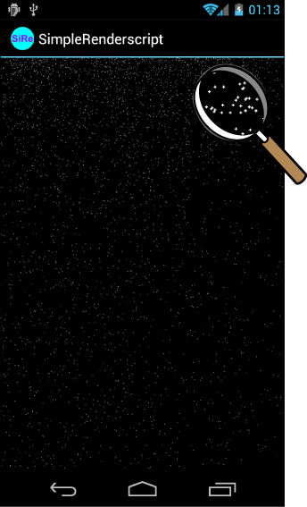
Figure 20.7. The snow is falling in our RenderScript animation example.
There you go. You have now mastered the basics of initializing RenderScript and rendering to the screen. All of this was done in the context of a simple particle system simulating pixel-sized snowflakes. RenderScript can do a lot more, though. You can use a RenderScript for graphics rendering or computational purposes. You can use it to apply graphical effects to bitmaps or add shaders to leverage device graphics hardware to draw the scene differently. You can move the pseudo-physics for the snow to its own compute RenderScript. You can set up transformations to draw in a 3D space. You can configure textures to draw. You can set shaders called programs in RenderScript using the OpenGL shader language GLSL. See the Android SDK documentation for more details.
Summary
In this chapter, you learned the basics for using OpenGL ES from within an Android application. You also learned about the different versions of OpenGL ES supported by the Android platform and the high-performance graphics and compute features available as part of RenderScript.
You learned about several ways to use OpenGL ES in your Android applications. You learned how to initialize OpenGL ES in its own thread. Then you learned how to draw, color, and light objects using a variety of OpenGL and Android helper methods. You then learned how your application thread and the OpenGL thread can interact with each other. Finally, you learned how to clean up OpenGL.
Creating fully functional 3D applications and games is a vast topic, more than enough to fill entire books. You have learned enough to get started drawing in three dimensions on Android and can use the knowledge to apply general OpenGL concepts to Android. The reference section that follows contains links to more information to help you deepen your OpenGL ES knowledge.
References and More Information
Khronos OpenGL ES overview:
http://www.khronos.org/opengles/
OpenGL ES 1.1 API documentation:
http://www.khronos.org/opengles/sdk/1.1/docs/man/
OpenGL ES 2.0 API documentation:
http://www.khronos.org/opengles/sdk/2.0/docs/man/
OpenGL ES information:
Android Dev Guide: “RenderScript”:
http://d.android.com/guide/topics/renderscript/index.html
Android Dev Guide: “RenderScript Graphics”:
http://d.android.com/guide/topics/renderscript/graphics.html
Android Dev Guide: “RenderScript Compute”:
http://d.android.com/guide/topics/renderscript/compute.html
Android Dev Guide: “RenderScript Runtime API Reference”:
http://d.android.com/guide/topics/renderscript/reference.html