Chapter 3: Designing the Network
The network is the foundation of a compute infrastructure, and any design decision you make at this level is very hard to revert later on. Therefore, it is essential to get things right from the start of the network architecture.
In this chapter, you will learn Google Cloud's approach to networking and its available services, as well as the design considerations for building networks and setting up hybrid connectivity between an on-premises environment (or another cloud) and Google Cloud. You will also learn how to create a shared virtual private cloud (VPC) to share networks across projects, as well as how to configure routes and firewall access on networks. Finally, you will learn about some of the common network designs in Google Cloud.
In this chapter, we're going to cover the following main topics:
- Designing networks and subnetworks
- Understanding routes and firewalls in Google Cloud
- Understanding load balancing in Google Cloud
- Designing for hybrid connectivity
- Mastering common network designs
Let's get started!
Technical requirements
Check out the following link to see the Code in Action video: https://bit.ly/3c3CVYn
Designing networks and subnetworks
A network in GCP is called a VPC, and it differs from the way other cloud platforms define virtual networks in that it is a more purely logical construct, with no IP address range defined in it. It is also global by default, spanning all available GCP regions, and it is segmented by subnetworks (the equivalent to what is referred to as subnets in other cloud platforms), which themselves have IP address ranges and a set region. A GCP project can have up to five VPC networks (although this quota can be increased upon request), and networks can be shared across projects and also peered with each other.
There are three network types (or "modes") in GCP, as follows:
- Default: Provided by default to every new project. It contains one subnetwork per region and includes some default firewall rules. These default rules allow all traffic within the network, as well as inbound RDP, SSH, and ICMP from any other network.
- Auto: Auto mode creates one subnetwork per region automatically with an expandable address range. The default network is, in fact, an auto mode network. When creating an auto mode network, the default firewall rules (which would be automatically deployed in the default network) are suggested in the creation form. Still, you can select which specific ones you want to deploy and there's the option to not select any of them and, therefore, not deploy any firewall rules on creation. This means every piece of network traffic will be blocked until a rule is created at a later point.
- Custom: In this mode, no default subnetworks are created, so you can specify in which regions you want subnetworks in. You also have full control over their IP ranges, as long as they're within the private RFC 1918 address space. You can convert an already existing auto mode network into a custom mode network to customize it to your needs. However, you cannot convert a custom mode network back into auto mode.
Because subnetworks are regional in scope, they cross all the different zones within each region. This means that two VMs can be in the same subnetwork but deployed to different zones (which often means different data centers).
All networks have managed routing capability, which means you don't need to set up routes yourself for network communication across different subnetworks and regions of a VPC network. In addition, with the default and auto mode networks, firewall rules are also automatically set up (optionally, in the case of auto mode networks) to allow any communication that may occur within the network, even if it's going across different subnetworks and regions. With custom networks, these firewall rules won't be created automatically, but you can create them yourself and customize them to the security level you want.
Important Note
Although default and auto networks have been designed so that you can get started easily, you shouldn't use these options in an enterprise-grade solution. The firewall rules that allow all communications within the network and management protocols (such as RDP, SSH, and ICMP) to the outside world, though convenient, are too permissive and go against network security best practices and the zero trust principle, which we will discuss later in this chapter. The auto mode network could be used for truly global solutions, but generally, the suggested firewall rules should not be selected when creating the network.
Because Google's VPC networks are global, you can connect an on-premises network to all your GCP subnetworks (in different regions) with a single VPN gateway service. That way, it becomes significantly easier to extend your on-premises network to global reach with GCP.
Multi-project networking
When working with multiple projects and networks under the same organization in Google Cloud, there are two essential features to consider: shared VPC and VPC peering.
Let's look at what they are.
Shared VPC
The idea behind a shared VPC is to host a single network within a designated GCP project (referred to as the host project), which allows it to be shared with one or more projects (referred to as service projects) to centralize and simplify network management and security controls. In this model, the resources in the service projects can be deployed to one of the subnetworks of the shared VPC (belonging to the host project). Network and security policies can be applied to this one single, centralized network.
Security best practices and the least privilege principle are facilitated with the shared VPC model, since network administration tasks can be delegated to and centralized by network and security admins in the shared VPC network. Administrators in the service projects cannot make any changes that impact the network in any way. This also helps keep access control policies consistent across different projects in the organization.
When a project is set as a host project, all existing and new VPC networks will automatically become a shared VPC network. Therefore, this is a project-level definition, and you can't determine specific networks within a host project that should become shared VPCs.
When it comes to subnetworks, you can define which subnetworks can be accessed by a specific service project within the host project. This allows you to assign different subnetworks to different projects and keep them segregated (via firewall rules) if needed.
VPC peering
In GCP, two networks can be peered as long as they don't have overlapping IP address ranges. What peering means is that their route tables will be shared, and the underlying platform (Google's software-defined network) will be set up so that these two networks can be reached by each another. This effectively means you will have all your subnetworks (layer 2 network domains) across both VPC networks connected via a managed layer 3 router (which you do not need to concern yourself with). One way to think about this is that you're merely extending one of the networks with another network as if to obtain a single VPC network with a larger address space. We are, of course, talking about reachability at the network layer – things still need to be allowed in the firewall for communication to happen, and any IAM permissions granted at the VPC network level won't translate over to peered VPC networks.
VPC peering is non-transitive, which means that if VPC A is peered with VPC B, and VPC C is peered with VPC B, the resources in VPC C won't be able to reach the resources in VPC A (and vice versa) through the peerings. This is because route exchange only supports propagating routes to an immediate peer, not to peers of peers. This has implications on the scalability of, for example, a hub-and-spoke network model. Popularized by Microsoft as an ideal topology for sharing managed Active Directory (AD) installations and other shared services, the hub-and-spoke model involves one centralized hub network, and several "spoke" networks that are peered with the hub (and therefore can reach its shared services, such as AD domain controllers). The hub is also where a VPN gateway is deployed to for connectivity to on-premises networks. The general idea is that the resources in any of the "spoke" networks can reach on-premises resources (and vice versa) through the hub. However, due to the route exchange limitation of GCP, this design won't work as intended, unless you're deploying a smaller version of a hub-and-spoke model and you have no requirement for reachability between your spokes and on-premises. You can work around this limitation by setting up VPNs between VPCs, as opposed to peerings, though this is non-ideal, given the extra cost of VPN tunnels and extra management overhead on the network. For that reason, if you want to achieve something similar to that of a hub-and-spoke model, you should use a shared VPC.
IP addresses
In GCP, VMs can have two types of IP addresses:
- Internal IP: This is an IP in the private space, allocated from the subnetwork range by DHCP. An internal (network-scoped) DNS name is associated with this IP, based on its VM hostname and following the structure:
[hostname].c.[project-id].internal
Internal IPs can be static (DHCP-reserved) or ephemeral, in which case it might change upon, for example, the instance being restarted.
- External IP: This is a public IP that is dynamically assigned by GCP from an address pool when configured as ephemeral, or with a reserved address when configured as static. An external IP is never directly attached to a VM (and therefore not visible from within the VM's operating system). Rather, it's an IP address that is mapped to the VM's internal IP so that, effectively, the external IP "belongs" to the VM. DNS records can be published using existing DNS servers (outside of GCP, or within GCP when hosting the DNS zone for the domain using the cloud DNS service – more on that later).
You can also assign a range of IP addresses as aliases to a VM instance's primary IP address. This feature allows you to assign separate IPs to separate services running on the same VM instance, making it particularly useful for use cases involving containerization. You can also set up a secondary CIDR range in your subnetwork that can be explicitly used to assign alias IPs for that subnet.
In Google Cloud, a VM can have multiple network interface cards (NICs) belonging to different VPC networks. This means that a VM can belong to more than one network, as long as those networks' IP ranges don't overlap. The internal DNS name is only associated with the first interface (nic0), and the NICs can only be configured during the creation of the instance, not afterward. One limitation of this is that you can't delete an interface without deleting its actual VM. In other words, you should think of a NIC as not a separate resource from the VM but as a part of it. This approach to network interfaces is slightly different from what you might have seen with other cloud providers. It should guide your design decisions since you don't have the flexibility to add or remove the network interfaces on an existing VM instance. You should also keep in mind that instances support one NIC per vCPU, up to a maximum of eight NICs.
One typical use case for having a VM with multiple NICs would be when the application requires a separation between management access and data access through different networks. It could also be used for VMs performing network functions such as load balancing, or only when you want a VM to privately access two different networks when these networks can't be peered for security reasons (for example, a DMZ and an internal network).
NAT
In Google Cloud, a VM instance without an external IP address cannot communicate with public networks (such as the internet) by default. Cloud NAT, Google Cloud's Network Address Translation (NAT) service, allows such instances to send outbound packets to the internet (and receive corresponding inbound responses on the same established connection). Cloud NAT is a fully managed service and is a distributed, software-defined solution. Therefore, it's not based on virtual appliances or proxy VMs, and all address translation and packet handling functions are carried out in Google Cloud's underlying network infrastructure.
Using a service such as Cloud NAT has security benefits compared to having several external IP addresses assigned to VM instances. You can also manually assign specific NAT IP addresses to be used by the NAT virtual gateway, which allows you to confidently share that set of IP addresses to third parties that require IP whitelisting to provide access. As a fully managed and software-based service, cloud NAT is highly available and scalable by default, with virtually no impact on the bandwidth and network performance of outgoing connections.
For VM instances that only access Google APIs and services, an alternative is Private Google Access. This service allows VMs with only internal IP addresses to access Google's Cloud and Developer APIs and most Google Cloud services through Google's network.
DNS
Cloud DNS is a very reliable, low-latency DNS service powered by Google's global network. It's the only service in Google Cloud that is offered with 100% availability SLA. That level of availability is typically so difficult to achieve and often so unfeasible that services are almost never provided with 100% availability. However, DNS is such an essential service – since it's something that virtually every other service depends on – that if it goes down, the damage would far exceed the cost of keeping this service up at all times (without name resolution, no system anywhere would be reachable – that would have the same kind of impact as all your services being down, at least from the perspective of end users). Therefore, Google delivers DNS with 100% availability SLA. You can leverage that level of availability for your organization's DNS needs on GCP with cloud DNS. Besides, you also get autoscaling and low latency capabilities with fast anycast name servers distributed globally.
Cloud DNS offers both public zones, for names visible to the internet and that can be resolved by anyone; and private managed DNS zones, for names visible only internally. The service also includes managed DNS security extensions (DNSSEC), which add security capabilities that protect your domains from DNS spoofing and cache poisoning attacks.
To be able to manage and automate DNS records for systems on GCP, it is a good idea to have the relevant DNS zones within Google's cloud DNS by making it the authoritative DNS server for those zones (in case you have your DNS services elsewhere).
Cloud CDN
The cloud Content Delivery Network (CDN) is a service that allows you to use Google's global edge network to serve content closer to users. You can reduce latency and speed up access to website content (especially "static" content such as images and JavaScript files) for your users. In addition, by having commonly accessed content distributed globally through Google's edge network, you also reduce the load on your web servers.
This service works with an external load balancer (which we will explore later in this chapter) to deliver content. The load balancing service will provide the frontend IP addresses and ports that receive requests, as well as the backends (referred to as origin servers) that provide the content in response to requests. To understand how cloud CDN works, particularly with regard to how it handles caching and cache misses, please refer to https://cloud.google.com/cdn/docs/overview#how-cdn-works.
Network pricing and service tiers
Pricing is always an essential factor in any design, so in this section, we'll highlight the basic pricing considerations for networking services in Google Cloud.
General network pricing
Although these prices can change, the following table provides some general pricing information for Google Cloud networking services, at the time of writing, to give you a good idea of what is charged and what the cost structure looks like:


Further and more up to date information about pricing can be found at https://cloud.google.com/network-tiers/pricing.
The following diagram provides a visual illustration of what types of network traffic are charged, as well as what types are not:

Figure 3.1 – Types of network traffic in GCP – free (solid lines) and charged (dashed lines)
In the preceding diagram, the arrows indicate the direction of the traffic. A solid line shows traffic that is free of charge, while a dashed line shows network traffic that incurs a cost.
As a cloud architect, you may want to explore ways to reduce unnecessary network costs, such as when there are "chatty" applications communicating across different regions when they could have been deployed in the same region. Such design decisions are obviously multi-dimensional and involve trade-offs between cost, performance (bandwidth, latency), availability, and more. Very often, however, the cost aspect is left out of these discussions.
Service tiers
Google Cloud is the first major public cloud provider to offer a tiered cloud network. There are two network service tiers you can choose from: Premium Tier and Standard Tier.
The main difference is that with the Premium Tier, most or all network traffic is routed through Google's "premium" network backbone. In contrast, the Standard Tier relies on regular internet service provider (ISP) networks. This, of course, really only affects the inter-regional part of the network, not so much so the internal networking and the communications between cloud services within the same region, which have similar characteristics in both tiers.
The Premium Tier is therefore tailored to online services that rely on high performance (with higher throughput and lower latency communications) at a global scale. It is well-suited for large enterprises and businesses for which downtime means impactful loss of revenue. The Standard Tier, on the other hand, optimizes for cost by relying on regular ISP networks for internet traffic. It is well-suited for smaller enterprises and businesses that operate only within a single cloud region. The network performance in the Standard Tier is similar to that of other cloud providers, according to Google. Therefore, it is not necessarily to be seen as a "cheap and dirty" networking solution for non-serious businesses, but a solution that is, well, standard. The Premium Tier is then the next level for those seeking the best Google can offer in terms of networking, which is the largest cloud provider network globally (in terms of the number of points of presence) and arguably the best performing one.
Due to the global nature of the premium service tier, the network services and resources that are global in nature, such as global HTTP(S) Load Balancing and Cloud NAT Gateways, are thus always Premium Tier themselves (although they'll likely also have a Standard Tier version that operates only within a single region). In a way, Google is simply packaging its global network services into a Premium Tier offering by keeping everything inside its own high-performing network. It is doing so to draw a line between the performance and pricing characteristics of global and regional networking products, in addition to giving users the option to derive cost savings at the expense of network performance. Keep in mind that the Premium Tier is the default tier when deploying and using GCP networks. In contrast, the Standard Tier is something you have to opt in for when you want to tell Google to use ISP networks (instead of their own) for traffic over the internet.
Getting hands-on – deploying a custom VPC network
If you don't already have a Google Cloud account and project set up, please refer to Chapter 1, An Introduction to Google Cloud for Architects, for instructions on how to do so.
In the GCP console, make sure you have the Compute Engine API (required for deploying networks) enabled on your project by going to the following URL:
https://console.cloud.google.com/marketplace/product/google/compute.googleapis.com.
Then, click on Enable. If you don't have a project selected (via the top bar of the console), you'll be asked to choose the project where you wish to enable the API. If you have a project selected and you don't see this button, this means the API is already enabled on your project.
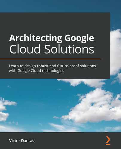
In the GCP console, expand the navigation menu on the left by clicking on the menu icon (the icon with three stacked horizontal lines) in the top-left corner. Then, search for and click on VPC network. Your project likely has a default VPC network, unless you deleted it after creating the project. Explore the default network, observing the subnetworks that were created (one on each of the available regions), and also explore the Firewall section to see the default firewall rules. Finally, check the Routes section to view the local default routes for each subnetwork, plus a default route to the internet. We'll dive deeper into firewalls and routes in the next section.
Click on VPC networks and then on Create VPC Network, as shown in the following screenshot:
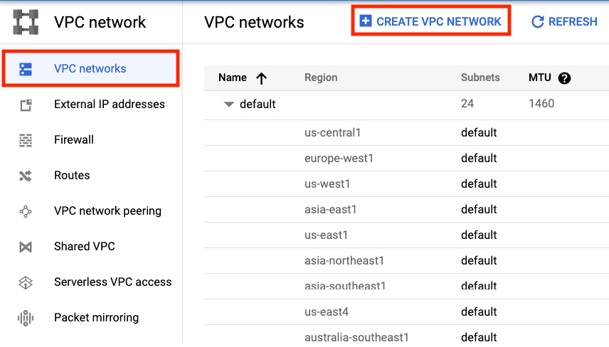
Figure 3.2 – Creating a VPC network
Give it a name (for example, my-custom-vpc), a description if you'd like, and then, under the Subnets section, select Custom under Subnet creation mode. Note that you won't have any subnetworks listed as you would if you'd selected automatic mode because, now, how your subnetworks are defined is up to you.
Click on Add Subnet. Name it subnet1-eastus, and then for Region, select us-east1, and for IP address range, type in 10.10.0.0/20. In the Private Google Access field, select On. Under Flow logs, select On, and then click on Configure Logs to expand the flow logs configuration form. After that, select 30 SEC for Aggregation Interval. Leave the remaining options with their default values. Click on Done.
Click on Add Subnet to add a new subnet. Name it subnet2-westeu. For region, choose europe-west1. In the IP address range field, type in 10.20.0.0/20. This time, select Off for both the Private Google access and Flow logs fields. Click on Done.
Under Dynamic routing mode, select Global. Click on Create. On the VPC networks page, create your newly created VPC (my-custom-vpc). Explore the configuration of your new VPC, which should match the one shown in the following screenshot. Navigate to the Firewall rules tab, as well as the Routes tab, and see how those lists are empty (except for the default route to the internet and to your subnetworks, which were created for you). With custom VPC networks, you don't get certain things automatically set up for you, but you do have full control over the configurations. When designing networks for enterprise organizations, this is the way you should approach it:

Figure 3.3 – A custom VPC network
Now, what did you just create? This is a VPC network with two subnetworks, one located in the East US region and another in the West Europe region. It's a custom VPC network with no default firewall rules. Therefore, no communication is currently allowed in this network. You're starting with tight security. You also have global dynamic routing mode enabled, which means that GCP's Cloud Router has visibility to the resources in all regions and will be able to dynamically route traffic to VMs across different regions. For example, if there's a VPN tunnel set up in one of the regions to an on-premises network, VMs in other regions can only reach the tunnel (and the on-premises network) if global dynamic routing is enabled. In addition, both subnetworks here (and any additional subnetworks that are created) will be advertised by Cloud Router, and all the VMs in all regions will dynamically learn about on-premises hosts, thanks to dynamic routing. To better understand this, take a look at the following diagram, which depicts a VPC network connected to an on-premises network without dynamic global routing:
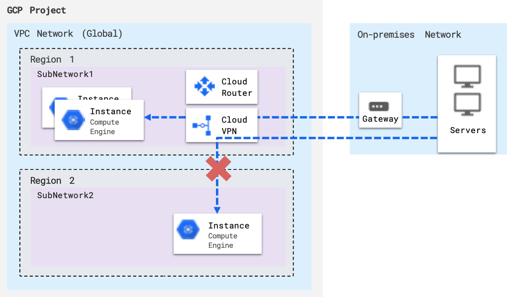
Figure 3.4 – VPC without global dynamic routing
With this regional routing set up, VMs in other regions (different from the one where the VPN tunnel endpoint is) can't be reached by on-premises VMs and aren't able to reach on-premises VMs through the tunnel. They're also not able to learn routes dynamically from the connected on-premises network(s). In other words, without global dynamic routing, your network only "exists" in a single region from the perspective of external networks.
Finally, you enabled Private Google Access and Flow Logs in the East US subnetwork. This means that in this subnetwork, VMs will be able to access Google services and APIs privately (that is, with no need for a public IP address or external access), and a sample of the network flows sent from and received by the VMs in this subnetwork (Flow Logs) will be recorded (every 30 seconds, in our configuration) and be available for use in network monitoring or real-time security analysis. We will explore Flow Logs further in this chapter, but for now, know that this is a crucial network monitoring feature that you can enable at the subnetwork level.
With the basics of networking on GCP out of the way, let's dig into two fundamental elements of any network: routes and firewalls.
Understanding routes and firewalls in Google Cloud
By default, every network in GCP will have routes automatically created to handle reachability between instances in the network (regardless of whether they are on the same subnetwork), and also a default route for traffic leaving the network. The actual network routers along the way are not something you manage or even see. They're entirely abstracted away and treated as a single centralized virtual router, which every instance connects to. Through Google's Cloud Routes service, you can create your own custom routes by defining a next hop IP address for traffic destined to any network you specify (via its IP address range). You can also apply tags to routes so that they only apply to specific instances with the corresponding tag, but otherwise, routes apply to all the instances in the network by default.
The Firewall service in GCP functions as a distributed stateful firewall across the VPC network. This means that firewall rules are applied to the network as a whole, and there's no determining specific interfaces, contexts, or such things as you would do on a traditional physical firewall. Firewall rules are, however, still applied at the instance level and will be evaluated even on traffic between two instances in the same subnetwork. You can think of there being a firewall appliance between any pair of instances in the network, and between any instance and the outside networks.
A firewall rule can explicitly allow or deny traffic, but the VPC firewall implicitly denies all ingress and allows all egress communications. In other words, unless explicitly allowed, any ingress traffic will be denied, and unless explicitly denied, any egress traffic will be allowed.
A firewall rule contains a direction, a type (ingress or egress), one or more sources, one or more destinations (target), a protocol, a port, and an action (allow or deny). The following screenshot shows an example of an ingress rule (on the left) and an egress rule (on the right):

Figure 3.5 – Firewall rule creation example – ingress (left) and egress (right) rules
Zero trust
As the perimeter becomes more "porous" with the expansion of the mobile workforce, a crucial network design consideration is zero trust security. The general idea is never to trust and always verify. It involves a collection of principles and behaviors, one of which is the least privilege principle we discussed previously for access management. Others are to always explicitly verify authentication and authorization requests with all available relevant information, and, most importantly, always assume breach. Assuming breach means you make design and governance decisions while not only thinking about ways you can prevent a breach from happening but also how you can protect the environment when (not if) a breach occurs. From a networking perspective, the best way to achieve this is to implicitly block any network traffic between any pair of servers in the infrastructure and only explicitly allow communications when and where they're needed, as specifically defined as possible. The goal is to minimize lateral movement, or the "blast radius", of a successful attack by preventing the attackers from reaching any other business-critical systems within the network from a source they managed to access. An example of this would be if someone manages to, through whatever means, open a secure shell (SSH) to a seemingly unimportant VM instance, such as a developer machine. There might not be any relevant or critical business data inside that VM – not even an application running inside it. However, imagine if the firewall in the underlying network permits any communication between VMs in the environment, because someone once thought "it's inside our environment, it's a trusted zone." Now, the attacker can essentially "jump" into any other machine (through SSH or other means) and eventually land on a machine containing business-critical intellectual property or sensitive data. Even if SSH or Remote Desktop Protocol (RDP) traffic is blocked and full access to other VMs is prevented, there are other means through which the attacker can obtain information (data exfiltration) or simply cause damage, such as overloading other servers with heavy "dummy" network traffic.
By assuming breach, each request in the network is analyzed as if it could be coming from a compromised server or application or the open internet. Strict security controls are then enforced, regardless of how seemingly harmless an access request may be. A system designed with zero trust security may be more challenging to manage, and it may even hurt business agility at times. But it is likely the best insurance policy a company can have against a security breach event, which, often, businesses cannot recover from.
The implicit deny feature of Google Cloud's Firewall facilitates the zero trust model. For a robust network security foundation, ensure overly permissive firewall rules are never created and that they are periodically reviewed.
Understanding load balancing in Google Cloud
Load balancing is a crucial network function and an important design component as it directly affects the availability and resiliency of a solution. In GCP, load balancing is a fully distributed and software-defined service (this shouldn't come as a surprise to you at this point in this book!). It is not hardware-based, which means no actual physical appliances are being provided, and no infrastructure you have to manage or operate. All load balancing services are fully managed and scale automatically. There are a few different types of load balancing in Google Cloud, all of which we will explore in this section.
Layer 7 HTTP/HTTPS load balancing
Load balancers can be categorized broadly by the layer at which they operate. This "layer" refers to the Open System Interconnection (OSI) model of networking (https://en.wikipedia.org/wiki/OSI_model), which defines seven stacked layers of communication, from the physical layer (layer 1) to the networking layer (layer 4) and all the way "up" to the application layer (layer 7). Because the HTTP protocol is an application layer protocol (hence layer 7), a load balancer that is HTTP-aware is considered to be a layer-7 load balancer (or just simply an HTTP load balancer, since in most cases there are really no other application protocols supported). Most HTTP load balancers also support the more secure HTTPS protocol and therefore can also be referred to as an HTTPS load balancer, or, how Google will typically write it as a catch-all term, an HTTP(S) Load Balancer.
What does it mean for a load balancer to be HTTP(S)-aware? This means that it "understands" the HTTP protocol, and it can therefore deliver features such as URL-based routing decisions, cookie-based session affinity, and SSL offloading. We will elaborate more on these features shortly. In Google Cloud, an HTTP(S) Load Balancer can be of two types: external or internal. Let's see what the differences are.
External HTTP(S) load balancing
In the Premium Network Service Tier, external load balancers are distributed globally and have an external anycast IP address. An anycast IP address means that even though a single IP address has been defined, multiple geographically distributed devices can share this same IP. Based on the location of a user's request, the closest device to the user will be the one that handles the request. So, even though everyone "sees" the same IP address (which simplifies DNS setup), what that address actually maps to in terms of physical infrastructure will correspond to the closest network entry point to that specific user. In the Standard Network Service Tier, external HTTP(S) Load Balancer is a regional service, and its backend instances are required to all be in the same region.
In Google Cloud, an HTTP(S) Load Balancer is a proxy-based load balancer for HTTP and HTTPS protocols that can also authenticate communications by using SSL certificates (in the case of HTTPS). This means unencrypting SSL can be carried out at the load balancer, thus offloading the backend servers from the burden of doing so (this capability is often referred to as SSL offloading). You can also control the features of SSL that your HTTP (S) Load Balancer uses to negotiate and establish HTTPS connections with clients by defining SSL policies. For example, you can enforce a minimum TLS version of 1.2, thus preventing clients from attempting to use the less secure 1.1 or 1.0 versions.
The fact that it is a proxy-based load balancer means that it terminates HTTP(S) connections from clients before reinitiating a connection toward the backend. It can use a global URL map that you define to make a forwarding decision based on HTTP attributes (such as URL, cookies, or protocol headers). For cross-regional load balancing (in the Premium Tier), the HTTP(S) Load Balancer can also intelligently route requests from users to the backend instances in the region that is closest to the users. If the closest region instances don't have available capacity, it will forward to the next nearest region instead. Backend capacity is measured by either CPU utilization or requests per second (RPS). A global health check periodically monitors the backend instances' health to ensure requests are not routed to unavailable servers.
Content-based routing can be configured by using the URL path attribute. For example, the request path may define different types of served contents, such as video (with the /video path) and images (with the /images path), and therefore can be used to route traffic to the right dedicated backend system according to the type of content being requested. For more complex and global use cases, you can have a combination of cross-regional load balancing (making forwarding decisions based on proximity) and content-based routing. An example of such a case is illustrated in the following diagram:

Figure 3.6 – External HTTP(S) Load Balancer with content-based and intelligent global routing
Cloud Armor can be used together with HTTP(S) Load Balancer to add Distributed Denial of Service (DDoS) protection to the frontend and the capability to either blacklist or whitelist a set of IP addresses for access. It also provides filtering based on layer 7 attributes, in addition to layers 3 and 4, thus enabling protection against web-based attacks. Preconfigured Web Application Firewall (WAF) rules can be added to security policies to protect web servers against common attacks such as SQL injection (SQLi) and cross-site scripting (XSS).
An external HTTP(S) Load Balancer can also be configured with a content delivery network (CDN). A CDN leverages globally distributed edge points of presence (PoP) to cache content at locations that are close to end users, thus providing faster access and reduced serving costs. In Google Cloud, this capability is offered through the Cloud CDN service, which uses Google's PoP and CDN nodes to provide global scale caching. You can enable Cloud CDN with a checkbox when setting up an HTTP(S) Load Balancer's backend service.
Consider incorporating both Cloud Armor and Cloud CDN services into your network design for web applications. Cloud Amor is an effective WAF service that will protect your web applications against common attacks, such as those identified in the Open Web Application Security Project (OWASP) Top Ten list (https://owasp.org/www-project-top-ten/). You can also create your own custom rules by applying any combination of filters on the layer 3 through layer 7 parameters of network packets. The cloud CDN service can be "stacked" with Cloud Armor to deliver static content that is less prone to exploitations, while your origin servers (application backend) remains protected for all cache miss events that redirect users to your web servers directly.
Internal HTTP(S) load balancing
The HTTP(S) Load Balancer can also be configured as an internal load balancer; that is, a regional layer 7 load balancer with an internal frontend IP address. The load balancing capabilities are the same as the external load balancers'; the only difference is that, since it's a regional load balancer, it doesn't provide any of the intelligent global routing capabilities that an external load balancer does with an anycast IP address. An internal HTTP(S) Load Balancer can be used internally to distribute load among backend services where HTTP-based load balancing features are needed.
For example, in a three-tiered web service, the Web Tier (frontend web servers) can be scaled using a global, external HTTP(S) Load Balancer, the characteristics of which we explored previously. Then, that HTTP(S) traffic can flow from the Web Tier to an Application Tier, consisting of one or more application backend servers behind one or more regional load balancers. Each regional HTTP(S) Load Balancer provides an internal frontend IP address that's used to distribute traffic to the Application Tier servers based on, for example, HTTP header values. This use case is illustrated in the following diagram:
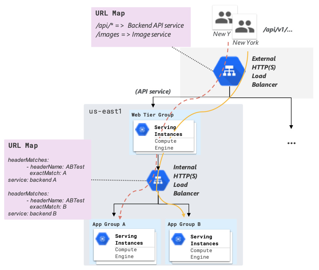
Figure 3.7 – Example use case of an external and internal HTTP(S) Load Balancer
The syntax shown for the URL Map in the preceding diagram is expressed at a high level and does not correspond to the actual syntax you would use, but it illustrates the idea. In this example, the web server located in the region that is closest to the end users will serve the traffic and forward requests to one of two backends: App Group A or App Group B. This routing decision is based on the value of the custom HTTP header, called ABTest. Hence, there are two layers of layer 7 routing in this example: URL-based routing (at the web tier with an external HTTP(S) Load Balancer) and header-based routing (at the application tier with an internal HTTP(S) Load Balancer).
Another use case would be when an application is served only internally, typically for security reasons, to clients on another network that has been peered with (or connected to via a VPN) the VPC network where the application is hosted.
Layer 4 TCP/UDP load balancing
The layer 4 load balancers are not aware of the higher-level protocols such as HTTP, so they only make routing decisions based on IP addresses and ports. Things such as URL maps, content-based routing, and other HTTP-related capabilities are not supported. These load balancers are typically used for more straightforward use cases, usually in internal networks, to distribute loads to a cluster of backend instances. However, they can also be used on public networks with an external frontend IP address, in which case they are referred to in Google Cloud as (external) TCP/UDP Network Load Balancers (or just Network Load Balancers).
External TCP/UDP load balancing
The Network Load Balancer distributes TCP and UDP traffic (any port) across instances in a region and provides an external IP address to the frontend. Unlike the HTTP(S) Load Balancer, these load balancers do not work as proxies but instead as pass-through load balancers. This means that connections are not terminated at the load balancer and reinitiated with the load balancer itself as the source (which would be a normal proxy behavior). Instead, the connections are rerouted to their destination, with the original source IP address preserved. Responses from the backend servers then go directly back to the clients, not through the load balancer. This is referred to as direct server return. In other words, the load balancer transparently forwards the traffic to a healthy backend instance and then "gets out of the way." As a layer 4 load balancer, it doesn't inspect packets beyond the network layer and thus does not "read" HTTP headers or application-level protocol details. The Network Load Balancer cannot decrypt SSL traffic, but it has no problem forwarding it (for the backend servers to decrypt themselves).
Internal TCP/UDP load balancing
An internal TCP/UDP Load Balancer has basically the same features and characteristics as the Network Load Balancer, with the main difference being that it only supports an internal IP address as the frontend. It is also a regional, pass-through load balancer that operates at layer 4, with direct server return. It is most commonly used to provide load distribution and internal high availability for backend servers. Both external and internal TCP/UDP Load Balancers work with any TCP/UDP ports.
External SSL proxy and TCP proxy
An alternative to the HTTP(S) Load Balancer for non-HTTP applications that still require a more advanced, proxy-based load balancer (potentially capable of SSL offloading) are SSL Proxy and TCP Proxy Load Balancers.
With SSL Proxy Load Balancing, you can terminate user SSL connections at the load balancing layer if your application uses TLS encryption along with an application protocol other than HTTP. For HTTP applications, the HTTP(S) Load Balancer would be the best fit. With the Premium Network Tier, an SSL Proxy Load Balancer can be deployed globally to deliver traffic across multiple regions, with the capability of directing user traffic to their closest region. The SSL Proxy Load Balancing service doesn't work with all TCP ports but with a set list of ports, all of which you can check out by referring to the documentation page: https://cloud.google.com/load-balancing/docs/ssl. You can also define your own set of SSL policies, and you can either use your own SSL certificates or Google-managed certificates (in which case, you're required to use port 443 for the frontend).
Don't need SSL encryption with your non-HTTP application, but still need an external proxy-type load balancer? The TCP Proxy Load Balancing service is the right choice here. It's very similar to the SSL Proxy offering, apart from the lack of support for SSL. It includes the same intelligent global routing (in the Premium Network Tier), proxy-based load balancing behavior, and it has a similarly restricted list of supported TCP ports, all of which you can find here: https://cloud.google.com/load-balancing/docs/tcp.
Design considerations for load balancing
With so many different types of load balancing services in Google Cloud, things can get confusing when you're designing a load balancing solution. However, by understanding how the different load balancing types meet your particular needs, choosing the right one(s) for your design becomes an easier task. The following flowchart consolidates what you've learned so far and should help you do so:
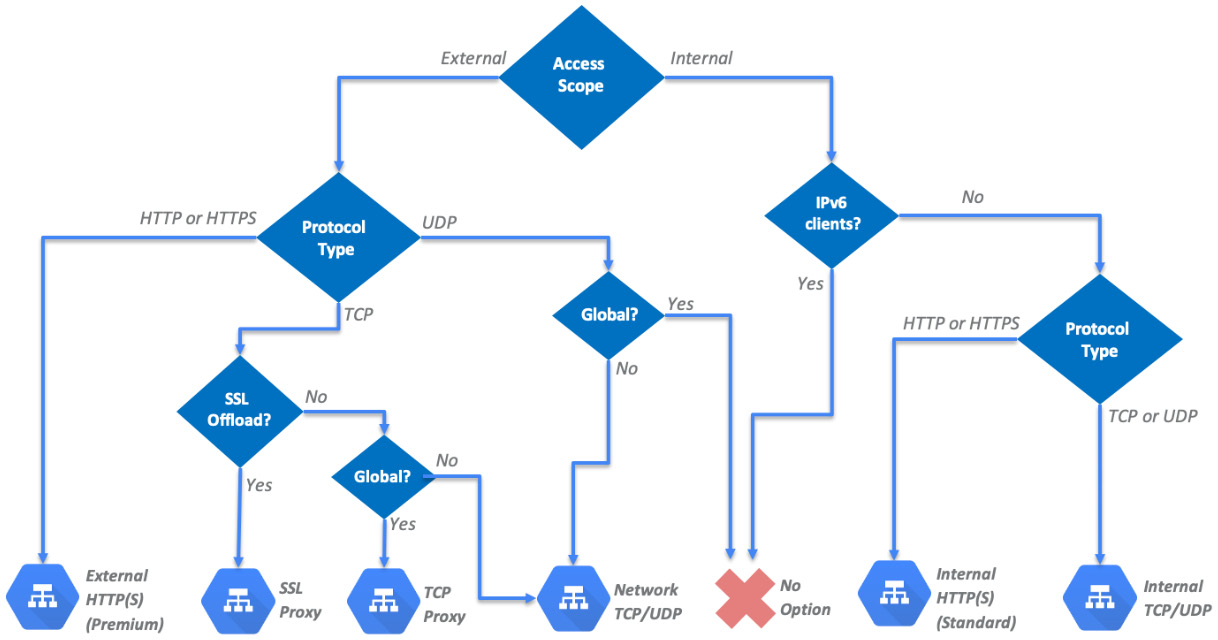
Figure 3.8 – Choosing the right load balancer
Note that IPv6 clients are only supported by the proxy load balancers, which are external load balancers by design. This is why a decision point was included in the flowchart, to account for that limitation. You may have noticed that Internal load balancers with IPv6 client support and global UDP load balancers are two service requirements that don't lead to any available option on GCP.
When designing a load balancing solution for your application, the first question is whether the service should be global or regional, which will also raise the question of which network service tier you should opt for. Then, you can start thinking about what type of network protocol the application(s) will use, whether SSL offloading is a required or advantageous feature, and potentially whether IPv6 clients should be considered. Remember, no matter what option you choose, high availability and scalability will be built into the solution, and it's not something you have to design for yourself (when it comes to the load balancer itself).
So far, you've learned about the basics of networking in Google Cloud and networking services such as routing, firewalls, and load balancing. You probably have a good enough foundation for designing cloud-native solutions using GCP. However, it is often the case that your VPC networks need to be connected to one or more on-premises networks. This could be due to an ongoing cloud migration, where certain services are still only available on-premises, or due to security and compliance requirements that dictate certain services and/or data must remain on an on-premises infrastructure. For these scenarios, you will need to design a hybrid connectivity strategy, the options for which we shall explore next.
Designing for hybrid connectivity
There are mainly three factors that influence which hybrid connectivity service we choose: bandwidth, reliability, and security. The options range from a Virtual Private Network (VPN) connection to direct fiber connectivity to Google's network.
Cloud VPN
Google Cloud's VPN service is Cloud VPN, which provides an Internet Protocol Security (IPSec) tunnel endpoint in your VPC networks, to which you can establish VPN connections from an on-premises (or another cloud's) network via its VPN gateway. A VPN connection is established over public networks (that is, over the internet), though this is often unreliable and has no service-level guarantees. Public networks are also generally unsecure, but the VPN service encrypts traffic between the two gateways with the IPSec protocol, thus overcoming, to some extent, the lack of security in public networks.
Google Cloud offers two types of cloud VPN gateways:
- HA VPN: This is a high availability (HA) VPN solution that provides an SLA of 99.99% service availability (only on the Google Cloud side of the connection). This works because the VPN gateway in this offering will have two interfaces (with two external IP addresses) to set up two redundant VPN tunnels, which helps overcome the unreliable nature of public networks by establishing a backup tunnel in case one fails. For achieving end-to-end reliability, the peer VPN gateway device must support dynamic BGP routing and be configured with adequate redundancy.
- Classic VPN: Classic VPN gateways have a single interface and external IP address and are able to deploy a single tunnel to the same peer gateway. Tunnels can use either dynamic BGP routing or static routing (which can be policy-based or route-based, with the latter being the most common option). This service provides a lower SLA availability of 99.9%.
Each cloud VPN tunnel supports up to 3 G bps (gigabits per second) total bandwidth for ingress and egress traffic. Since 1 byte equals 8 bits, this is equivalent to 375 MBps (megabytes per second). Due to the reliance on public network infrastructure, the actual bandwidth of a VPN connection can oscillate, and performance can be unstable at times.
Cloud Interconnect
For organizations willing to pay for a slightly more reliable connection and higher bandwidth with more stable performance, the options to consider are the Cloud Interconnect services: Partner Interconnect and Dedicated Interconnect.
Partner Interconnect
This service provides connectivity between an on-premises network and a Google Cloud VPC network through a partner service provider. Suppose your on-premises data center is at a physical location that can reach a colocation facility where a partner is present through a peering edge. In that case, you can work with that service provider to establish connectivity between their network and your on-premises network. Supported service providers will have existing (physical) network connections to Google's network, so only your "side" of the connection needs to be set up.
Depending on the partner service provider's available offerings, you can configure either layer 2 or layer 3 network connectivity. With a layer 2 connection, you establish a BGP session between Google Cloud (via the Cloud Router service on GCP) and on-premises routers for each VLAN attachment you create. For layer 3 connections, the service provider will establish a BGP session between your Cloud Router and their edge routers for each VLAN attachment, and you don't need to configure BGP yourself on your on-premises router.
Google has two prescriptive configurations for Partner Interconnect: one for 99.99% availability (recommended for production environments) and another for 99.9% availability (for less mission-critical applications). These SLAs do not apply to connectivity between your network and the service provider's, but between the service providers and Google Cloud. Information on how to configure your Partner Interconnect topology for 99.99% availability is available at https://cloud.google.com/network-connectivity/docs/interconnect/concepts/partner-overview#9999_availability_recommended.
Network bandwidth for this type of connection ranges from 50 Mbps to 10 Gbps. Availability and prices vary by service provider.
Dedicated Interconnect
As the name implies, this dedicated connectivity service does not require a partner service provider and instead provides direct physical connections between an on-premises network and Google's network. For this to be possible, however, the on-premises network must physically reach Google's network at a colocation facility. The on-premises network devices must also support specific technical requirements for enabling 10G or 100G fiber-based circuits. A detailed list of requirements can be found at https://cloud.google.com/network-connectivity/docs/interconnect/concepts/dedicated-overview#before_you_use.
Similar to the Partner Interconnect service, there are two different configurations for achieving either 99.99% or 99.9% availability. For instructions on how to set up a redundant topology for 99.99% availability, please refer to https://cloud.google.com/network-connectivity/docs/interconnect/tutorials/dedicated-creating-9999-availability.
The available bandwidth for a Dedicated Interconnect connection can be 10 Gbps or 100 Gbps per link.
Cloud peering
Cloud peering offerings (not to be confused with VPC peering) allow you to have a direct (with direct peering) or partner-based (with carrier peering) link between your business network and Google's edge network. This capability exists outside of Google Cloud and is tailored for businesses that wish to access Google Workspace (formerly G Suite) applications at high throughput.
You should consider including one of these services in your design when working with organizations that rely heavily on Google Workspace applications.
Choosing a hybrid connectivity option
To highlight the differences between the different hybrid connectivity offerings and help you decide which option is best for your solution, take a look at the following comparison table:


You should now be familiar with Google Cloud's networking services and things such as routing, firewalls, and load balancing on GCP. You should also have the foundational knowledge to design a network in Google Cloud and design a hybrid connectivity solution. Still, you may be feeling that designing a network sounds like a daunting task, and that's because it is. In the next section, we will look into a few standard network designs and some best practices that will give you some references to lean on when architecting networks in Google Cloud.
Mastering common network designs
In this section, we're going to cover some design considerations and best practices, followed by common designs, for VPC deployments on GCP.
Design considerations and best practices
The network is one of the most fundamental components of an IT infrastructure. For that reason, the design of the VPC network should be given sufficient time and effort in the early stages of the overall solution design. Design decisions at this level can't be easily reversed later, so make sure you're taking in as much input as possible into consideration.
In this final section of this chapter, you're going to learn about the common design patterns you can use to build your own design. But before that, we will highlight a few best practices to keep in mind and guide you through your decisions.
Use a naming convention
This goes for all your resources and not only the network-related ones. But if you're starting your design with the network (a natural starting point), that may be the time to set your naming convention straight. This involves defining how resource names are constructed and setting abbreviations, acronyms, and relevant labels that help users identify a resource's purpose and its associated business unit and location. Some examples of labels you may need to define are as follows:
- Company short name: acm (ACME)
- Department or Business Unit: it, hr, and so on
- Application code: crm (Customer Relationship Management application), pay (Payroll application)
- Region abbreviation: eu-we1 (europe-west1), us-ea2 (us-east2)
- Environment: dev, test, prod, and so on
Once you have defined some labels and possible values based on your IT environment, you can start defining naming structures for various GCP resources; for example:
- Department-specific and global network resources: {company name}-{dept-label}-{environment-label}-{resource type}-{seq#}. For example, if you have one VPC per company department, you apply this to your VPCs; for example, acm-it-test-vpc-1.
- Department- or application-specific regional/zonal resources: {company name}-{[APP or DEPT] label}-{region/zone label}-{environment-label}-{resource type}-{seq#}; for example, applied to subnetworks: acm-hr-eu-we1-prod-subnet-01. A naming convention will help ensure consistency in how resources are named and will facilitate several aspects of infrastructure management.
Subnetwork design
Firstly, as we mentioned previously, avoid using default or auto mode networks and opt for custom mode networks instead so that you have full control over the subnetwork design and firewall rules. Then, you can deploy subnetworks in the regions that your business operates in and adopt an IP address scheme so that there are no overlaps with any other network (such as on-premises networks) that you intend to peer or integrate with your VPC network.
Also, aim to group your applications into a few, large subnetworks. Traditional enterprise networks separate applications into many small address ranges (by using, for example, VLANs). However, in modern cloud networks, fewer subnets with large address spaces are recommended as it facilitates management and reduces complexity at no cost in terms of security. Firewalls, service accounts, and network tags are all features that can be used to segment traffic and isolate network communications as needed.
Shared VPC for multiple projects
If you're designing a multi-project solution in GCP, you may want to consider deploying a shared VPC. As we discussed previously, a shared VPC offers an effective way for you to simplify management and centralize security and network policies in a single host project. In contrast, service projects (which may represent, for example, different company departments or applications) can simply deploy their resources to the same network. This avoids the situation where there are multiple VPC networks to manage, which increases the risks of inconsistent configuration and policies, excessive use of network administration roles, and disruptive changes to the network design.
In terms of the service projects, grant the network user role at the subnetwork level so that each project can only use its assigned subnetwork(s), which will reinforce the principle of least privilege.
Isolate workloads
For isolation between project-specific workloads and for independent IAM controls, you can create VPC networks in different projects. Network-related IAM roles assigned at the project level will apply to all VPC networks within the project, so if you require independent IAM policies per VPC network, create different projects to host those networks. This setup works as an alternative to or in conjunction with a shared VPC model.
If you're working with an organization that deals with compliance regulations (such as HIPAA or PCI-DSS) and sensitive data that needs to be secured appropriately, then isolate these types of data into dedicated VPC networks. Two different VPC networks in GCP will never be able to reach each other (from a routing perspective) unless they're peered (or are integrated by other means, such as with a VPN gateway or a network appliance). This significantly reduces the risk of unauthorized access to the data or breach of compliance.
Limit external access
Limit the use of external IP addresses and access to public networks as much as possible. Resources with only an internal IP address can still access many Google services and APIs through Private Google Access. You can use a Cloud NAT to provide VMs with external access. By limiting unnecessary external access, you reduce the attack surface on your environment by eliminating the possibility of VMs being reached from external sources (especially when management protocols such as SSH and RDP are not restricted at the firewall level).
Common network designs
In this section, we will look at some of the common network designs that are adopted by enterprises using Google Cloud.
Single VPC network, high availability
A single VPC network, which can be of global scale in Google Cloud, can, in many cases, suffice if you wish to build a robust network design that is easy to manage and maintain. There are two ways of obtaining high availability with a single VPC network:
- Leveraging different zones within a subnetwork: By deploying instances to different zones within a subnetwork (and its associated region), you spread your application across different infrastructure failure domains, therefore obtaining improved availability and resiliency against hardware failures (and, in some cases, even the failure of an entire data center).
- Leveraging different regions (with different subnetworks): Deploying instances to different regions allows you to obtain a higher degree of failure independence, which even protects you against regional failures and natural disasters. It's the best design choice for realizing robust global systems. With a global HTTP(S) Load Balancer, you can deliver lower latency for end users with intelligent global routing, as you learned previously.
Whether you opt for multi-zonal or multi-regional deployments on the network, you can obtain high availability without additional security complexity (it's still one single GCP firewall for the network). The following diagram illustrates this design:

Figure 3.9 – Single VPC network with zonal and regional deployments
In the preceding diagram, VM instance Instance1B is a failover instance for Instance1A on a different zone that can serve traffic in case Instance1A fails to. VM Instance1C is a failover instance located in a different region.
Shared VPC and multiple service projects
For a more complex and scalable infrastructure, you can opt for having a shared VPC where network controls can be centralized (that is, the configuration of things such as subnetworks, routes, and firewall rules), with service projects able to share the same network infrastructure. The users in these service projects still have the autonomy to deploy and manage instances and applications, without the risk of impacting the network configuration. This is a great way to prevent breaking changes and inconsistencies in the network configurations.
This design is exemplified in the following diagram:
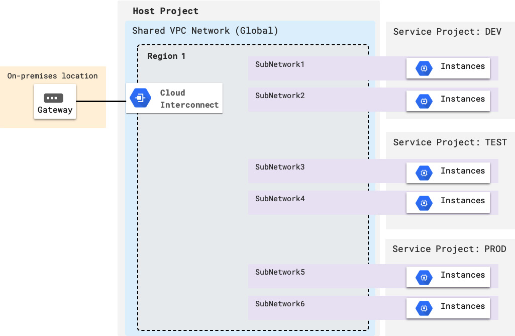
Figure 3.10 – Shared VPC and multiple service projects
Only one region is shown in the preceding diagram, but it easily works with multiple regions as well. Subnetworks 1 and 2 are shared with the DEV service project (as you learned previously, you can define which specific subnetworks are shared with which specific service projects). Subnetworks 3 and 4 are used by the TEST project, while 5 and 6 are used by the PROD project. Network policies are centralized in the host project. Workloads and VM instances are managed within each of the service projects individually, and they can be deployed to the subnetworks that are created in the host project.
Multiple VPC networks bridged by a next-generation firewall (NGFW) appliance
Sometimes, security requirements will dictate that "untrusted" network environments (the portion of the network that's exposed to the internet or outside networks) be more strictly isolated from "trusted" networks (such as the internal networks hosting applications) via a next-generation firewall (NGFW). Google Cloud's native firewall is not an NGFW firewall, the definition of which is a firewall with additional network filtering functions such as deep packet inspection. An NGFW provides you with deeper insights into the packets traversing the network, thus allowing you to detect and prevent network attacks. However, while you lack such capabilities from GCP's built-in firewall service, nothing prevents you from deploying a VM appliance containing a software-based version of an NGFW (several vendors make VM images available for consumption in the cloud).
In this design, an untrusted network (DMZ) is introduced to terminate outside connections (such as hybrid interconnects and connections originating from the internet). The traffic is then filtered in the NGFW, which is deployed to a multi-NIC VM, before reaching trusted networks. The NGFW VM has an NIC on each of the VPC networks, which, in this design, must all reside within the same GCP project. Therefore, you should observe the limits on the number of VPC networks and, most importantly, on the number of NICs supported on a single VM (since the former can be extended upon demand, but the latter has a hard limit of eight as the time of writing).
There are many variations of this design, but the following diagram shows an example of such a topology:
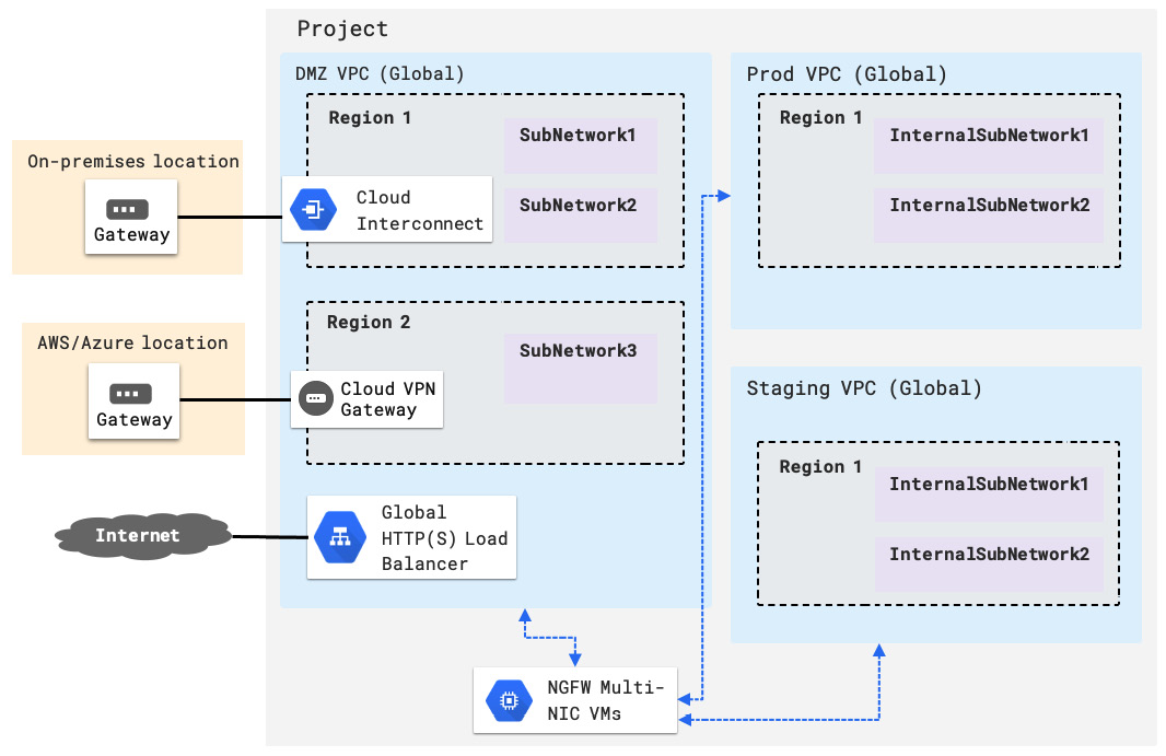
Figure 3.11 – Multiple VPC networks bridged by an NGFW appliance
In a topology diagram, a DMZ VPC is where external traffic is terminated. In this example, this is traffic from an on-premises location, from another public cloud network, and the internet. This is the "untrusted" network. Two other trusted networks, Prod and Staging, represent a production VPC network and a staging VPC network where application instances are deployed to, respectively. Traffic from and to the untrusted zone is filtered through the NGFW firewall.
You could combine this design with that of a shared VPC and service projects so that if you have multiple projects, you won't need to replicate this design over to different projects (which would require numerous NGFW appliances and licenses). For example, the project shown in Figure 3.8 would become a host project, with the two trusted VPCs being shared with other service projects (used, for example, by different development teams).
Summary
In this chapter, you have learned about the network services in Google Cloud, how to handle routes and firewall rules, and how to make design decisions around load balancing and hybrid connectivity using GCP. You have also learned some best practices and common network designs, and, very importantly, about the zero trust principle. There is one big takeaway from this chapter: never trust, always verify. The skills you've learned in this chapter will allow you to bake security into your network design, incorporate the right type of load balancing based on your application needs, and make sure multi-project cloud solutions have a centralized, shared VPC, where network policies are set and controlled from one place.
You should now have a robust foundation to start designing networks in Google Cloud that are global, scalable, and able to offer a resilient and secure infrastructure environment for VMs to be deployed on.
Speaking of which, in the next chapter, you will learn how to architect a compute infrastructure using Google Cloud's compute services (such as VMs, App Engine, Cloud Functions, Cloud Run, and Kubernetes Engine).