


IBM AIX Geographic Logical Volume Manager best practices for Cloud deployments
This chapter introduces IBM AIX Geographic Logical Volume Manager (GLVM) concepts and operations. It also provides best practice recommendations for cloud deployments by using GLVM.
This chapter includes the following topics:
1.1 Introduction
As more companies evolve to the use of a hybrid computing mode in which some of their applications run on-premises and other in one or more commercial data centers (or clouds), problems can arise when these two environments want to share data.
Currently, the only common connection type that is supported is IP. Also, storage mirroring in public cloud environments often is not possible because of scaling and multi-tenant management restrictions. Although this issue is not such a concern if the application supports replication over IP (for example, databases, such as IBM DB2®, Oracle, and SAP HANA), it is an issue for most other applications.
Options are available for Disaster Recovery (DR) management in the cloud for Power Systems for each operating system, including the following example:
•AIX: An administrator can use IP-based GLVM mirroring or one of the database mirroring mechanisms (such as IBM Db2® HADR and Oracle Data ZGuard).
•IBM i: An administrator can use PowerHA SystemMirror for IBM i with Geo Mirroring or a third-party solution for replication.
This document focuses only on AIX GLVM as the basis for a DR solution. GLVM can be used in the cloud in pure public and hybrid deployment models, as shown in Figure 1-1.

Figure 1-1 Two types of cloud deployments
AIX supported IP replication of data volumes for some time. First, GeoRM was supported, which was part of HAGeo. Then, in 2008, AIX supported synchronous and asynchronous replication of logical volumes over IP by way of GLVM. This support meant that a file system or raw logical volume can be replicated to a remote system with no restriction imposed by the choice of database or the application that is used.
This publication shows how to create an AIX Volume Group that spans LUNs that are attached to your local system and to your LPAR in another data center or in the IBM Cloud®. Although geographically mirrored volume group (GMVG) can support up to three copies, GLVM supports two sites only; therefore, only one site can have two copies of the mirror.
This configuration is common where the customer wants to avoid moving the application to another site if they experience an outage because of a failure of one copy of the local storage. It is also possible to have multiple servers at each site to provide greater availability; however, only one server can access the data on the disks at one time without PowerHA SystemMirror.
In addition to mirroring data between data centers, GLVM can be used to mirror data between a data center and the cloud or between clouds.
Although GLVM is part of AIX and requires no extra licensing for a basic configuration, PowerHA SystemMirror Enterprise Edition is required and recommended to monitor the environment and to automate the management of GLVM and the applications.
|
Note: Without PowerHA SystemMirror, AIX cannot monitor the state of either site; therefore, it also cannot control the state or mode of the GLVM daemons. As a result, it is a manual process, with no checks to prevent the corruption or loss of data.
It is highly recommended that GLVM be deployed with PowerHA SystemMirror for AIX Enterprise Edition. PowerHA SystemMirror not only provides a robust workload stack HA management, it also handles many errors in the environment and helps recover asynchronous GLVM better. PowerHA SystemMirror also provides interfaces for easy setup of asynchronous GLVM and disk management.
|
All the tuning and design recommendations in this book apply equally to a GLVM stand-alone configuration, or one managed by IBM PowerHA SystemMirror. This publication also provides guidance regarding GLVM cloud deployments, whether private, public, or hybrid.
|
Note: All measurements and performance numbers that are quoted in this publication are based on a laboratory environment or controlled conditions. Because GLVM performance depends on many AIX tunables (for example: storage and network performance tunables) and environment variables (for example: network speed, quality, and latency) it requires an assessment for your specific environment to be accurate. The numbers that are quoted in this publication are for illustrative purposes only.
IBM Techline offers an at-cost service to assess your AIX workload environment and the CPU and memory usage. This assessment can help better plan for GLVM deployment. You also can engage IBM Lab Services or a qualified Business Partner if you need to plan and deploy GLVM.
|
1.2 Geographic Logical Volume Manager concepts
At a high level, GLVM provides a pseudo-physical volume or volumes, which are treated by the AIX LVM as standard physical volumes and can be added to a volume group with local physical volumes. In reality, each is only a local logical representation of the remote physical volume.
On the remote system, where the physical volume is installed, a Remote Physical Volume (RPV) Server is used for each replicated physical volume. On the local system, a device driver is used for each pseudo-physical volume, which is called the RPV client.
The AIX LVM manages the reads and writes for the pseudo-physical volumes, and the RPV client and Server pair manages the transfer of this data to the physical volume over the network.
1.2.1 Summary
GLVM provides software-based mirroring between two AIX systems over an IP network to protect against loss of data from the active site. GLVM works with any disk type that is supported by AIX LVM. The same type of disk subsystem does not need to be used at the source and destination, just as the AIX LVM can mirror between two different disk subsystems locally. GLVM also has no dependency on the type of data being mirrored and supports file systems and raw logical volumes.
The distance between the sites is limited only by the acceptable latency (for synchronous configurations) or by the size of the cache (for asynchronous configurations). For asynchronous replication, the size of the cache represents the maximum acceptable amount of data that can be lost in a disaster.
|
Note: GLVM is not supported for mirroring the rootvg.
|
To mirror your data across two sites, configure a volume group that contains local and remote physical volumes. This configuration is called a GMVG.
1.2.2 Remote physical volume
A remote physical volume (RPV) consists of the following components:
•The RPV client
The RPV client is a pseudo-device driver that runs on the active server or site; for example, where the volume group was activated. One RPV client is available for each physical volume on the remote server or site (called hdisk#). The LVM sees it as a disk and performs the I/Os against this device. The RPV client definition includes the remote server address and timeout values.
•The RPV server
The RPV server is an instance of the kernel extension of the RPV device driver that runs on the node on the remote server or site; that is, on the node that includes the physical volume. The RPV server receives and handles the I/O requests from the RPV client.
One RPV server is available for each replicated physical volume and is called rpvserver#.
One RPV server is available for each replicated physical volume and is called rpvserver#.
•The GLVM Cache
This special logical volume is of the type aio_cache that is designed for use in asynchronous mode GLVM. For asynchronous mode, rather than waiting for the write to be performed on the remote physical volume, the write is recorded on the local cache, and then acknowledgment is returned to the application. At some later time, the I/Os that are recorded in the cache are played in order against the remote disks and then, deleted from the cache after it is successful (acknowledged).
Creating the aio_cache logical volume is shown in Figure 1-2.

Figure 1-2 Cache logical volume for Asynchronous mode
•Geographic Mirrored Volume Group
This AIX Volume Group contains local physical volumes and RPV clients (see Figure 1-3 on page 6). You can mirror your data between two sites by configuring volume groups that contain local physical disks and RPVs.
With an RPV device driver, the LVM does not distinguish between local and remote physical volumes. Instead, it maintains mirror copies of the data and is, usually, unaware that some disks are at a remote site.
For PowerHA SystemMirror installations, the GMVGs can be added to resource groups and then managed and monitored by PowerHA SystemMirror.

Figure 1-3 GLVM synchronous operation
1.2.3 AIX LVM Mirror Pools
Although mirror pools are not restricted to use solely with GLVM, mirror pools are required for asynchronous replication and recommend for synchronous. All mirror pools are a way to divide the physical volumes in a volume group into distinct groups or pools and then tightly control the placement of each logical partition’s mirrored copies.
Mirror pools were introduced in AIX 6.1.1.0 and apply only to scalable volume groups. Mirror pool names must be fewer than 15 characters and are unique within a volume group.
A mirror pool consists of one or more physical volumes and each physical volume can belong only to one mirror pool at a time. When defining a logical volume, each copy of the logical volume can be assigned to a specific mirror pool. This definition ensures that when a copy of a logical volume is assigned to a mirror pool, partitions are allocated only from physical volumes in that pool.
Before mirror pools were introduced, the only way that logical volumes were extended and that it was ensured that partitions were allocated from the correct physical volume was to use a map file. Physical volumes can be assigned to a mirror pool by using the chpv or the extendvg commands.
No more than three mirror pools can be used in each volume group. Each mirror pool must contain at least one complete copy of each mirrored logical volume that is defined in that pool.
|
Note: After mirror pools are defined, the volume group can no longer be imported into versions of AIX before AIX 6.1.1.0.
Also, if enhanced concurrent mode volume groups are used, all nodes in the cluster also must be greater than AIX 6.1.1.0.
|
Mirror pool strictness can be used to enforce tighter restrictions on the allocation of partitions in mirror pools. Mirror pool strictness can include one of the following values:
•Off : This value is the default setting and no restrictions apply to the use of the mirror pools.
•On : Each mirrored logical volume that is created in the volume group must have all copies assigned to mirror pools.
•Super : This value is specifically for GLVM and ensures that local and remote physical volumes cannot be assigned to the same mirror pool.
Although mirror pool characteristics can be changed, any changes do not affect allocated partitions. Therefore, it is recommended to use the reorgvg command after any mirror pool changes so that allocated partitions can be moved to conform to the new mirror pool restrictions.
|
Note: AIX LVM Mirror Pools also are recommended for synchronous mode, but are required for asynchronous mode.
|
This mirror pools are used to ensure that each site includes a complete copy of each mirrored logical volume in the GMVG and the cache-logical volume for asynchronous GMVGs are configured and managed correctly.
1.2.4 Replication modes
GLVM supports two modes of replication: synchronous and asynchronous. It also is possible to configure your environment to use synchronous replication in one direction and asynchronous in the other direction.
Synchronous
This mode was the first mode that was supported on AIX. Writes to a synchronous GMVG are not complete until the remote copy acknowledges the successful write, as shown in Figure 1-3 on page 6. This mode often is impractical, except for configurations where the two sites are typically within 100 km (62 miles), depending on the latency requirements of the application.
Asynchronous
In this mode, writes are cached locally in a special logical volume in the same volume group and then marked as complete. Over time, the changes that are recorded in the cache are played against the remote copy and then, removed from the cache when the remote site acknowledges the change.
Although this mode is much less sensitive to the latency, it is limited by the size of the cache, remembering that the cache also represents the amount of data you can afford to lose in a disaster. This mode must be balanced against the cache being too small because if the cache fills up, all I/O is suspended until space is cleared in the cache.
|
Note: The size of the cache is based on what is required to manage the application’s peak workload. Tools, such as rpvstat, can be used to monitor the number of times the cache fills up.
|
The size of the cache also affects the amount of time that is taken during a move of the application from one site to the other. That time changes which copy of the GLVM is active because the application cannot start until all the outstanding writes from the previous active site are synchronized with the local copy.
Consider the following points about GLVM mirroring:
•Does not depend on the type of database and file system. Applications do not need to be modified to use GLVM mirroring capabilities.
•Does not require the same disk subsystem at each site. Storage at either site can be any storage that is supported by AIX.
•Performs the data mirroring over standard Internet Protocol networks without depending on the specific data that is being mirrored. Therefore, is ideal for cloud environments.
•Is often less expensive than hardware-based mirroring solutions and does not require the same vendors storage at source and destination.
•Uses the mirroring function of the AIX LVM and operates as a layer under the LVM.
•The read preference can be configured to favor the local copy (when available) to maximize performance.
•During a write, the LVM and RPV device driver work together to allow the application to perform a single logical write, which results in multiple writes to the local and remote physical volumes that make up the GMVG.
1.2.5 I/O paths for GLVM replication
This section compares the I/O paths for synchronous and asynchronous modes.
Synchronous mode
Assuming that no stale partitions exist, read operation is defined by the logical volume configuration; that is, the scheduling policy or, if defined, the preferred read. The preferred read must be set to the local copy of the mirror.
For writes, the application writes down through the LVM, which sends the write to both mirror copies, the local physical volume, and the RPV client device driver (the pseudo hdisk), as shown in Figure 1-4.
<
Figure 1-4 Synchronous mode I/O path
After the local physical volume returns I/O complete, the LVM waits until the other mirror write is completed. The RPV client transfers the I/O over the network to the matching RPV server on the remote node, which performs the same write on its local physical volume. After this process is completed, the acknowledgment is sent back by way of the RPV client to the LVM. The local copy often is completed and an acknowledgment can now return to the application.
Asynchronous mode
As with synchronous mode GLVM, read operations follow the LV policy; however, writes are more complex and rely on the existence of a local cache and the use of mirror pools. The use of asynchronous mode allows control to be returned to the application after the write completes on the local physical volume and the local cache. This mode improves application response time, but also increases the amount of data that potentially is lost in a disaster.
Asynchronous mode has stricter requirements and requires the use of mirror pools. The cache-logical volume of type aio_cache also is available and must be created for each mirror pool.
In a GLVM design, the aio_cache in the mirror pool at Site A (aio_cachelv1) is the cache that is associated with Site B because it contains the outstanding data updates for the logical volumes at Site B and vice versa for aio_cachelv2 (see Figure 1-5).

Figure 1-5 Asynchronous cache in each mirror pool
For local writes, the application passes the write to the LVM; then, the LVM passes the write to the physical disk device driver and the RPV client. When the physical volume I/O is complete, the LVM is updated and waits for the RPV client to complete. Meanwhile, the RPV client updates the cache with the write. When that completes, it updates the LVM. The LVM then returns control to the application (see Figure 1-6).

Figure 1-6 Asynchronous mode-local write
Some time later, when the network bandwidth allows, the RPV client checks for the next record in the cache, passes the I/O to the RPV server, which updates the remote physical volume with the write, then returns a completed response to the RPV client.
The RPV client then deletes the record from the cache (see Figure 1-7).

Figure 1-7 Asynchronous write, updating the remote physical volume
1.2.6 GLVM operation
At a high level, the GLVM configuration is the same for asynchronous and synchronous modes of operation. For example, in a single GMVG (glvm_vg), which is made up of physical volumes hdisk4 at site A and hdisk3 at site B, the volume group is created at one site by using the local physical volumes and the remote physical volumes.
Figure 1-8 shows the flow when site A is active.

Figure 1-8 GMVG active at Site A
|
Note: Although the figures in this document show a single logical network that is connecting the sites, GLVM supports up to four separate physical networks, over which the RPV server traffic is striped. It is recommended that each network has similar bandwidth and latency while following different physical paths for availability.
|
Figure 1-9 shows the flow when the direction is reversed and the volume group is activated on site B.

Figure 1-9 GMVG active at Site B
More complex scenarios
If the configuration requires more than one physical volume, a separate RPV server and RPV client are used for each mirrored physical volume, as shown in Figure 1-10.

Figure 1-10 GMVG consisting of two mirrored physical volumes
Two copies of the volume group can exist at one site, as shown in Figure 1-11.

Figure 1-11 GMVG with two copies at Site A
Figure 1-12 shows a more complex HADR scenario with two nodes and two copies that are shared at the primary site, and one node and one copy at the DR site.

Figure 1-12 HADR configuration
1.2.7 GLVM standalone
You can configure geographically mirrored volume groups in AIX GLVM without installing and configuring a PowerHA SystemMirror cluster. The AIX GLVM technology provides the same geographic data mirroring functions as GLVM for PowerHA SystemMirror Enterprise Edition, only without the automated monitoring and recovery that is provided by PowerHA SystemMirror.
PowerHA SystemMirror features
PowerHA SystemMirror introduced the following features:
•Provides automatic detection and response to site and network failures in the geographic cluster without user intervention.
•Performs automatic site takeover and recovery and keeps mission-critical applications highly available through application fallover and monitoring.
•Allows for simplified configuration of volume groups, logical volumes, and resource groups. Supports standard or enhanced concurrent volume groups that are geographically mirrored.
•Uses up to four Internet Protocol networks for remote mirroring. IP traffic is striped across the networks.
•Supports concurrent access configurations, which allow all of the nodes at one site to concurrently access the geographically mirrored volume groups. This feature is supported at one site only; therefore, concurrent access from nodes at both sites cannot exist.
•Controls the preferred read policy that is based on the site.
•The PowerHA SystemMirror GUI:
– Allows the user to dynamically update the size of the asynchronous cache.
– Collects and displays GLVM statistics. Stand-alone users can configure options, such as Grafana and InfluxDB, as discussed in 1.4, “Performance analysis” on page 37.
1.2.8 GLVM resource requirements
No fixed set of resources requirement can be specified for GLVM deployments. Many factors help administrators to decide on the resources that must be set aside for mirroring purposes.
This section provides guidance about what must be measured to plan for GLVM, especially for an asynchronous deployment.
Because GLVM relies on having sufficient resources (CPU, memory, disk, network, and so on), and if any of these resources are insufficient, mirroring does not operate correctly. This section describes the guidelines that can be used to test and deploy various scenarios.
|
Note: Too many variables are involved in sizing GLVM (especially asynchronous) to provide prescriptive equations here.
|
However, the following key variables in all GLVM configurations also vary widely between environments:
•Workload: The type of workload and what or when peak data is being generated must be examined and understood. Peaks in workload compete with GLVM for system resources. This issue can cause congestion and bottlenecks in any of these resource lanes. Customers have a comprehensive set of AIX tools, such as vmstat, topas, iostat, and nmon to monitor their resource usage.
•Network: Network bandwidth must be carefully designed and deployed for workload and GLVM requirements. Network quality (error rate, delays, latency, and so on) is key to ensure that GLVM operates correctly.
|
Note: Although asynchronous mode is useful for smoothing out peaks in I/O and masking the latency between sites, it is not a solution for poor network quality.
|
Because of the nature and complexity of these variables, the workload must be tested in your environment to ensure that sufficient resources exist for GLVM and the application.
Synchronous mode
This section describes the memory, CPU, network bandwidth, and network latency characteristics of GLVM synchronous mode.
Memory and CPU
How much memory and CPU are required to achieve the required I/O rates must be considered, especially if compression is enabled (without the NX Crypto Acceleration being enabled).
Network bandwidth
Network bandwidth is a limiting factor when the amount of data to be sent over the network exceeds the network’s capacity. If the network (or networks because PowerHA SystemMirror can support up to four) is at full capacity, network buffers and queues fill up and messages must wait to be sent.
When this issue occurs, I/O to the remote physical volumes takes even longer and application response times suffer. Although this issue might be acceptable for brief periods of peak activity or when running batch applications or noncritical interactive applications, it is typically not acceptable for most mission-critical applications. Users perceive the application as hanging, when in fact it is just waiting for remote I/Os to complete.
A network bandwidth problem can be resolved by upgrading the network or adding a network. For stand-alone configurations, use EtherChannel; if PowerHA SystemMirror is used, multiple networks are supported.
It is important to configure the network bandwidth to handle the data throughput for the application workload at its peak, which typically means paying for higher bandwidth that is rarely used.
Network latency
Network latency is the time that it takes for messages to go across the network. Even when plenty of network bandwidth is available, it still takes a finite amount of time for the bits to travel over the communication link.
The speed of the network is limited by the quality of the switches and the laws of physics; the greater the distance between the sites, the greater the network latency.
Even if a network can transmit data at a rate of 120 kilometers (74.6 miles) per millisecond, that rate still adds up over a long distance. For example, if the sites are 60 km (37 miles) apart, a remote physical volume I/O request must travel 60 km (37 miles) from the RPV client to the RPV server. After the disk is updated, the result of the I/O request must travel 60 km (37 miles) from the RPV server back to the RPV client. This 120 km (74.6-mile) round trip adds approximately 1 millisecond to each remote physical volume I/O request, and this time can be much greater depending on the number and quality of routers or gateways traversed.
Suppose in an example that the sites are 4000 km (2485 miles) apart. Each I/O request requires an 8000 km (4970 miles), adding approximately 67 milliseconds to each I/O request. The resulting application response time is in most cases unacceptable. Synchronous mirroring often is only practical (depending on the application) for metro distances; that is, in the order of 100 km (62 miles) or less. Greater distances need asynchronous replication.
Another important consideration for synchronous configurations is whether to have two copies of each logical volume at the primary site. Although this configuration means that operations can continue at the primary site if one of the storage units fail, it requires extra planning when moving back to the two copy data center from the single copy data center.
If after recovery operations continue at the site with the one copy, although significant network traffic exists when the two remote copies are synchronized (updates not coalesced), this synchronization has minimum effect on the local read and write operations.
However, if operations move back before the copies are synced, reads to stale local partitions are done against the remote physical partition, and it competes with the network with traffic because of the synchronization of the stale partitions.
This issue is not relevant for asynchronous configurations because no writes are allowed until cache recovery is completed. If a total site failure occurs, all cached data is lost and is no delay is experienced because of cache recovery.
|
Note: GLVM does not coalesce the writes to the two remote mirror copies; therefore, it doubles the network traffic.
|
Asynchronous mode
This section describes the memory, CPU, network bandwidth, and network latency characteristics of GLVM asynchronous mode.
Memory and CPU
As with synchronous mode, you must consider how much memory and CPU are required to achieve the required I/O rates, especially if compression is enabled (without the NX Crypto Acceleration enabled).
Network bandwidth
Typically, a much smaller bandwidth is required for asynchronous operation because it smooths out the network use. Bandwidth must be large enough to ensure that sufficient space can be kept available in the cache during peak workload.
Network latency
Asynchronous mode is ideal for configurations in which is a greater distance exists between the two data centers. If sufficient space exists in the cache, network latency does not affect application performance.
Therefore, the cache is only a buffer to hold those I/Os that are arriving faster than can be cleared by the speed and bandwidth of the network.
AIO cache logical volume size
You can use as much cache as you expect the I/O load to exceed the network throughput during peak periods to size the cache. Any backlog in transmitted data is stored in the cache, with 1 GB modified data requiring approximately 2 GB of cache.
Another way of looking at the cache size is to use it as a way to limit the amount of data that is lost in a disaster. If you lose access to the production site and the cache-logical volume, all the updates in the cache are lost.
Data divergence
Data divergence occurs when the GMVG is activated on one site, although outstanding data exists in the original site’s cache. For more information, see 1.6.2, “Data divergence” on page 58.
Figure 1-13 shows an example of a peak in I/O against the GLVM mirrored logical volume. The second graph shows the effect of the network bandwidth with the same I/O load showing a slower draining of the I/Os.

Figure 1-13 I/O and the effect of network bandwidth and slow drain of I/O
Network requirements
Table 1-1 can be used as guidance for planning for network requirements across sites for Asynchronous GLVM.
|
Note: These requirements are minimal. Customers must review workload requirements and plan.
|
Table 1-1 Network sizing guidelines
|
Data change rate per day
|
Network speed and bandwidth requirements
|
|
Less than 1 TB
|
1 Gbps or higher
|
|
1 - 10 TB
|
5 Gbps or higher
|
|
10 TB and higher
|
10 Gbps or higher
|
1.2.9 Planning for GLVM
This section discusses GLVM planning.
Requirements and limitations
GLVM imposes the following limitations:
•The inter-disk allocation policy for logical volumes in AIX must be set to superstrict. This policy ensures that a complete mirror copy is available on each set of local or remote physical volumes. In GLVM, the use of super strict policy for mirroring ensures that when you create a mirrored logical volume, a complete copy exists at each site.
•Up to three copies of the logical volumes can be created, with at least one mirror copy at each site. One of the sites optionally can contain a second copy. Extra considerations exist when moving back to the site with the two copies because the write to each copy is sent separately over the network.
•For two-site configurations (one local and one remote), the site names must correspond with the PowerHA SystemMirror site names.
•The rootvg volume group cannot be geographically mirrored.
•Although asynchronous mode requires configuring mirror pools, it is recommended for synchronous mode.
•The asynchronous GLVM volume group cannot contain an active paging space logical volume and it is not recommended for synchronous GLVM.
•Scalable volume groups must be used in non-concurrent or enhanced concurrent mode. The use of enhanced concurrent volume groups is required for use with PowerHA SystemMirror, but does not provide any advantage for stand-alone GLVM because extra steps are required to activate the GMVG.
•You cannot perform split volume group operations by using GLVM that supports asynchronous mirroring.
•Do not configure the volume group to activate automatically (varyon).
•Bad block relocation must be turned off for asynchronous replication. If a bad block is detected at one site and the block is relocated, the block maps differ between sites. This bad block relocation mode is required only for asynchronous replication because it affects playing the cached I/O against the remote physical volumes if the block maps differ.
•IP Security (IPsec) can be configured to secure the RPV client/server network traffic between the sites.
•1 MB of available space is required in /usr before installation.
•Port 6192 TCP/UDP is open between the two servers.
Quorum issues
In general, it is recommended to disable quorum for geographically mirrored volume groups to minimize the possibility of the volume group going offline when access to the remote copy is lost. Therefore, you can continue to operate if an inter-site network failure occurs or during maintenance activity on the remote site.
|
Note: If PowerHA SystemMirror is used, it is a different discussion because PowerHA SystemMirror detects quorum loss and manages the volume group.
Disabling quorum also requires setting forced varyon for the volume group in PowerHA SystemMirror.
|
1.2.10 Recommendations
In this section, we discuss the recommended settings for setting up and configuring GLVM.
General recommendations
Consider the following general recommendations:
•Issues were found with potential deadlocks if Mirror Write Consistency (MWC) is set to active for asynchronous GMVG. Setting MWC to passive is recommended for asynchronous and synchronous modes.
•Configure RPV level I/O timeout value to avoid any issues that are related to network speed or I/O timeouts. Also, synchronizing the remote partition can fail if a large amount of data exists in the cache-logical volume that requires more time to complete than the set value. This value can be modified when the RPV disk is in defined state (the default value is 180 seconds).
•AIX LVM allows the placement of disks in mirror pools, and then selecting read preference based on the mirror pool. A feature that was added for GLVM in PowerHA SystemMirror is for physical volumes to be added to sites, and then, the preferred read to be set to siteaffinity.
This option is not available for stand-alone GLVM users; instead, you must set the LVM preferred read to the local mirror pool before activating the volume group.
•Turn off quorum and have multiple networks in PowerHA SystemMirror or EtherChannel in standalone. Ensure that all networks follow different paths and have no shared point of failure.
•For better performance, ensure that disk driver parameters are configured correctly for the storage that is deployed in your environment. Refer to AIX and storage documentation for setting those tunables (for example, queue_depth, num_cmd_elems).
•Ensure that the LVM and GLVM tunable parameters are not modified across sites at the same time GLVM is active. To modify these tunable parameters, bring the GLVM offline by using the varyoffvg command and modify the LVM or GLVM configuration settings. Also, ensure that these parameters are consistent across sites; otherwise, it can result in I/O errors.
•When GLVM is configured with more than 900 disks for an LPAR, increase value of the DMA setting for Fibre Channel (FC) adapter by running the chdev command, as shown in Example 1-1.
Example 1-1 Increase DMA value setting for FC adapter
# chdev -l fcs1 -a lg_term_dma=0x8000000 -P
# rmdev -Rl fcs1
# cfgmgr -l fcs1 -v
Recommendations for asynchronous mode GLVM
Consider the following asynchronous mode GLVM recommendations:
•Ensure that the cache-logical volume is the correct size and sufficient space exists when planning local storage. Calculate the maximum cache size that is required based on the peak I/O operations and network bandwidth. The aio_cache logical volume must be twice that size.
•In asynchronous mode the cache plays a crucial role. All writes that are received for the remote mirror pool are first written in the cache and later copied over to the remote site over the network.
After I/O is successfully mirrored to the remote site, respective I/O that was stored in the cache is deleted. In this context, if cache becomes full, all incoming I/Os are suspended until cache receives available space by mirroring cached I/O to the remote site.
If I/Os are suspended because the cache is full, I/Os are automatically resumed after cache becomes available. Because this issue effects application performance, enough space must be allocated for the cache.
•Increase the number of memory (physical) buffer disks that are assigned to LVM to manage the cachelv logical volume. It is recommended to set this number to 16,000.
•You can lower the timeout parameter for the RPV client to improve application response times, but balance this change against latency problems. This value can be changed when the RPV client is in a defined state.
•Reducing the max_transfer size for the remote device while data is in the (asynchronous IO) AIO cache can cause remote I/O failures. The maximum transfer size is the attribute that can be viewed by using the lsattr -El hdiskX command.
•In a stand-alone GLVM environment, validate that all the backup disks in the secondary sites are in an active state before bringing the volume group online.
During the online recovery of the volume group, if the RPV device driver detects that the RPV server is not online, it marks the cache as failed and all subsequent I/Os are treated as synchronous. In this state, each locally modified partition is marked as stale.
To convert back to asynchronous mode after the problem is rectified, convert the mirror pool to synchronous mode and then, back to asynchronous mode by using the chmp command, as described in 1.6, “Maintenance tasks” on page 57.
•When an asynchronous GMVG it brought online, it performs a cache recovery. If the node halted abruptly previously (for example, because of a power outage), it is possible that the cache is not empty. In this case, cache recovery can take some time, depending upon amount of data in the cache and the network speed.
No application writes are allowed to complete during the time cache recovery is in progress to ensure consistency at remote site. In this case, the application users observe a significant pause. Therefore, plan for some downtime during the cache recovery operation to ensure the recovery synchronization of the residual data.
Similarly, after a site failure, asynchronous mirror state on remote site is inactive. After integrating back with the primary site, the mirror pool must be converted to synchronous first and then, back to asynchronous to continue to mirror asynchronously. For more information, see maintenance tasks in 1.6, “Maintenance tasks” on page 57.
•Some of the LVM metadata-related operations require synchronous I/O operations across sites to ensure that the LVM metadata is correct on both sites. You can perform these types of synchronous I/O operations only when previously buffered data in the cachelv logical volume is transferred completely to the recovery site.
Therefore, these type of operations can take a long time while waiting for the buffered data to get transferred to the target site. If you need faster operations, plan to perform the synchronous I/O operations when the residual buffer data in the cachelv logical volume is minimal. You can use the rpvstat -C command to check the residual buffer data in the cachelv disks.
The following operations might also take time to complete because of the residual buffer data:
– Reduction of logical volume size or reduction of file system size
– Removal of logical volume
– Closing the GLVM that supports asynchronous mirroring
•Asynchronous GLVM supports a maximum of 1020 number of rpvclients per LPAR, if the one network is configured per rpvclient device (see Table 1-2).
Table 1-2 Maximum number of rpvclients supported
|
Networks used for each rpvclient
|
Maximum number of rpvclients supported
|
|
1
|
1020
|
|
2
|
510
|
|
3
|
340
|
|
4
|
255
|
1.2.11 Resource monitoring for planning purposes
Adequate CPU, memory, and network resources are critical to the successful operation of GLVM.
CPU, memory, and network resource requirements
We recommend that your application CPU, memory, and I/O usage be monitored over a period of at least seven days by using your preferred data collection tool. After the data is generated, analyze for peak CPU, memory, and I/O usage.
Use the CPU and memory to size your LPAR and the I/O profile to determine your network and cache (if asynchronous) requirements. Consider the following general CPU guidelines:
•If LPAR is less than one core, add 0.25 core for GLVM
•if LPAR greater than or equal to one core, add 0.5 core for GLVM
Network resource requirements
After a good understanding of the I/O profile is obtained (including details of peak and sustained loads), an estimate can be made for the required network bandwidth.
If planning for asynchronous replication with a network bandwidth less than what is required to handle the peaks in I/O, the time for the peak to drain through the network must be estimated to determine the size of the cache (see Figure 1-13 on page 18).
Useful commands to size and monitor network resources include the following examples:
•gmdsizing
This command is used to estimate network bandwidth requirements for GLVM networks. It was originally part of HAGeo and GeoRM and is part of the samples in PowerHA SystemMirror installations (find in /usr/es/sbin/cluster/samples/gmdsizing/gmdsizing). It can be used to monitor disk usage over the specified period and then, produces a report to be used as an aid for determining bandwidth requirements. For more information, see Appendix B, “The gmdsizing command” on page 65.
•lvmstat
This command reports input and output statistics for logical partitions, logical volumes, and volume groups. It also reports pbuf and blocked I/O statistics and indicates whether pbuf allocation changes are required:
lvmstat { -l | -v } Name [ -e | -d ] [ -F ] [ -C ] [ -c Count ] [ -s ] [ Interval [ Iterations ] ]
•iostat
This command reports CPU statistics, asynchronous input and output (AIO), and input and output statistics for the entire system, adapters, TTY devices, disks CD-ROMs, tapes, and file systems.
Because the command also reports IOPS, based on network link speed and incoming IOPS, the cache size can be calculated and sized to ensure that it never fills (even during peak hours).
Use flags -s -f to show logical and disk I/O and rpvstat-C to show that the cache never reaches 100% utilization. For example, use iostat -DlT 10 and review the “tps” column under “xfers”. This column gives you your IOPS.
•topas
This command also can be used to report IOPS. For more information, see this IBM Documentation web page.
•nmon
This command is now part of AIX. Nigel Grifiths has presentations that are available on YouTube that cover collecting and displaying critical system performance statistics.
•Grafana and InfluxDB
An example is provided by using Grafana and InfluxDB, as shown in 1.4.3, “Analyzing I/O rates for different configurations” on page 40.
1.3 GLVM monitoring and tuning recommendations
This section describes the tools that are available to monitor GLVM post-installation and initial tuning suggestions.
RPV and cache monitoring
The rpvstat command provides detailed reporting of RPV client statistics. For asynchronous mode GLVM, the state of the cache is critical to the operation of GLVM.
If the cache becomes full, all local writes are suspended until space is cleared. The rpvstat command can be used to determine how many times this issue occurred. The administrator then must decide whether to increase the size of the cache (and potentially lose more data if a disaster occurs), or increase the network bandwidth (which incurs greater cost).
The command rpvstat -A shows the synchronous statistics (see Example 1-2).
Example 1-2 rpvstat -A
# rpvstat -A
Remote Physical Volume Statistics:
CompletedCompleted Cached Cached Pending Pending
Async Async Async Async Async Async
RPV Client ax Writes KB Writes Writes KB Writes Writes KB Writes
------------ -- -------- ----------- -------- ----------- -------- -----------
hdisk2 A 178 70664 55 27652 4 2048
The rpvstat –G command can be used to identify how many times the cache filled up, as shown in Example 1-3. Cache full suspends incoming I/Os until I/Os in the cache are transferred to the remote site. Therefore, choose the cache with maximum size to handle the application’s peak load. If the amount of cache fulls detected is greater than 0, it is recommended to increase the cache size. To increase the cache size of asynchronous VG, convert to sync VG first, increase the cache size and then, convert to asynchronous VG by using the chmp command.
Example 1-3 rpvstat -G
rpvstat -G
Remote Physical Volume Statistics:
GMVG name .................................... glvm_vg
AIO total commit time (ms) ................... 183576
Number of committed groups ................... 546
Total committed AIO data (KB) ................ 2041105
Average group commit time (ms) ............... 336
AIO data committed per sec (KB) .............. 11000
AIO total complete time (ms) ................. 305749
Number of completed groups ................... 537
Total completed AIO data (KB) ................ 2008071
Average group complete time (ms) ............. 569
AIO data completed per sec (KB) .............. 6000
Number of groups read ........................ 107
Total AIO data read (KB) ..................... 9573
Total AIO cache read time (ms) ............... 2845478
Average group read time (ms) ................. 26593
AIO data read per sec (KB) ................... 0
Number of groups formed ...................... 547
Total group formation time (ms) .............. 5174
Average group formation time (ms) ............ 9
Number of cache fulls detected ............... 84
Total cache usage time (ms) .................. 989930
Total wait time for cache availability (ms) .. 18890
Total AIO write data in transit (KB) ......... 0
The rpvstat -g command shows the number of times the cache was full and details about group form and read times (see Example 1-4).
Example 1-4 rpvstat -g
# rpvstat -g
Remote Physical Volume Statistics:
Avg Group Avg Group Avg Group Avg Group No.of Cache
GMVG Name form. time Commit time Compl time read time Fulls detected
---------- ---------- ------------ ---------- --------- --------------
glvm_vg 10 10 0 0 0
The rpvstat -C command provides details around the number of writes, waits, and available space in the cache, as shown in Example 1-5.
Example 1-5 rpvstat -C
# rpvstat -C
Remote Physical Volume Statistics:
Max Pending Total Max
Total Async Cache Cache Cache Cache Cache Free
GMVG Name ax Writes Util % Writes Wait % Wait Space KB
---------------- -- -------------- ------ ---------- ------ ------- ----------
glvm_vg A 163811 100.00 23 10.27 14 511
Cache size guidelines
Cache size generally depends on network bandwidth and I/O size. Monitor Cache usage periodically by using the rpvstat command and modify the size of cache. For more information, see 1.6.10, “Changing the size of the cache” on page 62. From AIX 7.2.5, the error log also displays a message, as shown in Example 1-6.
Example 1-6 Error report showing cache utilization warning
LABEL: RPVC_CACHE_FULL
IDENTIFIER: 07C6CE33
Date/Time: Tue Jan 18 20:37:26 CST 2022
Sequence Number: 18226
Machine Id: 00C8CF104B00
Node Id: glvm1
Class: S
Type: INFO
WPAR: Global
Resource Name: glvm2_cache
Description
RPV cache device is running low on available space.
Probable Causes
There is not enough free space on cache device to accomodate new data.
There is less than minimum percentage of available space in the cache device.
Failure Causes
The cache size is insufficient.
There was a problem with the data mirroring network.
Recommended Actions
Increase cache device size.
Detail Data
Reason
cache is 90% full
Table 1-3 lists the cache I/O and size with specific RPV disk size tested in the lab.
Table 1-3 Tested Cache and I/O sizes for RPV disk size
|
RPV disk size
|
Cache I/O
|
I/O size
|
|
100 GB
|
30 GB
|
50 GB
|
|
1 TB
|
300 GB
|
500 GB
|
|
50 TB
|
1 TB
|
10 TB
|
The rpvstat -m command provides more information about the number of actual and pending reads and writes by client and totals for each network, as shown in Example 1-7.
Example 1-7 rpvstat -m
# rpvstat -m
Remote Physical Volume Statistics:
Maximum Maximum Maximum Maximum Total
RPV Client cx Pend Reads Pend Writes Pend KBRead Pend KBWrite Retries
------------------ -- ----------- ----------- ------------ ------------ -------
hdisk2 1 5 2 512 512 0
Network Summary:
192.168.200.78 5 61 512 15620 0
The rpvstat -N command provides read and write details by network, as shown in Example 1-8.
Example 1-8 repasts -N
# rpvstat -N
Remote Physical Volume Statistics:
Comp Reads Comp Writes Comp KBRead Comp KBWrite Errors
RPV Client Network Pend Reads Pend Writes Pend KBRead Pend KBWrite KB/sec
------------------ ----------- ----------- ------------ ------------ ------
192.168.200.78 855 816370 10213 353905852 0
0 0 0 0 -
Example 1-9 gmvgstat -t -r
# gmvgstat -t -r
Geographically Mirrored Volume Group Information 01:23:06 AM 13 Aug 2021
------------------------------------------------ glvm1
glvm1
GMVG Name PVs RPVs Tot Vols St Vols Total PPs Stale PPs Sync
--------------- ---- ---- -------- -------- ---------- ---------- ----
glvm_vg 1 1 2 0 2550 0 100%
Remote Physical Volume Statistics:
Comp Reads Comp Writes Comp KBRead Comp KBWrite Errors
RPV Client cx Pend Reads Pend Writes Pend KBRead Pend KBWrite
------------------ -- ----------- ----------- ------------ ------------ ------
hdisk2 1 48 21987 781 5716693 0
0 0 0 0
Use the lsmp command to confirm the status of an asynchronous configuration, as shown in Example 1-10.
Example 1-10 lsmp command to check status of asynchronous configuration
# lsmp -AL glvm_vg
VOLUME GROUP: glvm_vg Mirror Pool Super Strict: yes
MIRROR POOL: glvm1 Mirroring Mode: ASYNC
ASYNC MIRROR STATE: inactive ASYNC CACHE LV: glvm1_cache
ASYNC CACHE VALID: yes ASYNC CACHE EMPTY: yes
ASYNC CACHE HWM: 75 ASYNC DATA DIVERGED: no
MIRROR POOL: glvm2 Mirroring Mode: ASYNC
ASYNC MIRROR STATE: active ASYNC CACHE LV: glvm2_cache
ASYNC CACHE VALID: yes ASYNC CACHE EMPTY: no
ASYNC CACHE HWM: 75 ASYNC DATA DIVERGED: no
Detailed monitoring
Following the IBM Support description for setting up Grafana and InfluxDB, several panes can be produced. Nigel Griffiths also provides detailed steps to configure and display nmon data by using Grafana and InfluxDB.
For the panels that are described here, a script was used to capture rpvstat data every 30 seconds and then, loaded into a central InfluxDB database. Grafana was configured to display these values.
An example of the Grafana display for a synchronous GLVM configuration is shown in Figure 1-14.

Figure 1-14 Grafana panels for a synchronous configuration
An example of the Grafana display for an asynchronous GLVM configuration is shown in Figure 1-15.
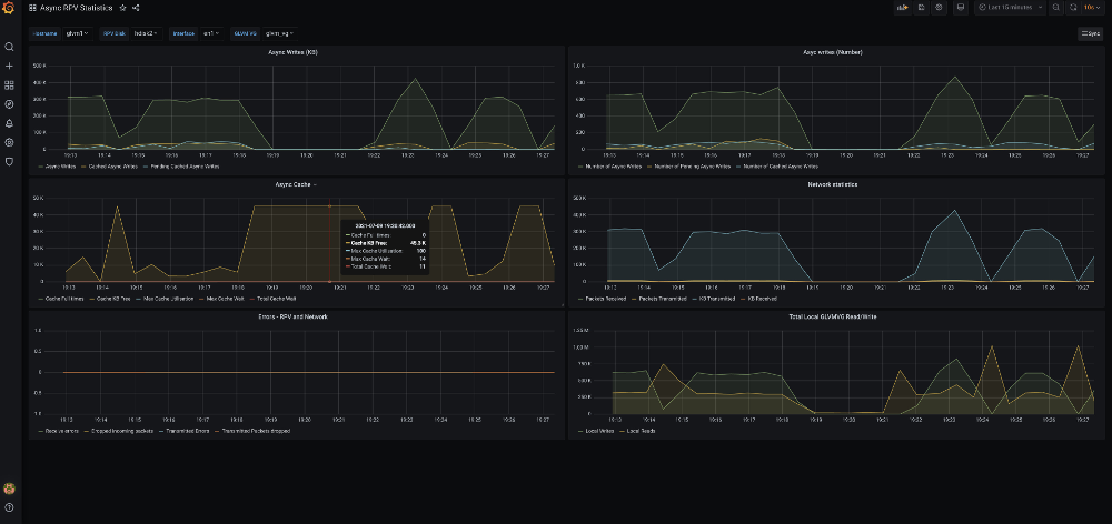
Figure 1-15 Grafana panels for an asynchronous configuration
1.3.1 Tuning the environment
It is recommended to configure the LVM asynchronous cache I/O physical buffer pool and the volume group physical buffer pool to improve performance and avoid I/O hangs. Each logical volume write can be divided into multiple remote physical I/Os. These I/Os are based on the application I/O size and the LVM LTG size because each remote physical write must perform the cache-logical volume write. Therefore, you must tune the aio_cache_pbuf_count slightly more than expected maximum total parallel remote writes. Use the lvmo command to tune this variable, as shown in Example 1-11.
Example 1-11 Display aio buffer pools
lvmo -v gmvg1 -L aio_cache_pbuf_count
NAME CUR DEF BOOT MIN MAX UNIT TYPE
DEPENDENCIES
--------------------------------------------------------------------------------
aio_cache_pbuf_count 0 0 n/a 0 16384 D
max_vg_pbufs
max_vg_pbuf_count
--------------------------------------------------------------------------------
n/a means parameter not supported by the current platform or kernel
If the application uses a JFS2 file system in a cached I/O mode, the file VMM cache can use up most of the memory (90% by default). Also, write behind can be disabled to improve the performance, which causes the caching of pages. Check that the system has enough memory to handle system wide operations other than file VMM cache. It is better to have 4 - 6 GB memory outside the file VMM cache. You can use different methods to reduce the memory footprint that is used by file VMM cache.
If the application is not using the file cache for multiple updates, you can mount the JFS2 file system with the release behind option enabled, which releases pages after read or write:
•mount -o rbr,rbw /fs
•mount -o remount,rbrw /fs
To restrict file cache by using the VMM tunable, tune the maxclient% to the suitable value. For example:
lvmo -aF | grep client
maxclient% = 75
strict_maxclient = 1
|
Note: This option is restricted and must be used after consulting with the IBM Service and development team.
|
1.3.2 Tuning GLVM by using the rpvutil command
The rpvutil command was introduced in AIX 7.2.5 and is used to configure a mirror pool in the RPV client. Table 1-4 lists each attribute and flag that are used with the rpvutil command along with a tunable.
Table 1-4 rpvutil flags
|
Flags and attributes
|
Description
| |
|
-h
|
Displays help information for the rpvutil command.
| |
|
-a
|
Displays the current values of all tunable parameters of the GLVM RPV client.
| |
|
-d tunable
|
Resets the specified tunable parameter to its default value.
| |
|
-h tunable
|
Displays information about specific tunable parameter.
| |
|
-o tunable
|
Displays the value of specified tunable.
| |
|
-v vgname
|
Displays the volume group name for volume group specific tunables.
| |
|
-o tunable [=value]
|
Sets the value of the specified tunable.
| |
If the user does not specify any value for the tunable parameter, the -o tunable_name flag displays the values of the specified tunable parameter. You can specify the following parameters for the rpvutil -o command to tune the operation of GLVM:
•rpv_net_monitor=1|0
Setting rpv_net_monitor to 1 enables monitoring the RPV network so that the RPV client detects any network failures and attempts to resume operation after the network recovers. The default is 0 (disabled).
•compression=1|0
Compresses I/O data packets before they are sent from the client to the server by using the cryptography and compression unit (NX842). The default is 0 (disabled).
•io_grp_latency=1-32768
Used to set the maximum expected delay in milliseconds before receiving the I/O acknowledgment for a mirror pool that is configured in asynchronous mode. The default delay value is 10 ms. A lower value can be set to improve I/O performance, but at the cost of higher CPU consumption.
•nw_sessions=1-99
The number of sessions in a new tunable (available in AIX 7.2.5.2) that controls the number of RPV sessions (sender and receiver threads) to be configured per network.
•cf_tmr_feature=1|0
This setting enables or disables the cache full timer feature and was introduced in AIX 7.3. The default is 0 (disabled).
•cf_tmr_value=2-30
This setting sets the timeout value in seconds for the cache full timer feature. The default value is 10 seconds.
Monitoring GLVM network health
When you set the rpv_net_monitor tunable parameter to 1, GLVM monitors the RPV data network. The RPV client detects network interface states based in the network driver tracked states and attempts to resume the network after interface recovery.
Similarly, when interfaces go down, the RPV client identifies and stops data mirroring. However, if the network interface state is up but remote servers are not reachable over the network, the RPV client io_timeout is used. By default, GLVM monitoring of the network is disabled (set to 0).
Example 1-12 Checking the usage for rpv_net_monitor
# rpvutil -h rpv_net_monitor
Allows RPV client to perform network failure detection and attempt to resume after
recovery. A value of 1 means enabled. A value of 0 means disabled.
Example 1-13 Checking the default value of rpv_net_monitor tunable
# rpvutil -o rpv_net_monitor
rpv_net_monitor = 0
|
Note: The RPV devices must be in a defined state to modify the rpv_net_monitor setting. This tunable is included with AIX 7.2.5 or later.
|
Then, use the chdev command to change the timeout for the RPV client (see Example 1-14, which shows how to change the network timeout of the RPV client’s hdisk3).
Example 1-14 change rpv client timeout
# chdev -l hdisk3 -a io_timeout=180
hdisk3 changed
By default, the io_timeout of the rpvclient is set to 180 seconds.
|
Note: The RPV device must be in a defined state to modify the io_timeout.
|
Hardware-assisted data compression and decompression
IBM introduced special acceleration units for cryptography and compression (NX842) in IBM POWER7+, IBM POWER8®, IBM POWER9™, and IBM Power10™ processors. By default, these accelerators are used to compress main memory for Active Memory Expansion (AME) that is based on the 842 algorithm. For IBM Power Systems hardware before POWER7+, the AIX kernel contains a software implementation of the algorithm to support compression and decompression.
The use of the NX842 accelerator unit requires the installation of the AME license for the server, which involves entering the activation code on the hardware management console (HMC).
To use the compression tunable parameter, ensure that the following prerequisites are met:
•The RPV client and the RPV server are running AIX version 7.2.5, or later with all the latest RPV device drivers.
•The RPV server and the RPV client are IBM Power Systems servers with NX842 acceleration units. If either of the client or server do not have the accelerator unit, there will be a performance impact.
•The AME activation code for the server has been entered.
•The compression tunable parameter is enabled on both servers (RPV server RPV server and RPV client) such that the I/O data packets are compressed in both directions.
When the compression tunable parameter is set to 1, the I/O data packet is compressed by the NX842 acceleration unit before it is sent from the RPV client to the RPV server. If the I/O data packet is compressed successfully, a flag in the packet is set. If an I/O data packet is received by the RPV server with the compression flag set, the RPV server decompresses the I/O data packet. If the NX842 acceleration unit is not available the RPV server attempts software decompression.
It is important to remember that GLVM is a DR solution. Recovering from a disaster requires a large amount of data to be copied over the network, which takes time and places load in the network. Anything to reduce the time and load can be critical to a speedy recovery.
Use of the compression engine
Testing in the lab demonstrated a better I/O performance with compression enabled and it only introduced a short delay in the order of 50 ms. For example, it was observed that without compression, 100 GB took 72 minutes; with compression 65 minutes. More information are provided in this section.
|
Note: Contact IBM for access regarding compression engine.
|
After the activation code is entered, kdb → ipl -cop can be used to confirm that access to the accelerator was granted, as shown in Example 1-15.
Example 1-15 kdb output showing compression engine status
# kdb
WARNING: Version mismatch between unix file and command
kdb
START
END <name>
0000000000001000 00000000076D0000 start+000FD8
F00000002FF47600 F00000002FFE1000 __ublock+000000
000000002FF22FF4 000000002FF22FF8 environ+000000
000000002FF22FF8 000000002FF22FFC errno+000000
F1001104C0000000 F1001104D0000000 pvproc+000000
F1001104D0000000 F1001104D8000000 pvthread+000000
read vscsi_scsi_ptrs OK, ptr = 0xF100091590128E90
(0)> ipl -cop
resource id........00000000
max_sg_len.........00000FF0
comp_ms............00000001
Max sync comp xfer sz....00010000 Max sync comp sg len.....000001FE
decmp_ms...........00000001
Max sync decmp xfer sz....00010000 Max sync decmp sg len.....000001FE
Example 1-16 shows the kdb output if access was not granted.
Example 1-16 kdb output showing access not granted
# kdb
START END <name>
0000000000001000 0000000007140000 start+000FD8
F00000002FF47600 F00000002FFE1000 __ublock+000000
000000002FF22FF4 000000002FF22FF8 environ+000000
000000002FF22FF8 000000002FF22FFC errno+000000
F1001104C0000000 F1001104D0000000 pvproc+000000
F1001104D0000000 F1001104D8000000 pvthread+000000
read vscsi_scsi_ptrs OK, ptr = 0xF100091590128E90
(0)> ipl -cop
Co-processor properties are not found.
The status of the accelerator unit also can be displayed by using the prtconf command, as shown in Example 1-17.
Example 1-17 prtconf showing compression engine enabled
# prtconf
System Model: IBM,8286-42A
Machine Serial Number: 066EE82
Processor Type: PowerPC_POWER8
Processor Implementation Mode: POWER 8
Processor Version: PV_8_Compat
Number Of Processors: 1
Processor Clock Speed: 3525 MHz
CPU Type: 64-bit
Kernel Type: 64-bit
LPAR Info: 107 rt09007
Memory Size: 5120 MB
Good Memory Size: 5120 MB
Platform Firmware level: SV860_177
Firmware Version: IBM,FW860.60 (SV860_177)
Console Login: enable
Auto Restart: true
Full Core: true
NX Crypto Acceleration: Capable and Enabled **********
In-Core Crypto Acceleration: Capable, but not Enabled
Example 1-18 shows the use of the compression tunable.
Example 1-18 rpvutil compression usage
# rpvutil -h compression
Specifies whether the data transferred between the RPV client and server has to be
compressed. A value of 1 means enabled. A value of 0 means disabled.
Example 1-19 shows how to check the value of the compression tunable.
Example 1-19 Listing compression tunable setting (showing disabled)
# rpvutil -o compression
compression = 0
Example 1-20 shows setting the value of the compression tunable.
Example 1-20 Use of rpvutil to set compression tunable to enabled
# rpvutil -o compression=1
Setting compression to 1
Improving IOPS with io_grp_latency
Tunable io_grp_latency in AIX 7.2.5 indicates the maximum expected delay (in milliseconds) before receiving the I/O acknowledgment for a mirror pool that is configured in asynchronous mode.
By default, GLVM forms asynchronous groups once every 10 ms and then performs a write to the remote site; therefore, each write waits for at least 10 ms. Tuning io_grp_latency provides the ability to control group formation time. Reducing this time results in a quicker response back to applications at the cost of possible higher CPU consumption.
Testing in the lab with the default io_grp_latency of 10 ms produced 45 KIOPS, although reducing the default io_grp_latency to 3 ms resulted in 73 KIOPS, which is an increase of 62%.
Example 1-21 shows the usage of the io_grp_latency tunable.
Example 1-21 Showing the io_grp_latency tunable
# rpvutil -h io_grp_latency
Specifies the maximum expected delay, in milliseconds, before receiving the I/O acknowledgement for a mirror pool configured in asynchronous mode. The default value is 10ms.
Example 1-22 shows the current value for the io_grp_latency tunable.
Example 1-22 Displaying current value for the io_grp_latency tunable
# rpvutil -o io_grp_latency -v agmvg
io_grp_latency = 10
Figure 1-16 shows the graph plotted between the KIOPS and block size for two io_grp_latency settings. The yellow line shows the default of 10 ms; blue line shows the setting of 3 ms. A clear improvement of application performance is shown when the io_grp_latency value is reduced.

Figure 1-16 Async IOPS showing improvement due to group timeout
GLVM Parallel RPV sessions
This new tunable was introduced in AIX 7.2.5.2 and can be used to increase the number of parallel RPV sessions (sender and receiver threads) per GLVM network, which results in sending more data in parallel.
A single RPV session consists of a sender thread for transferring data and a receiver thread to receive acknowledgment. Sending more data in parallel improves the data transfer rate and fully uses the network bandwidth.
The nw_sessions setting can range 1 - 99. Example 1-23 shows the use for the number of parallel sessions.
Example 1-23 Usage of rpvutils to set number of sessions
# rpvutil -o nw_sessions=<number of sessions>
Note: number of sessions can be from 1 to 99.
Figure 1-17 shows the number of RPV sessions for varying I/O rates with compression enabled and disabled. Figure 1-17 clearly shows that increasing the number of RPV sessions results in faster data transfer and greater bandwidth usage.
Figure 1-17 Graph demonstrating the effect of increasing the number of rpv sessions
Cache full timer
If the cache full timer (cf_tmr_feature) is enabled, the rpvutil command starts a timer when the I/O buffer cache is full. When the I/O buffer cache is full, all the subsequent I/O requests are buffered internally.
When the timer expires, all the I/O requests that are buffered internally are invalidated and the threads of the application are released from the queue of threads that are waiting for the response from the I/O operations. Also, the physical volumes are moved to the stale state. You can set the timer value by using the cf_tmr_value tunable parameter.
The timer value (cf_tmr_value) sets the timeout value for the cache full timer feature. The timeout value can range 2 - 30 seconds. The default value is 10 seconds.
1.4 Performance analysis
This section analyzes performance by using a range of tuning values. It also shows how performance can be improved if the tunables are correctly adjusted.
1.4.1 AIX disk subsystem and network tunables
Asynchronous GLVM performance can achieve performance that is near that of local LVM Mirroring if a larger block size of 256K and concurrent I/O are used, and is correctly tuned.
Table 1-5 lists tunable ranges, the default values, and the value that is discovered to give better performance.
Table 1-5 Tunable ranges and recommended values
|
Area (group into category)
|
Tunable
|
Range
|
Default value
|
Values used in testing
|
Comments
|
|
GLVM
|
io_grp_latency
|
2 - 10 ms
|
10 ms
|
3 ms
|
|
|
LVM
|
LTG size
|
|
|
512KB (when compression enabled).
|
|
|
MWCC
|
Active/Passive/disable
|
Active
|
Passive
|
| |
|
aio_cache_buf_count
|
512 - 16384
|
|
16384
|
| |
|
AIX disk subsystem
|
queue_depth
|
8 - 256
|
40
|
256
|
Value is selected based on storage
recommendation
|
|
max_transfer
|
up to 16 MB
|
0x80000
|
512 KB (when compression is enabled).
|
| |
|
AIX networking
|
tcp_sendspace
|
|
128 KB
|
50 MB
|
|
|
tcp_recvspace
|
|
64 KB
|
50 MB
|
| |
|
sack
|
0/1
|
0
|
1
|
| |
|
tcp_nodelayack
|
0/1
|
|
1
|
| |
|
rfc1323
|
0/1
|
1
|
1
|
|
1.4.2 AIX GLVM RPV tunables
This section describes the graphs that are created by the various tunable parameters (delay between the sites, number of parallel RPV network sessions, and so on). These graphs help customers decide the value for each tunable based on their I/O workload and the delay and distance between their sites.
|
Note: Because of the results were recorded in a laboratory environment, these results depend on various factors, such as workload profile, resource use, environment configuration, and network bandwidth.
|
Background information
Consider the following points about resetting counters in preparation to capture the data for the graphs:
•To reset the counter, use the command rpvstat -r.
•To identify the time that is considered to complete remote data transfer, reset counters and look for the Total completed AIO data value, which is the KB that is completed at remote site. After the I/O completes at the remote site, look for the AIO total complete time value.
To prepare the graphs, the asynchronous I/O transfer rate was determined by using the rpvstat -A and rpvstat -G commands. These commands provide the details of the data that was transferred and completed on the remote site, and the I/Os yet to complete on the remote site.
Asynchronous transfer rate is shown in Example 1-24.
Example 1-24 rpvstat -A output showing no pending remote writes and the completed data
# rpvstat -A
Remote Physical Volume Statistics:
Completd Completed Cached Cached Pending Pending
Async Async Async Async Async Async
RPV Client ax Writes KB Writes Writes KB Writes Writes KB Writes
------------ -- -------- ----------- -------- ----------- -------- -----------
hdisk12 A 9814 4324100 1784555 105233820 0 0
Use the rpvstat -G command to find the AIO total complete time, as shown in Example 1-25.
Example 1-25 rpvstat -G output
# rpvstat -G
Remote Physical Volume Statistics:
GMVG name .................................... agmvg
AIO total commit time (ms) ................... 0
Number of committed groups ................... 0
Total committed AIO data (KB) ................ 0
Average group commit time (ms) ............... 1
AIO data committed per sec (KB) .............. 1000
AIO total complete time (ms) ................. 12978
Number of completed groups ................... 1
Total completed AIO data (KB) ................ 3584
Average group complete time (ms) ............. 12978
AIO data completed per sec (KB) .............. 0
Number of groups read ........................ 0
Total AIO data read (KB) ..................... 0
Total AIO cache read time (ms) ............... 16
Average group read time (ms) ................. 63
AIO data read per sec (KB) ................... 0
Number of groups formed ...................... 0
Total group formation time (ms) .............. 0
Average group formation time (ms) ............ 1
Number of cache fulls detected ............... 0
Total cache usage time (ms) .................. 5940
Total wait time for cache availability (ms) .. 0
Total AIO write data in transit (KB) ......... 15744
Lab environment configuration
A distance simulator is used between the two sites so that the delay can be varied for each test. The environment consists of a volume group with single local disk and a single RPV, each 500 GB. A 200 GB logical volume is created in the volume group and a JFS2 file system is created.
Flexible I/O tester (FIO) is used to generated a 100 GB file to simulate I/O workload in the file system, with the I/O performance analyzed for the different simulated distances. The FIO parameters for generating the file I/O workload are shown in Example 1-26.
Example 1-26 FIO configuration settings
[global]
randrepeat=0
buffered=1
direct=0
norandommap=1
group_reporting=1
size=100g
io_size=100g
ioengine=posixio
rw=randrw
bs=1024k
iodepth=64
rwmixread=0
rwmixwrite=100
time_based=0
numjobs=1
fallocate=1
[job1]
filename=/agfs/XXXX.text
1.4.3 Analyzing I/O rates for different configurations
In this section, we describe the tests that were run in the lab.
Asynchronous I/O data transfer versus inter-site delay
Figure 1-18 shows the time taken for the test data to be transferred (100 GB) for different inter-site delays (in ms) with compression enabled and disabled.
|
Note: Inter-site delays are generated by using a commercial distance simulator in the network that connects the two AIX LPARs.
|
Figure 1-18 Async I/O transfer time with 50 parallel sessions (compression enabled and disabled)
Figure 1-19 shows the I/O data transfer rate in MBps for different inter-site delays with compression enabled and disabled.
Figure 1-19 Async I/O transfer rate with 50 parallel sessions (compression enabled and disabled)
Consider the following points:
•Compression starts to improve performance after the inter-site delay increases higher than 25 ms and continues to improve as the delay increases.
•Asynchronous I/O transfer time increases almost linearly with increasing inter-site delay with compression disabled. However, with compression enabled, the transfer time increases slowly.
Asynchronous I/O transfer rate versus GLVM RPV sessions
The graphs that is shown in Figure 1-20 and Figure 1-21 on page 43 show the asynchronous I/O data transfer rates for a range of RPV network sessions (nw_sessions) with compression enabled and disabled. The graph in Figure 1-20 uses an inter-site delay of 20 ms; the graph in Figure 1-21 on page 43 a delay of 50 ms.

Figure 1-20 Async I/O transfer rate (MBps) versus rpv sessions with Fixed 20ms delay between sites
Consider the following points:
•Figure 1-20 shows that the data transfer rate increases as the number of parallel RPV sessions increases.
•Compression only shows an improvement in performance until reaching 45 RPV sessions with a 20 ms inter-site delay.

Figure 1-21 Async I/O transfer rate (MBps) versus rpv sessions with Fixed 50ms delay between sites
Consider the following points:
•Figure 1-21 shows that the data transfer rate increases as the number of parallel RPV sessions increases.
•Compression always improves the data transfer rate with an inter-site delay of 50 ms.
Asynchronous I/O transfer rate versus I/O data in GB
Figure 1-22 shows the asynchronous I/O data transfer rate in MBps for different I/O data workloads in GB for compression enabled and disabled. The inter-site delay is set to 50 ms and the number of parallel RPV sessions are set to 50.

Figure 1-22 sync I/O transfer rate (MBps) versus I/O Workload data in GB
|
Note: Delay between the sites is fixed to 50 milliseconds and 50 parallel RPV network sessions. The asynchronous I/O transfer rate is measured for different sizes of the data transfer between the sites.
|
Consider the following points:
•Figure 1-22 shows that the data transfer rate is almost constant for different sizes of data and it varies for different I/O workloads.
•Data transfer rate improves with compression enabled.
Compression ratio
In preparing the graphs, the compression ratio was also measured for some of the runs and was found to vary 2:1 - 18:1.
|
Note: The compression ratio was measured by using the data that was generated by the FIO tool. Your results can vary with real-world data.
|
1.5 Initial setup
When planning to use a public cloud as a DR data center (Hybrid Cloud scenario), invariably you might have a considerable data footprint in the on-premises data center. In these cases, it is important to synchronize the remote disks in the public cloud with the local disks before asynchronous GLVM can be configured. Depending on data size and network speed, it can take too long to synchronize the data.
Several methods can be used to complete this setup, as discussed next.
1.5.1 Network-based disk seeding
In this case, the administrator can set up asynchronous GLVM across the sites. After the setup is complete, asynchronous GLVM performs data mirroring to the remote site synchronously first to sync the remote disks.
This method requires a high-speed network connection. It also can affect local application performance during the synchronization time. Mirroring the volume group by default initializes synchronization to the remote site over the network.
1.5.2 Lift and shift method
In this method, a copy of the local disks is made to portable media, which is then transported to the remote site. GLVM is then configured by using the local disks and the copy at the remote site.
Although public cloud environments do not accept disks to be shipped, alternative methods are available to achieve the same result, including the examples that are described next.
Cloud Object Storage
Use Cloud Object Storage (COS) as the intermediate media to transfer disks:
1. Create local copies of disks.
2. Use tools, such as Amazon Web Services (AWS) to push each disk as an object into cloud object storage.
|
Note: COS typically has maximum limit of 10 TB for an object. If your disk is larger, you might have to use a split method to push the disk in pieces.
|
3. Log in to public cloud-based remote VM and pull the objects from COS. Then, write to fresh disks in the public cloud.
4. Follow the steps to setup GLVM as described in Appendix C, “Configuring IBM Geographic Logical Volume Manager” on page 67 and then, synchronize any delta changes.
Mass Data transfer media
Use Mass Data transfer media (for example, MDM devices from IBM Cloud) to transfer disks into the public cloud:
1. Create local copies of disks.
2. Write the disks as files onto the MDM NFS mount point.
3. Ship MDM.
Files are stored as objects in COS by the Cloud provider.
4. Log in to public Cloud based remote VM, pull the objects from COS, and then, write to fresh disks in the public cloud.
5. Follow the steps to set up GLVM as described in Appendix C, “Configuring IBM Geographic Logical Volume Manager” on page 67 and synchronize any delta changes.
Whichever method is chosen, some initial steps must be performed to create copies of the disks locally.
The following sample process creates copies of disks to ship to public cloud by using a single volume group with a couple of disks:
1. Setup for local LVM mirroring with the same size as previous copies.
2. Synchronize the local copies by using the mirrorvg command.
3. After the synchronization is complete, split the VG by using the splitvg command and separate the second copy.
4. Ship the second copy of the disks to the remote site by using one of the following methods:
– Physically transport the disks.
– Copy the disks contents to an NFS device called Mass Data Migration (MDM) and ship it to the IBM cloud. IBM places those files in COD. From the server, connect to the COS and restore the data from those files to locally defined disks.
5. Setup GLVM (see Appendix C, “Configuring IBM Geographic Logical Volume Manager” on page 67) and configure the local and remote servers.
6. Create RPV servers by using the disks that were transported to the remote server and RPV clients pointing to them.
7. Run the joinvg command to add the RPV clients back into the local volume group.
8. Run the sync command to synchronize the stale partitions.
After initial seeding (synchronization) is completed, the volume group can be converted into asynchronous mode by using the chmp command.
1.5.3 Example GLVM setup: Two sites and one PV at each site
After planning the network configuration and bandwidth, configuring GLVM is relatively simple.
For a stand-alone configuration, the sites must be configured and then the servers and clients configured. PowerHA SystemMirror handles the sites and includes an option for multiple networks. The GUI includes a GLVM configuration wizard.
The GMVG is configured on one site by using the RPV clients. The only difference for asynchronous mode is that mirror pools are compulsory and a local aio_cache logical volume must be included in each pool.
Table 1-6 lists the steps of a simple GLVM configuration that features two nodes and one disk on each node that are used to create the GMVG. Initially, GLVM is configured to be synchronous; then, it is changed to be asynchronous.
Table 1-6 Settings used in the scenarios
|
Setting
|
Site 1
|
Site 2
|
|
Site name
|
glvm1
|
glvm2
|
|
Address
|
192.168.200.138
|
192.168.200.78
|
|
Mirror pool
|
glvm1
|
glvm2
|
|
PVIDs
|
00c8d23057b60c26
|
00c8cf4057f2d781
|
|
Volume group
|
glvm_vg
| |
|
jfs2 log logical volume
|
glvmlv01
| |
|
jfs2 logical volume
|
glvmlv02
| |
|
aio cache
|
glvm2_cache
|
glvm1_cache
|
|
file system
|
/glvm_data
| |
1.5.4 Setup guidance
This section describes setting up the necessary sites.
Configuring sites
Complete the following steps to configure the sites:
1. Configure the sites by using the command line:
/usr/sbin/rpvsitename -a [sitename]
SMIT also can be used (see Example 1-27):
smitty glvm_utils → Remote Physical Volume Servers.
→ Remote Physical Volume Server Site Name Configuration.
→ Define / Change / Show Remote Physical Volume Server Site Name.
→ Remote Physical Volume Server Site Name Configuration.
→ Define / Change / Show Remote Physical Volume Server Site Name.
Example 1-27 Setting site name with SMIT
Define / Change / Show Remote Physical Volume Server Site Name
Type or select values in entry fields.
Press Enter AFTER making all desired changes.
[Entry Fields]
* Remote Physical Volume Server Site Name [glvm2]
F1=Help F2=Refresh F3=Cancel F4=List
F5=Reset F6=Command F7=Edit F8=Image
F9=Shell F10=Exit Enter=Do
2. Enter the site name.
3. Repeat these steps on the node on the other site.
Creating the RPV server on glvm2
Complete the following steps to create the RPV server on glvm2:
1. Use the command line, as shown in Example 1-28.
Example 1-28 Creating the RPV server
/usr/sbin/mkdev -c rpvserver -s rpvserver -t rpvstype -a
rpvs_pvid=00c8cf4057f2d781 -a client_addr='192.168.200.138' -a auto_online='n'
rpvserver0 Available
SMIT also can be used (see Example 1-29):
smit glvm_utils → Remote Physical Volume Servers.
→ Add Remote Physical Volume Servers.
→ Add Remote Physical Volume Servers.
Example 1-29 Creating the RPV server with SMIT
Add Remote Physical Volume Servers
Type or select values in entry fields.
Press Enter AFTER making all desired changes.
[Entry Fields]
Physical Volume Identifiers 00c8cf4057f2d781
* Remote Physical Volume Client Internet Address [192.168.200.138] +
Configure Automatically at System Restart? [no] +
Start New Devices Immediately? [yes] +
F1=Help F2=Refresh F3=Cancel F4=List
F5=Reset F6=Command F7=Edit F8=Image
F9=Shell F10=Exit Enter=Do
2. Select the local physical volume from the name and pvid that are listed.
3. Set the following values:
– Configure Automatically at System Restart: No
– Start New Devices Immediately: Yes
Creating the RPV client on glvm1
Complete the following steps to create the RPV client on glvm1:
1. Use the command line, as shown in Example 1-30.
Example 1-30 Creating the RPV client
/usr/sbin/mkdev -c disk -s remote_disk -t rpvclient -a pvid=00c8cf4057f2d781
-a server_addr='192.168.200.78' -a local_addr='192.168.200.138'
-a io_timeout='180'
hdisk2 Available
SMIT also can be used (see Example 1-31):
smit glvm_utils → Remote Physical Volume Clients.
Example 1-31 Adding the RPV client with SMIT
Add Remote Physical Volume Clients
Type or select values in entry fields.
Press Enter AFTER making all desired changes.
[Entry Fields]
Remote Physical Volume Server Internet Address 192.168.200.78
Remote Physical Volume Local Internet Address 192.168.200.138
Physical Volume Identifiers 00c8cf4057f2d78100000>
I/O Timeout Interval (Seconds) [10] #
Start New Devices Immediately? [yes] +
F1=Help F2=Refresh F3=Cancel F4=List
F5=Reset F6=Command F7=Edit F8=Image
F9=Shell F10=Exit Enter=Do 
2. Select IPv6, if required.
3. Enter the RPV server IP address.
4. Select:
– The local network address
– The hdisk on the server to which this client points
– I/O timeout Interval (10)
– Start New Devices Immediately (yes)
Creating the GMVG
Before configuring GLVM for the reverse I/O flow, the physical volumes must be configured and then, the GMVG created.
Complete the following steps:
1. Create a scalable volume group by using hdsik1 and hdisk2 and setting Superstrict by using the command line, as shown in Example 1-32.
Example 1-32 Create the scalable volume group
mkvg -f -S -M s -n -y glvm_vg hdisk1 hdisk2
SMIT also can be used (see Example 1-33):
smitty _mksvg
Example 1-33 Create Volume Group with local disk and RPV client
Add a Scalable Volume Group
Type or select values in entry fields.
Press Enter AFTER making all desired changes.
[Entry Fields]
VOLUME GROUP name [glvm_vg]
Physical partition SIZE in megabytes +
* PHYSICAL VOLUME names [hdisk1 hdisk2] +
Force the creation of a volume group? no +
Activate volume group AUTOMATICALLY no +
at system restart?
Volume Group MAJOR NUMBER [] +#
Create VG Concurrent Capable? no +
Max PPs per VG in units of 1024 32 +
Max Logical Volumes 256 +
Enable Strict Mirror Pools Superstrict +
Infinite Retry Option no +
F1=Help F2=Refresh F3=Cancel F4=List
F5=Reset F6=Command F7=Edit F8=Image
F9=Shell F10=Exit Enter=Do
2. Turn off bad block relocation for the volume group, as shown in Example 1-34.
Example 1-34 Turn off bad block relocation
chvg -b n glvm_vg
3. Add disks to mirror pools at each site, as shown in Example 1-35.
Example 1-35 Add disks to mirror pools
chpv -p glvm1 hdisk1
chpv -p glvm2 hdisk2
4. Display the pool details for the disks, as shown in Example 1-36.
Example 1-36 Display mirror pool details
lspv hdisk1
PHYSICAL VOLUME: hdisk1 VOLUME GROUP: glvm_vg
PV IDENTIFIER: 00c8d23057b60c26 VG IDENTIFIER 00c8d23000004b000000017a5c413a99
PV STATE: active
STALE PARTITIONS: 0 ALLOCATABLE: yes
PP SIZE: 16 megabyte(s) LOGICAL VOLUMES: 0
TOTAL PPs: 1275 (20400 megabytes) VG DESCRIPTORS: 2
FREE PPs: 1275 (20400 megabytes) HOT SPARE: no
USED PPs: 0 (0 megabytes) MAX REQUEST: 512 kilobytes
FREE DISTRIBUTION: 255..255..255..255..255
USED DISTRIBUTION: 00..00..00..00..00
MIRROR POOL: glvm1
SMIT: also can be used (see Example 1-37):
smit chpv → Enter physical volume name.
Example 1-37 Setting the mirror pool with SMIT
Change Characteristics of a Physical Volume
Type or select values in entry fields.
Press Enter AFTER making all desired changes.
[Entry Fields]
* Physical volume NAME hdisk1
Allow physical partition ALLOCATION? yes +
Physical volume STATE active +
Set hotspare characteristics n +
Set Mirror Pool [glvm1] +
Change Mirror Pool Name []
Remove From Mirror Pool +
F1=Help F2=Refresh F3=Cancel F4=List
F5=Reset F6=Command F7=Edit F8=Image
F9=Shell F10=Exit Enter=Do
The resulting configuration is shown in Example 1-38.
Example 1-38 Displaying the mirror pool configuration
lsmp -A glvm_vg
VOLUME GROUP: glvm_vg Mirror Pool Super Strict: yes
MIRROR POOL: glvm1 Mirroring Mode: SYNC
MIRROR POOL: glvm2 Mirroring Mode: SYNC
Creating logical volumes for synchronous replication
The logical volumes are now created by using both disks, superstrict, passive MWC, and defining the mirror pool for each copy. Complete the following steps:
1. Use the command line as shown in Example 1-39.
Example 1-39 Create logical volumes for synchronous replication
mklv -c 2 -t jfs2log -y glvmlv01 -p copy1=glvm1 -p copy2=glvm2 -b n -w p -s s glvmvg 1
mklv -c 2 -t jfs2 -y glvmlv02 -p copy1=glvm1 -p copy2=glvm2 -b n -w p -s s glvmvg 100
SMIT also can be used:
smitty mklv → Enter the volume group name
If a jfs2log logical volume is used rather than inline logs, see Example 1-40.
Example 1-40 Create the logical volume
Add a Logical Volume
Type or select values in entry fields.
Press Enter AFTER making all desired changes.
[TOP] [Entry Fields]
Logical volume NAME [glvmlv01]
* VOLUME GROUP name glvm_vg
* Number of LOGICAL PARTITIONS [1] #
PHYSICAL VOLUME names [hdisk1 hdisk2] +
Logical volume TYPE [jfs2log] +
POSITION on physical volume middle +
RANGE of physical volumes minimum +
MAXIMUM NUMBER of PHYSICAL VOLUMES [] #
to use for allocation
Number of COPIES of each logical 2 +
partition
Mirror Write Consistency? passive +
Allocate each logical partition copy superstrict +
on a SEPARATE physical volume?
RELOCATE the logical volume during yes +
reorganization?
Logical volume LABEL [glvmlv01]
MAXIMUM NUMBER of LOGICAL PARTITIONS [512] #
Enable BAD BLOCK relocation? no +
SCHEDULING POLICY for writing/reading parallel +
logical partition copies
Enable WRITE VERIFY? no +
File containing ALLOCATION MAP []
Stripe Size? [Not Striped] +
Serialize IO? no +
Mirror Pool for First Copy glvm1 +
Mirror Pool for Second Copy glvm2 +
Mirror Pool for Third Copy +
Infinite Retry Option no +
F1=Help F2=Refresh F3=Cancel F4=List
F5=Reset F6=Command F7=Edit F8=Image
F9=Shell F10=Exit Enter=Do
2. Create a logical volume for the JFS2 file system data; then, create the file system by using the data and logical volumes.
Creating logical volumes for asynchronous replication
When configuring asynchronous GLVM, complete the following steps to create the aio_cache logical volume for each site:
1. Use the command line as shown in Example 1-41.
Example 1-41 Create the aio_cache logical volume for each site
mklv -c 1 -t aio_cache -y glvmlv1_cache -p copy1=glvm1 -b n -w p glvmvg 4
mklv -c 1 -t aio_cache -y glvmlv2_cache -p copy1=glvm2 -b n -w p glvmvg 4
2. Create the cache for site B in pool glvm1 and then the cache for site A in pool glvm2.
Or, create the cache for Site B in the glvm1 mirror pool by using SMIT (see Example 1-42):
smitty mklv → Enter the volume group name.
Example 1-42 Create the aio_cache logical volume for each site with SMIT
Add a Logical Volume
Type or select values in entry fields.
Press Enter AFTER making all desired changes.
[TOP] [Entry Fields]
Logical volume NAME [glvm1_cache]
* VOLUME GROUP name glvm_vg
* Number of LOGICAL PARTITIONS [4] #
PHYSICAL VOLUME names [hdisk1] +
Logical volume TYPE [aio_cache] +
POSITION on physical volume middle +
RANGE of physical volumes minimum +
MAXIMUM NUMBER of PHYSICAL VOLUMES [] #
to use for allocation
Number of COPIES of each logical 2 +
partition
Mirror Write Consistency? passive +
Allocate each logical partition copy yes +
on a SEPARATE physical volume?
RELOCATE the logical volume during yes +
reorganization?
Logical volume LABEL [glvm1_cache]
MAXIMUM NUMBER of LOGICAL PARTITIONS [512] #
Enable BAD BLOCK relocation? no +
SCHEDULING POLICY for writing/reading parallel +
logical partition copies
Enable WRITE VERIFY? no +
File containing ALLOCATION MAP []
Stripe Size? [Not Striped] +
Serialize IO? no +
Mirror Pool for First Copy glvm1 +
Mirror Pool for Second Copy +
Mirror Pool for Third Copy +
Infinite Retry Option no +
F1=Help F2=Refresh F3=Cancel F4=List
F5=Reset F6=Command F7=Edit F8=Image
F9=Shell F10=Exit Enter=Do
3. Create site A’s aio_cache logical volume in mirror pool glvm2, which consists of the physical volumes on site B.
The resulting configuration is displayed by using the lsvg command, as shown in Example 1-43.
Example 1-43 GMVG (glvm_vg) logical volumes
# lsvg -m glvm_vg
Logical Volume Copy 1 Copy 2 Copy 3
glvmlv01 glvm1 glvm2 None
glvmlv02 glvm1 glvm2 None
glvm2_cache glvm1 None None
glvm1_cache glvm2 None None
Now that the GMVG is configured with the RPV server and client pairs are configured for replication from site A to site B, the RPV server and client pairs must be configured for the reverse flow.
First, the RPV clients and then the RPV servers must be halted, as described next
Starting and stopping GLVM services
Complete the following steps:
1. Stop the rpvclient, run the following command:
rmdev -l hdisk2
2. To stop the rpvserver, run the following command:
rmdev -l rpvserver0
3. Configure the RPV server on glvm1 (site A) and the corresponding RPV client on glvm2 (site B). After they are available, the GMVG (glvm_vg) can be imported to glvm2.
After the volume group is available and active on one site, the file systems then can be mounted. A GMVG was now successfully completed, which mirrors data between site A and site B.
Verification of RPV client with respect to GLVM
After initial setup, ensure that the PV state is active and the network connectivity is correct.
Check the GLVM configuration in the command line (see Example 1-44).
Example 1-44 Running verification of GLVM configuration
# lsglvm -c
Checking Volume Group glvm_vg
# Site Copy Physical Volumes
#glvm1 PV1 hdisk1
glvm2 PV2 hdisk2
Checking Logical Volume glvmlv01
Checking Logical Volume glvmlv02
Checking Logical Volume glvm2_cache
Checking Logical Volume glvm1_cache
SMIT also can be used (see Example 1-45):
smit glvm_utils
→ Geographically Mirrored Volume Groups.
→ Verify Mirror Copy Site Locations for a Volume Group.
→ Choose the Volume Group.
→ Geographically Mirrored Volume Groups.
→ Verify Mirror Copy Site Locations for a Volume Group.
→ Choose the Volume Group.
Example 1-45 GLVM verification with SMIT
Before command completion, additional instructions may appear below.
Checking Volume Group glvm_vg
# Site Copy Physical Volumes
#glvm1 PV1 hdisk1
glvm2 PV2 hdisk2
Checking Logical Volume glvmlv01
Checking Logical Volume glvmlv02
Checking Logical Volume glvm1_cache
Checking Logical Volume glvm2_cache
F1=Help F2=Refresh F3=Cancel F6=Command
F8=Image F9=Shell F10=Exit /=Find
n=Find Next
1.5.5 Changing GLVM mirroring modes
GLVM mirroring modes can be easily changed if the requirements for asynchronous configuration are met.
Changing synchronous to asynchronous
Assuming that the aio_cache was created for each mirror pool, all that is required is to change the property of the mirror pool to asynchronous.
Asynchronous mirror pools feature one extra property: the High Water Mark. This variable sets the percentage of the cache that can be used before new write requests must wait for mirroring to catch up.
To change the mirror pool, complete the following steps:
1. Run the following commands:
chmp -A -m glvm1 -c glvm1_cache -h 75 glvm_vg
chmp -A -m glvm2 -c glvm2_cache -h 75 glvm_vg
SMIT also can be used:
smit glvm_utils
→ Geographically Mirrored Volume Groups.
→ Manage Geographically Mirrored Volume Groups with Mirror Pools.
→ Configure Mirroring Properties of a Mirror Pool.
→ Convert to Asynchronous Mirroring for a Mirror Pool.
→ Geographically Mirrored Volume Groups.
→ Manage Geographically Mirrored Volume Groups with Mirror Pools.
→ Configure Mirroring Properties of a Mirror Pool.
→ Convert to Asynchronous Mirroring for a Mirror Pool.
2. Select the following settings:
– Mirror pool
– LV cache
3. Set the high water mark for the cache (%).
4. Repeat these steps for the other mirror pool.
Listing the status of the volume group now shows it as ASYNC, as shown in Example 1-46.
Example 1-46 Display the asynchronous configuration
# lsmp -AL glvm_vg
VOLUME GROUP: glvm_vg Mirror Pool Super Strict: yes
MIRROR POOL: glvm1 Mirroring Mode: ASYNC
ASYNC MIRROR STATE: inactive ASYNC CACHE LV: glvm1_cache
ASYNC CACHE VALID: yes ASYNC CACHE EMPTY: yes
ASYNC CACHE HWM: 75 ASYNC DATA DIVERGED: no
MIRROR POOL: glvm2 Mirroring Mode: ASYNC
ASYNC MIRROR STATE: active ASYNC CACHE LV: glvm2_cache
ASYNC CACHE VALID: yes ASYNC CACHE EMPTY: no
ASYNC CACHE HWM: 75 ASYNC DATA DIVERGED: no
Changing asynchronous to synchronous
To change GLVM operation to synchronous mode, run the following commands:
chmp -S -m glvm1 glvm_vg
chmp -S -m glvm2 glvm_vg
For more information about the steps to configure GLVM in the lab and the testing, see Appendix C, “Configuring IBM Geographic Logical Volume Manager” on page 67.
1.5.6 Useful lsglvm command options
The following examples show useful lsglvm command options to display GMVG and mirror pool status.
Example 1-47 shows the output from lsglvm with no flags and displays the remote PV details.
Example 1-47 lsglvm output
# lsglvm
#Volume Group Logical Volume RPV PVID Site
glvm_vg glvm1_cache hdisk2 00c8cf4057f2d781 glvm2
glvm_vg glvmlv01 hdisk2 00c8cf4057f2d781 glvm2
glvm_vg glvmlv02 hdisk2 00c8cf4057f2d781 glvm2
Example 1-48 lsglvm showing mirror pool details for remote PV
# lsglvm -p
glvm_vg: (Asynchronously mirrored)
# Logical Volume RPV PVID Site Mirror Pool
glvm1_cache hdisk2 00c8cf4057f2d781 glvm2 glvm2
glvmlv01 hdisk2 00c8cf4057f2d781 glvm2 glvm2
glvmlv02 hdisk2 00c8cf4057f2d781 glvm2 glvm2
Example 1-49 shows lsglvm with site and PV mapping for each LV.
Example 1-49 lsglvm with mapping for each LV
# lsglvm -m
# Table of All Physical Volumes in all Geographic Logical Volumes
# Site Copy Physical Volumes
glvm_vg
glvmlv01
glvm1 PV1 hdisk1
glvm2 PV2 hdisk2
glvmlv02
glvm1 PV1 hdisk1
glvm2 PV2 hdisk2
glvm2_cache
glvm1 PV1 hdisk1
glvm1_cache
glvm2 PV1 hdisk2
Example 1-50 shows the output of running lsglvm verification.
Example 1-50 lsglvm checking the configuration
# lsglvm -c
Checking Volume Group glvm_vg
# Site Copy Physical Volumes
#glvm1 PV1 hdisk1
glvm2 PV2 hdisk2
Checking Logical Volume glvmlv01
Checking Logical Volume glvmlv02
Checking Logical Volume glvm2_cache
Checking Logical Volume glvm1_cache
1.6 Maintenance tasks
The following sections discuss some of the common GLVM maintenance tasks. It is assumed that the RPV servers or RPV clients are active.
1.6.1 Changing sites
The following steps show how to move the active site from one data center to the other. If a failure OCCURS at the active site, the same process is used to start GLVM at the alternative site, with the added challenge of managing the cache and data divergence for the asynchronous mirror. For more information, see 1.6.2, “Data divergence” on page 58.
|
Note: These steps outline what PowerHA SystemMirror follows if GLVM is managed.
|
To change sites (in this example, from Site A to Site B) complete the following steps:
1. On Site A (if accessible):
a. Halt the applications and wait for the cache to drain if asynchronous.
b. Unmount the file systems.
c. Deactivate the GMVGs:
varyoffvg glvm_vg
d. Check activity by using the rpvstat command.
e. Stop the RPV clients:
rmdev -l hdisk2
2. On Site B, stop the RPV servers:
rmdev -l rpvserver0
3. On Site A (if accessible), start the RPV servers:
mkdev -l rpvserver0
4. On Site B:
a. Start the local RPV client:
mkdev -l hdisk2
b. Activate the GMVGs:
varyonvg glvm_vg
c. Set the preferred read to the disks at Site B. For more information, see 1.6.4, “Setting preferred read to local disks for standalone” on page 59.
d. Mount the file systems.
e. Start the applications.
1.6.2 Data divergence
Data divergence occurs when the GMVG is activated on a site while outstanding data exists in the other site’s cache and is only an issue for asynchronous GLVM. In this scenario, the administrator must decide what to do with the updates in the cache that have yet to be applied to the site they are about to bring online.
The following questions must be considered:
•How much data is in the cache?
•Can the cache be recovered?
•Can the data be rebuilt, do manual records exist?
•Can the other site be brought on line, and if so, how long will it take?
Then, the decision can be made to start operations at the surviving site and attempt to rebuild the lost data, or wait for the other site to recover.
Depending on the type of initial failure, if the cache still exists at the original site, a decision must be made when moving back about what to do with the now out-of-date cache.
All these decisions depend on the type of failure and the amount and recoverability of the data involved. Therefore, no single answer or best practice fits every scenario.
1.6.3 Site divergence or split brain
No discussion of a two site solution is complete without mentioning the issue of site divergence or split brain, which is a situation when, because of some issue, both sites activated GLVM and mounted the file systems locally.
PowerHA SystemMirror ensures that this issue does not occur. In the stand-alone configuration, it requires the administrator to incorrectly start GLVM at the second site while it is still active at the first site.
If this issue occurs, data changes occur at each site that are not recorded on the other site. The following options depend on the configuration:
•PowerHA managed
The PowerHA SystemMirror includes options to handle data divergence that include copying data that is not replicated from your chosen site and backing out the changes from the other site.
•Stand-alone
Although you can synchronize the updates that are not replicated from your chosen site to the other site, changes are made to the other site that are not replicated back. This means that the copy at the remote site is now unusable and a full synchronization of all logical volumes must be done.
1.6.4 Setting preferred read to local disks for standalone
PowerHA SystemMirror can set the preferred read to siteaffinity; therefore, all reads use local disks if they are available. To set the preferred read for each logical volume, run the following command:
chlv -R n <LV_Name>
Where: n = copy number for the mirror pool.
For example:
chlv -R 1 glvmlv01
The details of the lslv command output and the changed preferred read are shown in Example 1-51. To turn off this feature, run the following command:
chlv -R 0 glvmlv02
Example 1-51 lslv showing the preferred read mirror pool
# lslv glvmlv01
LOGICAL VOLUME: glvmlv01 VOLUME GROUP: glvm_vg
LV IDENTIFIER: 00c8d23000004b000000017a5c413a99.1 PERMISSION: read/write
VG STATE: active/complete LV STATE: opened/syncd
TYPE: jfs2log WRITE VERIFY: off
MAX LPs: 512 PP SIZE: 16 megabyte(s)
COPIES: 2 SCHED POLICY: parallel
LPs: 1 PPs: 2
STALE PPs: 0 BB POLICY: non-relocatable
INTER-POLICY: minimum RELOCATABLE: yes
INTRA-POLICY: middle UPPER BOUND: 12
MOUNT POINT: N/A LABEL: None
DEVICE UID: 0 DEVICE GID: 0
DEVICE PERMISSIONS: 432
MIRROR WRITE CONSISTENCY: on/PASSIVE
EACH LP COPY ON A SEPARATE PV ?: yes (superstrict)
Serialize IO ?: NO
INFINITE RETRY: no PREFERRED READ: 0
DEVICESUBTYPE: DS_LVZ
COPY 1 MIRROR POOL: glvm1
COPY 2 MIRROR POOL: glvm2
COPY 3 MIRROR POOL: None
ENCRYPTION: no
|
Note: The preferred read must be set when you change the site; otherwise, all reads are done from the remote logical volumes.
|
Changing the preferred read is shown in Example 1-52.
Example 1-52 Changing the preferred read to mirror pool copy 1
#chlv -R 1 glvmlv01
# lslv glvmlv01
LOGICAL VOLUME: glvmlv01 VOLUME GROUP: glvm_vg
. . . .
INFINITE RETRY: no PREFERRED READ: 1
DEVICESUBTYPE: DS_LVZ
COPY 1 MIRROR POOL: glvm1
COPY 2 MIRROR POOL: glvm2
COPY 3 MIRROR POOL: None
. . . .
1.6.5 Starting the GMVG and mounting the file systems
Complete the following steps to activate GLVM. This process is only a subset of the procedure to switch sites:
1. Start the RPV server on the remote Server:
mkdev -l rpvserver0
2. Start the local RPV client:
mkdev -l hdisk2
3. Activate the Volume Group:
varyonvg glvm_vg
4. Change preferred read to the local mirror pool (see Example 1-52 on page 60).
5. Mount the file system:
mount /data
6. Start monitoring.
1.6.6 Unmounting the file systems and deactivating the GMVG
Complete the following steps to stop GLVM GLVM. This process is only a subset of the procedure to switch sites:
1. Unmount the file system:
umount /data
2. Deactivate the volume group:
varyoffvg glvm_vg
3. Wait for any outstanding I/O to synchronize with the remote site. Check the activity by using the rpvstat command.
4. Stop the RPV client:
rmdev -l hdisk2
5. Stop the RPV server on the remote server:
rmdev -l rpvserver0
1.6.7 Recovering from a failed cache LV
If a problem occurs with the Cache LV, such as read or write failures (check the error report), the aio_cache LV is marked as invalid. Because this process stops GLVM writing to the cache, it marks all of the remote partitions as stale.
In this scenario, complete the following steps:
1. Convert the mode from asynchronous to synchronous, where glvm1 is the local mirror pool. The -f flag forces the conversion, even if the aio_cache is not available:
chmp -S -f -m glvm1 glvm_vg
2. Synchronize the remote copy by reactivating the RPV client and resuming communications with the RPV server:
chdev -l hdisk2 -a resume=yes
3. Get the LVM to check that the disk is no longer unavailable:
varyonvg glvm_vg
4. Resolve the problem with the aio_cache LV, or create a Cache LV.
5. Convert back to asynchronous mode, where glvm1 is the local mirror pool that uses a high water mark of 75%:
chmp -A -m glvm1 -c glvm1_cache -h 75 glvm_vg
1.6.8 Replacing a failed cache-logical volume
It can be necessary to replace the cache-logical volume if the cache-logical volume fails. In this scenario, the mirror pool can be changed to synchronous, a cache-logical volume is created, and then, the mirror pool changed back to asynchronous.
Complete the following steps:
1. Convert the mode from asynchronous to synchronous, where glvm1 is the local mirror pool. The -f flag forces the conversion, even if the aio_cache is not available:
chmp -S -f -m glvm1 glvm_vg
2. Create a aic_cache logical volume:
mklv -c 1 -t aio_cache -y new_cache -p copy1=glvm1 -b n -w p glvmvg 4
3. Convert back to asynchronous mode, where glvm1 is the local mirror pool that uses the new cache-logical volume and a high water mark of 75%:
chmp -A -m glvm1 -c new_cache -h 75 glvm_vg
1.6.9 Recovering on the same site (asynchronous mode)
It is important to note that if the active site fails and you decide to recover on the same site, rather than moving the application to the secondary site, a special handling of the data in the AIO cache is available.
When the GMVG is activated, the updates that are recorded in the cache are first played against the remote LUNs. Therefore, no local writes are allowed until the local cache is drained. Extra time must be added to the recovery plan to allow for cache recovery.
1.6.10 Changing the size of the cache
The size of the cache can be modified by changing the size of the cache-logical volume (aio_cache), or the High Water Mark for the cache. The mirror pool must be converted to synchronous mode before the cache can be changed.
Complete the following steps:
1. Convert the mode from asynchronous to synchronous:
chmp -S -m <mirror_pool> <volume_group>
2. Convert back to asynchronous mode by using the modified aio_cache logical volume or the changed high water mark:
chmp -A -m <mirror_pool> -c <aio_cache_lv> -h <high water mark> <volume group>
3. Repeat these steps for the other mirror pool and cache if it also is asynchronous.
1.6.11 Troubleshooting
When troubleshooting a GLVM configuration, it is important to remember all of the components that are involved: the logical volume manager, disk subsystem, network, GLVM services. These components must be considered before you even consider the applications.
The following initial checklist is a good place to start the process:
•What is the state of the networks that are connecting the sites? Check the connectivity and bandwidth.
•What is the state of the disk subsystem at each site?
•What is the state of the operating system at each site? Check the error logs and resource use.
•Check the state of the file systems and the LVM buffers.
•Check the RPV server and Client operations and statistics. If applicable, check the cache use.
It is recommended to have a well-documented configuration, familiarity with the rpvstat command options, and its reports for your environment when operating under normal workload.
Ongoing monitoring of the environment helps the troubleshooting process by alerting when an issue occurs, which helps to identify likely causes.
..................Content has been hidden....................
You can't read the all page of ebook, please click here login for view all page.