
Chapter 5
Designing in 2-D Using Alignments
Now that the existing conditions of the project have been thoroughly established, you’re ready to move on to designing the new work to be constructed on the site. A common way of beginning this design is to lay out a 2-D version of some of the key features of the project. If this were a commercial site project, you might start by drawing the outlines of buildings, sidewalks, and parking lots. For an environmental project such as wetland relocation, you might begin by drawing a 2-D outline of the new wetland boundary. Because our example project is a single-family residential development, the key features are the roads. Thus, you would begin your design by drawing a basic version of them in 2-D. As you’re about to learn, alignments in AutoCAD® Civil 3D® are the best tool for establishing this basic geometry and then using it as the basis for additional design.
In this chapter, you’ll learn to:
- Understand alignments
- Create alignments from objects
- Create alignments using the Alignment Creation Tools
- Edit alignments
- Apply design criteria files and check sets
Understanding Alignments
You can think of the basic road geometry discussed in the chapter introduction as a single-line form of the roads, as shown in Figure 5-1. The lines that you draw will typically represent the centerlines of the roads, and eventually you’ll build the rest of each road around those centerlines.
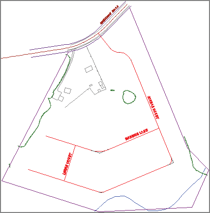
Figure 5-1: A single-line drawing of the subdivision roads (in red)
Civil 3D alignments are designed specifically for the task of representing the initial single-line version of a linear design feature. They are also used to establish the backbone of linear designs such as roads, railroads, channels, and pipelines. The lines, arcs, and spirals that make up an alignment have the ability to interact with one another. This enables you to edit part of the alignment and have the other parts fix themselves automatically. Also, other design objects such as profiles, sections, and corridors can be built around alignments. You’ll learn more about these other design objects later in this book.
Creating Alignments from Objects
A common way of creating an alignment is to use the basic AutoCAD® software geometry that’s already in the drawing. You may be using someone’s “sketch,” or maybe you’ve chosen to draw the initial version of the layout this way because of the simplicity of the AutoCAD tools. Whatever the case, Civil 3D makes it fairly easy to convert simple AutoCAD entities into alignments.
Exercise 5.1: Create Alignments from Objects
In this exercise, you’ll create alignments from polylines in the drawing that represent road centerlines.
- Open the drawing named
Alignment from Objects.dwglocated in theChapter 05class data folder.Because alignment design is strictly a 2-D type of design, the drawings in this chapter aren’t set up with multiple viewports.
- On the Home tab of the ribbon, click Alignment ⇒ Create Alignment From Objects.

- When the command line prompts you to select an object, click the longest magenta polyline, labeled Jordan Court.
- Press Enter.
A black arrow should appear on the polyline, indicating the program’s guess at the direction of the alignment.
- If the arrow is pointing toward the south, press Enter. If it’s pointing north, press R and then press Enter.
Believe it or not, the choice here is very important. The direction of the alignment will affect the configuration and labeling of many more components of this design as it progresses.
- In the Create Alignment From Objects dialog box, do the following:
- For Name, enter Jordan Court.
- For Type, verify that Centerline is selected.
- For Site, verify that <None> is selected.
- For Alignment Style, verify that Proposed is selected.
- For Alignment Label Set, verify that _No Labels is selected.
- Uncheck the box next to Add Curves Between Tangents.
- Verify that the box next to Erase Existing Entities is checked.
- Click OK.
- Click the newly created alignment, and then click one of the magenta polylines.
Notice how the polyline grips are different from the alignment grips (see Figure 5-2).
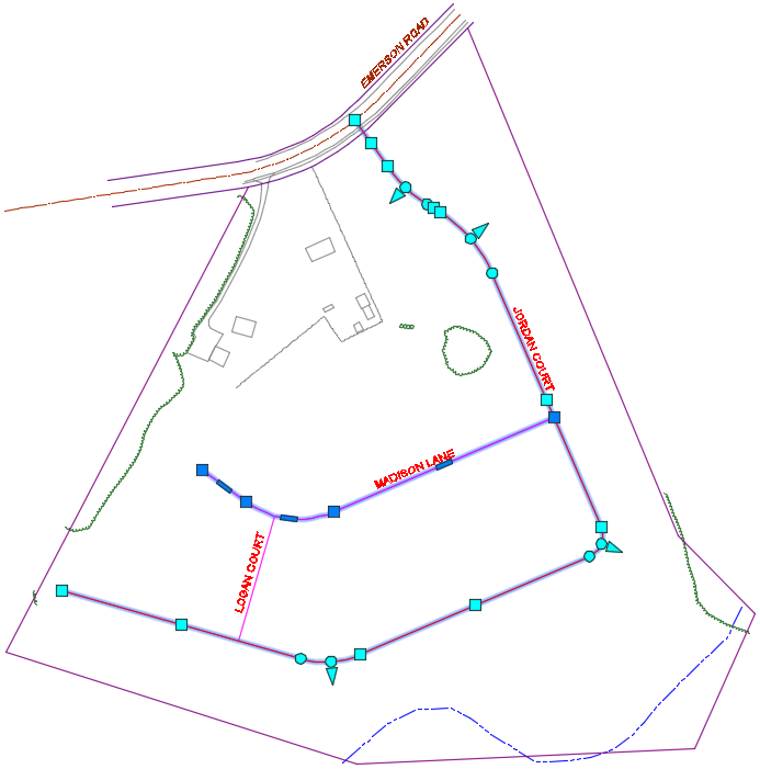
Figure 5-2: The object with the dark blue grips is a polyline, and the object with the light blue grips is an alignment. Alignments have more types of grips that enable more geometric editing functionality.
- Experiment with moving the grips, and compare the behavior of a Civil 3D alignment with the behavior of a polyline.
- Repeat steps 2 through 6 to create the Madison Lane and Logan Court alignments.
- Save and close the drawing.
You can view the results of successfully completing this exercise by opening Alignment from Objects - Complete.dwg.
Creating Alignments Using the Alignment Creation Tools
Many times you won’t have geometry in the drawing that you can simply convert to an alignment. In these cases, you can use the Civil 3D Alignment Creation Tools to create alignments from scratch. The Alignment Creation Tools are housed in Civil 3D’s version of a toolbar and consist of a comprehensive set of commands to create and edit the lines, curves, and spirals that make up an alignment.
Exercise 5.2: Create Alignments Using the Alignment Creation Tools
In this exercise, you’ll create alignments using the Alignment Creation Tools. You’ll draw the alignments according to reference geometry, dimensions, and other information that has been provided for you.
- Open the drawing named
Alignment Creation Tools.dwglocated in theChapter 05class data folder. - Examine the blue geometry and accompanying dimensions and notes.
This geometry is described in detail in the sidebar “Using Temporary Geometry.”
- On the Home tab, click Alignment ⇒ Alignment Creation Tools.

- In the Create Alignment – Layout dialog box, enter Jordan Court for Name, and click OK.
- On the Alignment Creation Tools toolbar, click the black triangle on the first button on the left to expand it downward (see Figure 5-3). Then click Tangent-Tangent (With Curves).

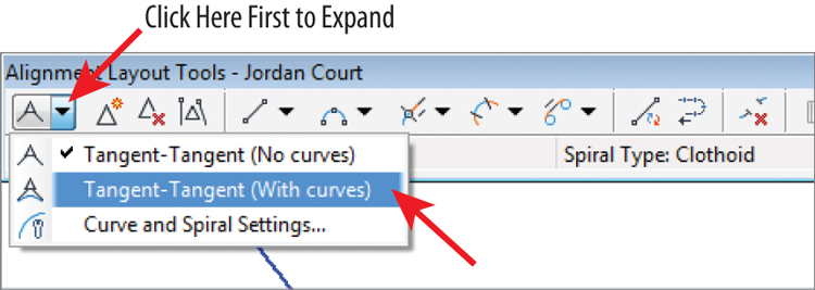
Figure 5-3: Selecting the Tangent-Tangent (With Curves) command
- Snap to the center of the circle marked A.
- Snap to the centers of circles B through E (skip over circles F and I), and press Enter. The Jordan Court alignment is created.
- To create the Madison Lane alignment, repeat steps 3 through 7, entering Madison Lane for Name and using circles F through H.
- To create the Logan Court alignment, repeat steps 3 through 7, entering Logan Court for Name and drawing it from circle I perpendicular to the Madison Lane alignment.
- Save and close the drawing.
You can view the results of successfully completing this exercise by opening Alignment Creation Tools - Complete.dwg.
Editing Alignments
Of course, nobody gets it right the first time. As a general rule, you’ll find yourself laying things out about 10 percent of the time and spending the remaining 90 percent making edits. That’s totally OK; it’s the way Civil 3D was designed to be used. In fact, it’s highly recommended that you do a rough layout of the basic design elements at the beginning of a project and then spend the rest of the time adjusting, refining, and improving that initial layout until it’s the way it needs to be. This is also a great approach because it matches up with the general nature of land-development designs, which typically change frequently throughout the life of the project.
Editing Alignments with Grips
As you learned in the first section of this chapter, alignments are different. They’re smarter and more sophisticated than basic AutoCAD entities. They have more types of grips, and the way they respond to geometric changes is more intelligent. You can leverage this to make quick visual edits to your alignment without ever typing a number or entering a command.
Exercise 5.3: Experiment with Alignment Grips
In this exercise, you’ll experiment with the different grips that can be used for editing alignments.
- Open the drawing named
Graphical Editing.dwglocated in theChapter 05class data folder. - Click the Jordan Court alignment to display its grips. Click the upright triangular grip on the second curve, and move your cursor to a new location without clicking the new location.
This grip is located at the PI. As you move it, the curve always remains tangent and the radius of the curve remains constant (see Figure 5-4).
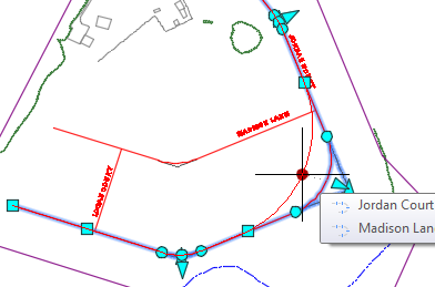
Figure 5-4: Moving a PI grip
- Press Esc, and click the circular grip at either end of the curve. Move your cursor to a different location without clicking.
These grips are located at the PC and PT. As you move them, the radius changes and tangency is maintained at both ends of the curve (see Figure 5-5). They can be used to graphically set the exact beginning point or ending point of a curve.
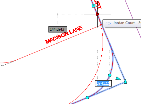
Figure 5-5: Moving a PC or PT grip
- Press Esc, and click the circular grip at the midpoint of the curve. Move your cursor to a different location without clicking.
This grip is located at a pass-through point, and it forces the curve to pass through that point while maintaining tangency at both ends. This is accomplished by changing the radius of the curve (see Figure 5-6). You can use this grip to make the curve pass through a specific point.
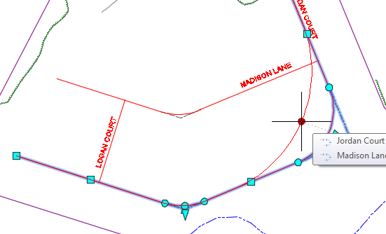
Figure 5-6: Moving the pass-through point grip
- Press Esc, and click the triangular grip located near the midpoint of the curve. Move your cursor to a different location without clicking.
This grip controls the radius of the curve while maintaining tangency at both ends of the curve (see Figure 5-7).
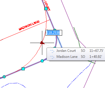
Figure 5-7: Moving the radius grip
- Press Esc, and click the square grip at the end of the Jordan Court alignment. Move your cursor to a different location without clicking.
This type of grip is located at either the beginning or the end of the alignment. As it’s moved, the geometry adjacent to it responds. In the case of this alignment, the curve just before the endpoint changes the locations of its beginning and ending points to remain tangent at both ends (see Figure 5-8).
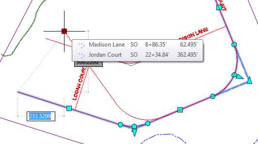
Figure 5-8: Moving the start point or endpoint grip
- Press Esc, and click the square grip located at the midpoint of the last tangent in the alignment. Move your cursor to a new location without clicking.
This grip moves the tangent while maintaining its orientation in the drawing. Adjacent geometry responds as needed to meet its geometric rules. In the case of this alignment, the PI to the left of this grip changes location, and the curve to the right changes its beginning and ending points to remain tangent (see Figure 5-9).
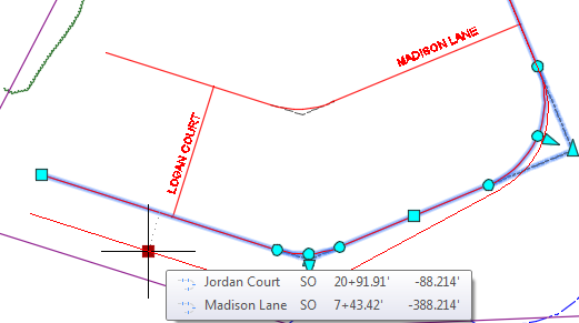
Figure 5-9: Moving the tangent midpoint grip
- Close the drawing without saving.
Because this drawing was not changed, there is no “completed” version of the drawing.
Editing Alignments Using the Alignment Layout Tools
Grips are wonderful tools to edit geometry that is already there, but what if you need to add a PI or draw a curve? For that, you need the Alignment Layout Tools toolbar (see Figure 5-10). This toolbar is the same one you used initially to lay out the alignment.
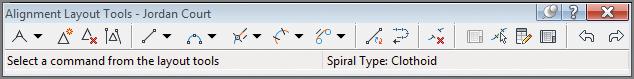
Figure 5-10: Alignment Layout Tools toolbar
Exercise 5.4: Apply the Alignment Editing Tools
In this exercise, you’ll edit the Jordan Court alignment using the Alignment Editing Tools. The goal is to create a perpendicular intersection where Jordan Court meets Emerson Road.
- Open the drawing named
Editing Tools.dwglocated in yourChapter 05class data folder. - Click the Jordan Court alignment, and then click Geometry Editor on the ribbon.

This opens the Alignment Layout Tools toolbar.
- On the Alignment Layout Tools toolbar, click Insert PI. Then snap to the center of the circle marked A.

- Click Delete Sub-entity, and then click the curve at the PI marked B.

- Click the tangent between A and B to remove it as well. The alignment should now look like Figure 5-11.
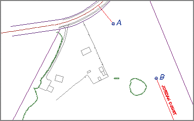
Figure 5-11: Alignment after removing a tangent and a curve
- Expand the curve button, and click More Floating Curves ⇒ Floating Curve (From Entity End, Radius, Length).

- Click the tangent near point A.
- Type O and press Enter to indicate a counterclockwise direction.
- Type 100 (30) and press Enter to provide the radius.
- Type 100 (30) and press Enter to provide the curve length.
A short curve is placed at the end of the tangent.
- On the Alignment Layout Tools toolbar, expand the curves button, and select Free Curve Fillet (Between Two Entities, Radius).

- Click the curve you just created in the previous steps.
- Click the red tangent that begins at point B.
- Press Enter to indicate that the solution is less than 180 degrees.
- Type R and then press Enter to indicate that it’s a reverse curve.
- Type 100 (30) and press Enter to provide the radius. Press Enter to end the command.
The new curve is created in the drawing, as shown in Figure 5-12.
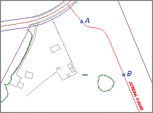
Figure 5-12: Alignment after the addition of a reverse curve
- Save and close the drawing.
You can view the results of successfully completing this exercise by opening Editing Tools - Complete.dwg.
Editing Alignments Numerically
At times, you may want to adjust your design by telling Civil 3D the exact dimension of a portion of the alignment. This can be done in one of two different ways. The first is Alignment Grid View, which opens a tab in Panorama. This tab shows the geometry of the alignment in table form and enables you to edit some of the values to adjust the design.
Exercise 5.5: Edit Alignments Using Alignment Grid View
In this exercise, you’ll edit the Jordan Court alignment using the Alignment Grid View command.
- Open the drawing named
Alignment Grid View.dwglocated in theChapter 05class data folder. - Click the Jordan Court alignment, and then click Geometry Editor on the ribbon.

- Click Alignment Grid View to open the Alignment Entities tab and display the tabular version of the alignment geometry, as shown in Figure 5-13.

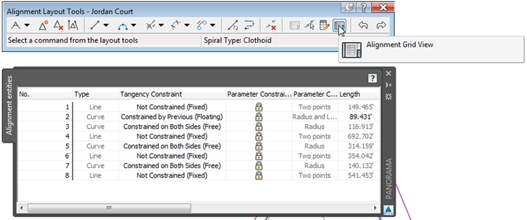
Figure 5-13: The Alignment Entities tab of Panorama showing the tabular data of the alignment
- For the Radius values for items 2 and 3, type 150 (45) and press Enter.
Notice that the alignment updates automatically in the drawing.
- Save and close the drawing.
You can view the results of successfully completing this exercise by opening Alignment Grid View - Complete.dwg.
Another method for editing the alignment design numerically is referred to as component-level editing. With this approach, you open the numerical data for a piece of the alignment (such as a line, curve, or spiral) in a separate window. You do so by clicking the Sub-entity Editor button on the Alignment Layout Tools toolbar and then using the Pick Sub-entity tool to choose the part of the alignment you want to edit.
Exercise 5.6: Edit Alignments Using Component-Level Editing
In this exercise, you’ll edit the Jordan Court alignment using component-level editing.
- Open the drawing named
Component Level Editing.dwglocated in theChapter 05class data folder. - Close Panorama if it’s open. Click the Jordan Court alignment, and then click Geometry Editor on the ribbon.

- Click Sub-entity Editor on the Alignment Layout Tools toolbar to display the Alignment Layout Parameters dialog box. (This dialog box is blank when it first appears.)

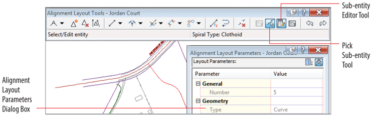
Figure 5-14: The Sub-entity Editor Tool, Pick Sub-entity Tool, and Alignment Layout Parameters dialog box
- Click Pick Sub-entity (see Figure 5-14), and then click the curve at the 90° bend on Jordan Court.

- Type 50 (15) for Radius, and press Enter.
The curve in the drawing updates automatically.
- Close the Alignment Layout Parameters dialog box and the Alignment Layout Tools toolbar.
- Save and close the drawing.
You can view the results of successfully completing this exercise by opening Component Level Editing - Complete.dwg.
Applying Design Criteria Files and Check Sets
When you’re laying out a design, how do you know whether you’re doing it right? What should the curve radii be? Should there be a minimum tangent length between curves, or is it OK to have back-to-back curves? How does the expected speed of traffic affect the answers to these questions?
The answers to these types of questions can differ, depending on the project. For road design, the government entity that accepts responsibility for the road is most likely calling the shots when it comes to design standards. That may be the state Department of Transportation (DOT), county planning commission, or even the community homeowners association. In other cases, you may be designing roads or other linear features on private property that isn’t governed by any official design standards. In this case, you’ll have to utilize your knowledge and experience to create the best design. Whether the design standards come from you or someone else, it’s helpful to have tools that ensure that your design meets the requirements assigned to it.
Design criteria and check sets are two ways of telling Civil 3D what your design standards are and asking Civil 3D to tell you when you’ve violated those standards by displaying a warning symbol (see Figure 5-15). These two features are customizable, so you can use them to represent any standard or combination of standards that is necessary.
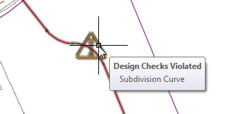
Figure 5-15: Tooltip relaying details about a design check set violation
Applying Design Check Sets
A design check set is a collection of one or more design checks. There are four types of design checks: line, curve, spiral, and tangent intersection. When a design check set is applied to an alignment, Civil 3D flags any violations with a triangular yellow shield marked with an exclamation point. You can hover over the shield to get more information about the violation, as shown previously in Figure 5-15.
Exercise 5.7: Apply a Design Check Set
In this exercise, you’ll apply a design check set to the Jordan Court alignment and then make edits based on the results.
- Open the drawing named
Design Check Set.dwglocated in theChapter 05class data folder. - Click the Jordan Court alignment, and then click Alignment Properties on the ribbon.

- In the Alignment Properties dialog box, click the Design Criteria tab.
- For Design Seed, type 25 (40), and press Enter.
- Check the box next to Use Criteria-Based Design.
- Uncheck the box next to Use Design Criteria File.
- Verify that Use Design Check Set is checked, and select Subdivision.
- Click OK to close the Alignment Properties dialog box. Press Esc to clear the grips on the alignment. You should see three yellow warning symbols in the drawing, as shown in Figure 5-16.
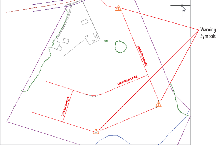
Figure 5-16: Warning symbols indicating design check set violations within the alignment
- Zoom in to the curve farthest to the south. Hover your cursor over the yellow shield.
A tooltip should appear, indicating that the Subdivision Curve design check has been violated.
- Click the alignment to display its grips; then click the circular grip at the midpoint of the curve, and drag it northward to increase the radius of the curve. Repeat as necessary until the shield disappears.
- Click the Jordan Court alignment, and then click Geometry Editor on the ribbon.

- On the Alignment Layout Tools toolbar, click Alignment Grid View.

Notice the yellow shields in the No. column as well as the bold values in the Radius column and several other columns (see Figure 5-17). This tells you which items have violations as well as which specific values are causing them.
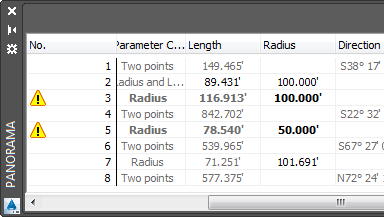
Figure 5-17: Warning symbols in Panorama indicate design check set violations.
- For the Radius value of item 3, type 150 (45), and press Enter.
The shield should disappear, and the bold values for item 3 should now show in normal print. The Radius value for item 5 will remain at 50' (15 m).
- Save and close the drawing.
You can view the results of successfully completing this exercise by opening Design Check Set - Complete.dwg.
Applying Design Criteria Files
Design criteria files are another way of having Civil 3D check your design as you go. From an end-user standpoint, there isn’t much difference between a design check set and design criteria file: they’re both something you assign to your alignment so that certain design parameters can be checked. From a setup standpoint, they’re quite different. Design check sets are a group of design checks that are relatively simple and are managed through the Settings tab of the Toolspace. A design criteria file is a single file, and it’s potentially much more sophisticated. There is a special tool for editing design criteria files called the Design Criteria Editor. Civil 3D comes with AASHTO design criteria files that can be used as is or copied and modified to meet local requirements. Autodesk also provides numerous country kits that include even more design criteria files that meet the requirements of various design authorities around the world.
Exercise 5.8: Apply a Design Criteria File
In this exercise, you’ll apply a design criteria file to the Jordan Court alignment and then make edits based on the results.
- Open the drawing named
Design Criteria Files.dwglocated in theChapter 05class data folder.Note that currently only one warning symbol is shown for the Jordan Court alignment.
- Click the Jordan Court alignment, and select Alignment Properties on the ribbon.

- Click the Design Criteria tab. Check the box next to Use Design Criteria File.
- Click the button to the right of the file path, and select the file named
Autodesk Civil 3D Imperial (2011) Roadway Design Standards.xml(Autodesk Civil 3D Metric (2011) Roadway Design Standards.xml). Click Open. - Uncheck the box next to Use Design Check Set.
- Click OK, and press Esc to clear the grips.
New warning symbols appear on the first, second, and fourth curves (the one on the third curve was there previously). As you can see, the design criteria file is a bit more stringent than the design check set of the previous exercise.
- Hover your cursor over the warning symbol farthest to the north.
- Select the alignment, and click Geometry Editor on the ribbon.

- Click Alignment Grid View on the Alignment Layout Tools toolbar.

- Note that the minimum radius is listed in Panorama. Change the radius of items 2, 3, and 7 to 155 (48).
Do not edit item 5; it should remain set to 50' (15 m).
- Close Panorama, and observe the change to the alignment.
- Save and close the drawing.
You can view the results of successfully completing this exercise by opening Design Criteria Files - Complete.dwg.