So far in this book you have modeled a lighthouse, chess piece, sundial, and part of a table and house using the Match Photo feature in SketchUp. By going through each chapter and designing the models, you are starting to get use to the 3D modeling and printing process. If you have reached this stage in the book and still have not quite gotten your hands trained for modeling, fear not. It can take a couple of months to develop a modeling mind-set and get your hands familiar with the modeling process. Keep your head high, and take things one step at a time. Sooner or later, you will get it.
In this chapter, you'll step things up a notch and design symmetrical objects. Modeling symmetrical objects can be very exciting, and you will get a feel for it starting halfway in this chapter. The great thing about modeling symmetrical objects is that you need to model only half of them. The other half of the model can be easily duplicated. In this chapter, you'll apply many of the same techniques you have learned throughout the book to create a symmetrical model.
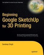
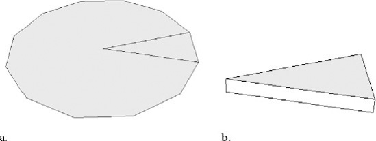
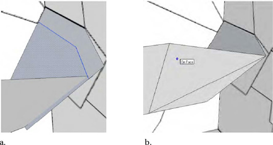
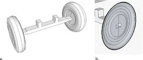
In your daily life, you probably have encountered both symmetrical and asymmetrical objects. So, what are some examples, and what are the differences between both these types of models? Symmetrical objects when split in half look identical on both sides. Examples include cars, chairs, buildings, animals, and cups. There are endless symmetrical models you can find in the world. Symmetrical objects can also come in two formats. There are bilateral and radically symmetrical models. Objects that have bilateral symmetry are identical on both halves (Figure 8-1a). Objects that have radial symmetry can be divided into quadrants where each quadrant is similar to the first (Figure 8-1b). Radial symmetrical objects include umbrellas and staircases.
Objects that do not fall in the bilaterally or radically symmetric category are considered asymmetrical. Examples of asymmetrical objects include trees, houses, land, and rocks. Constructing these types of models requires more time since there are no sides to the object that are exact duplicates.
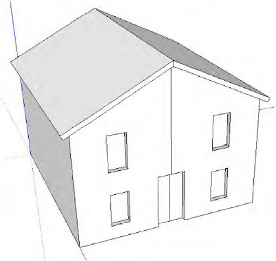
Let's go through two examples demonstrating the steps for constructing a bilaterally and radically symmetrical model. With the first example, you'll learn about bilateral symmetry by taking half a house and constructing a complete model. In the second example, you'll learn about radical symmetry by designing a staircase.
Creating a bilaterally symmetrical object can be broken down into six easy-to-follow steps:
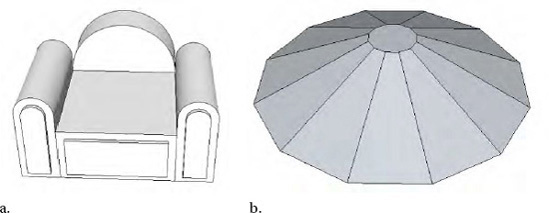
The first step is to construct only half the model. The model in Figure 8-2 shows only half a house designed in SketchUp.
Make the model into a component. To do so, highlight the entire model, right-click the model, and from the drop-down menu select Make Component.
Then create a copy of the component. Select the Move/Copy tool, and click a corner of the house. Press Ctrl once on your keyboard. The cursor will show a + sign alongside the cursor, indicating the model is ready to be copied. Drag the model, and click again to release it.
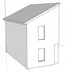
Now all you need to do is flip the copy of the model. You can use the Scale tool and invert the copy, or you can use Flip Along. Right-click the copy of the model, and from the drop-down menu select Flip Along. Select along the x-axis (red), y-axis (green), or z-axis (blue) (Figure 8-3).
Using the Move/Copy tool, drag the two halves together to join the two components (Figure 8-4).
Since both halves are a component, changes in one will appear in the other. The model looks great, but there is something not quite right. Do you see the problem? Yes, there is a line through the middle of the model. To hide the line, double-click one component to enter it. Right-click the line, and from the drop-down menu select Hide. The lines are hidden, but the model is still in two halves. I don't think Shapeways will print two halves of a model. In the next section, you will see how to combine the halves for 3D printing on Shapeways.
The process to model a radically symmetric object is not different or difficult at all. Radially symmetric objects are made of quadrants, and each quadrant is the same as the first. An example of a radially symmetric object is a staircase. Let's see how a staircase can be modeled in SketchUp.
The first step is to draw a polygon. Select the Circle tool, and click the center axis. Type 12s, hit Enter on your keyboard, and then drag the mouse out to draw the 12-sided polygon. I chose 12 sides, but you can draw as many sides as you want. In this example, there will be 12 steps that make up the staircase.
Draw a triangle using one of the edges of the polygon as a side of the triangle using the Line tool (Figure 8-5a).
Delete all the other edges of the polygon, leaving behind only the triangle. You will use this triangle to create all the other steps in the staircase.
Extrude the triangle using the Push/Pull tool to add width (Figure 8-5b).
Select the triangle, and turn it into a component. As a component, you can make copies of each step easily. Also, in case you edit a step, all instances of the step will also apply those edits.
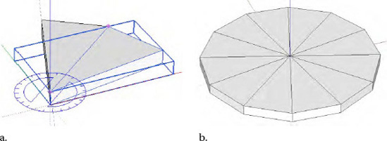
Using the Rotate tool, click the vertex of the triangle, and hit Ctrl once on your keyboard. The cursor will show a + sign. Then click a second time on the left-outer corner of the triangle. Now rotate the triangle, making a copy that sits right next to the original (Figure 8-6a). Then type 12x, and hit Enter. This will create 12 copies of the triangle alongside each other (Figure 8-6b).
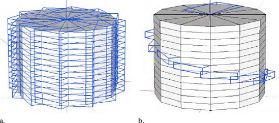
Select all copies of the triangle, and then create a copy using the Move/Copy tool on top of the first layer of the model. Remember to press Ctrl before making a copy. After the first copy, type 12x, and hit Enter on your keyboard. This will create 12 copies one on top of the other (Figure 8-7a).
Then select all the triangles from top to bottom diagonally while holding the Ctrl key (Figure 8-7b). Holding the Shift key on your keyboard, select the entire model, and then press Delete on the keyboard. This will leave behind a copy of the triangle you initially had selected while creating your radially symmetric staircase (Figure 8-8).
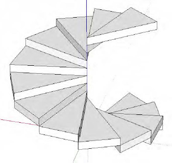
In this example, there is no need to hide the edges of the triangle since each triangle is above the others on a different plane. Using a similar approach, you can create other types of models. There are umbrellas and starfish. Give this a try to see what you can make.
This chapter is not over yet; it's time to get down to business. We have left the best model for last. You will construct an armored car in Google SketchUp, also known as the BA-64B armored car, which you then will upload for 3D printing on Shapeways. Unlike the models you constructed in the previous section, there are a few extra steps to consider when developing symmetrical models for 3D printing on Shapeways.
To design the BA-64B armored car, you will use a drawing to assist you along the way. You can download a copy of the drawing (Figure 8-9) from the book's catalog page on Apress.com.
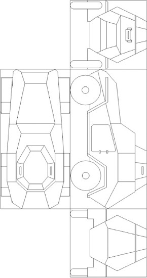
To construct your model of the armored car, you need only four views (even fewer if you're a really good modeler). You will be using the side, bottom, front, and back views. You won't be tracing every detail in each view when constructing our model. You will use the views as a guide to construct parts of the model.
Using Microsoft Paint or any other image-editing software, crop the four individual views, and save them on your computer as separate image files in JPEG or PNG format. Name them A, B, C, and D for easy reference.
Make sure to crop just the image of the car and nothing more or less. This way it will be easier to align the images in SketchUp. If you are confused, don't worry. This will start to make sense when you upload the images into SketchUp.
In SketchUp, select File

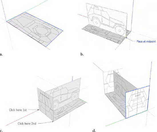
Attached to the cursor will be the bottom view. Drag your cursor along the red or green axis, and then click the center axis. This will make sure the image is on the green and red axes. Drag your mouse outward to enlarge the bottom view, and click once more to lock the image in place (Figure 8-10a).
Now import the side view into your model. Click the Midpoint of the bottom view, and drag the cursor enlarging the image. Then click the opposite end of the bottom view (8-1-10b). If the image isn't perpendicular to the bottom view, use inferencing to align the image.
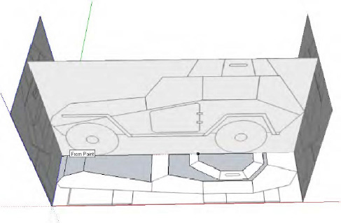
Import the back view, and attach it to the back of the side and bottom view. Click once to attach the image, and drag the cursor to enlarge the image. Click a second time to fix the image in place (Figure 8-10c). Repeat the same process for the front view. Once you are all done, your view should be aligned and ready for tracing (Figure 8-10d).
Note
If it's easier, you can enter the length of the photo after the first click. This will give you an exact match without having to drag and enlarge the image. Also for ease of use, rotate the views so all the surfaces are facing inward. When a trace appears on the opposite side of a view, the surface is flipped. This will save you the frustration of having to flip the views later.
Before continuing, save the model, and give it the file name
BA-64B_Version_1. For a model this complicated, it's important to save multiple copies in case you need to go back to an original and make changes.
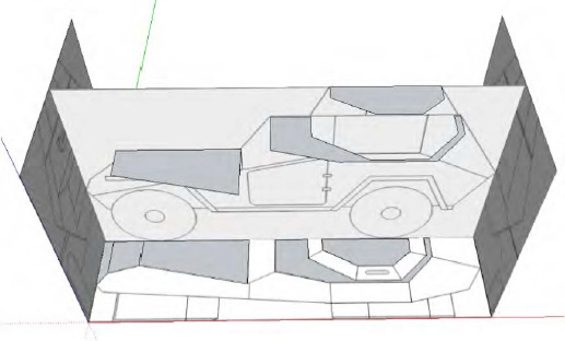
Now that all your views are aligned in SketchUp, you are ready to trace your model. You will only be tracing the outer body of the armored car. Once you have the outer body of the model designed, you will then import the wheels and axle to complete the model by the end of the chapter.
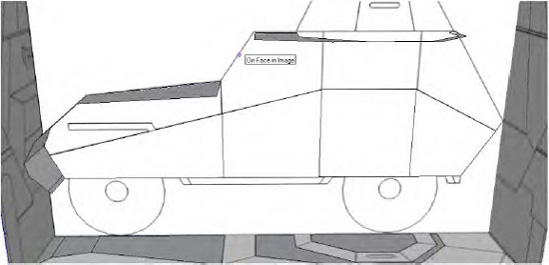
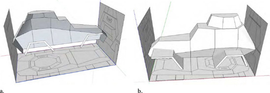
To get started, trace the outline of the top view, as shown in Figure 8-11, using the Line tool. You have not traced the entire top view of the image. You only traced the flat surfaces of the model and the hood. You will create the other surfaces in a later section by looking at the side view.
Now select the Move/Copy tool, copy each surface, and align it with the side view. The two surfaces at the end will be raised later (Figure 8-12). Notice the surface over the hood is not in alignment with the side image. You will need to align this to the side image.
Select the surface over the hood, and using the Rotate tool, move it so that it is in parallel with the slant of the hood. Now the surface of the hood is in alignment (Figure 8-13).
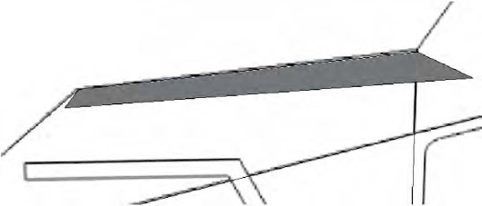
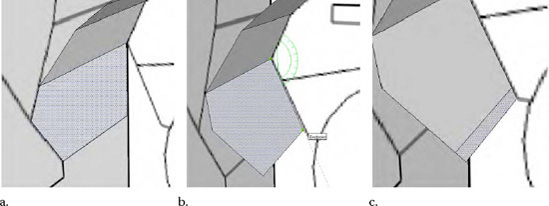
You now raise a copy of the surface that attaches to the front of the hood using the Move/Copy tool and align it to the side view (Figure 8-14a). Then rotate it to match the slant of the side view (Figure 8-14b). If the surface is short compared to the side view, then, using the Line tool, draw in the extra surface (Figure 5-14c).
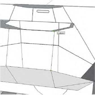
The front of the model isn't complete yet. Using the Line tool, trace in the surface on top of the front grill. You will need to use the front and side views as reference to draw the lines. Figure 8-15 shows what the surface should look like after you are done.
To draw the grill, trace the front view of the model (Figure 8-16a). Using the Rotate tool, rotate the surface, and align it with the side view (Figure 8-16b). If the grill is short compared to the side view, extend it using the Line tool (Figure 8-16c).
Tracing the side and back views is not difficult at all. You will be applying the same techniques used when you traced the top and front views in the previous section. Again, you will be using the Line, Move/Copy, and Rotate tools.
To trace the side view, follow these steps:
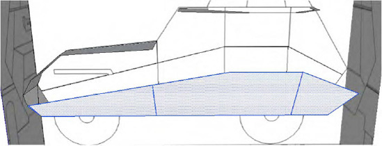
1. Use the Line tool, and trace the bottom half of the side view, as shown in Figure 8-17. Also draw in the horizontal lines defining the different surfaces of the model. You will be using these lines as a guide to draw in the other lines later.
7. Now as before, using the Move tool, move the side surface, and align it with the front image.
Note
At this stage, you can also trace in the door. It is easier to do it now then later. Later I will be showing you how to add the door using a different method that requires more steps but is a great learning experience. To trace the door, select View
8. Using the Rotate tool, rotate the side surface of the model. To move and rotate the surface, remember to select the entire surface and not just an edge, as shown in Figure 8-18.
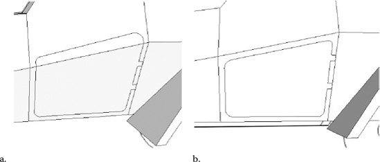
As you did to trace the front view, you can take similar steps to trace in the back view using the Line tool. It is a tough model to draw in SketchUp, so take your time. If something doesn't feel natural while tracing, experiment to see what works best.
To construct the back surface, follow these steps:
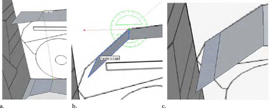
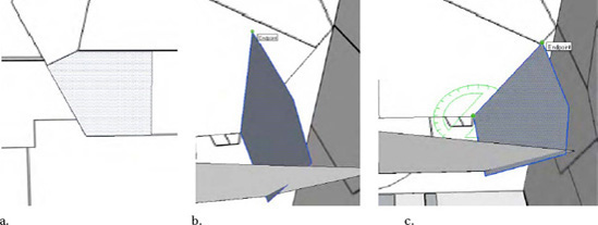
Trace the surface on the back of the armored car using the Line tool (Figure 8-19a). Then select the entire surface, and using the Move tool, align it with the edge of the side surface (Figure 8-19b).
Using the Rotate tool, rotate the surface so that it is in alignment with the side surface (Figure 8-19c).
Looking at the model, closely notice that the surfaces are short and the back surface overlaps with the side surface.
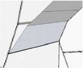
Use the Line tool, and extend the back surface of the model (Figure 8-20a). Then delete and redraw the side surface of the model (Figure 8-20b).
Notice SketchUp did not automatically fill the side with a single surface, so a diagonal line was created to complete the design. This is common actually when you design models of this type. The surface is not perfectly flat, and SketchUp uses two surfaces to connect the cap. This will be the case when working with surfaces that do not fall on the x, y, or z plane.
Now that you are done with creating the back surface, you are ready to add the missing gaps in the model. All the surfaces you have created so far were leading up to this stage. You will now be using those surfaces to assist you in filling in the gaps between those surface.
Use the Line tool, and draw lines from the side surface to the middle surface (Figure 8-21). Drawing these lines will automatically create a surface between the two. For surfaces that do not show a surface after adding the lines, try adding a diagonal line. Sometimes these surfaces consist of multiple lines.
Note
Sometimes multiple lines are needed when an edge is made of more than one line. To solve the problem, delete the edge and redraw a single line. This may eliminate the need to redraw multiple lines.
As you connect each layer, the frame of the car will slowly come to form (Figure 8-22a). Have patience here; it might take a couple of tries to get everything right, so save a backup in case something goes wrong.
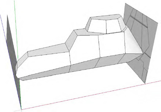
Hide the side view and rotate the model, and you will notice on the other side there is a hollow shell (Figure 8-22b). If there are any surfaces or lines within the shell, select and delete them. They may have been left behind in the process of constructing the model.
To get rid of the extra diagonal lines you created to draw in the surfaces, you can now hide them. Select the Eraser tool, and while holding down the Ctrl key, select each line in the model you want to hide.
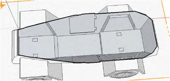
Notice that some of the surfaces are facing into the model. Right-click the surface, and from the drop-down menu select Orient Faces. This will automatically orient all faces in the direction of the selected surface. This saves you time by not having to reverse each face/surface individually. Figure 8-23 shows the model after you are all done. The model is now much cleaner, and you can see all the surfaces that define the sides of the model.
You are almost done, but there are just a couple more things to add to the armored car before it will be ready for 3D printing. Next you'll add the fenders of the model.
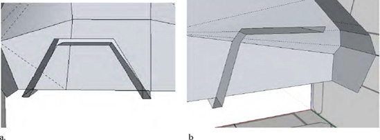
Use the side image, and trace the fenders of the car (Figure 8-24a). After tracing the fender, hide the side image.
Using the Push/Pull tool, extrude the trace into the side surface of the model and out the other end (Figure 8-24b). Extrude it all the way to the edge of the front image.
The fenders are not completely joined to the frame. You need to connect them before continuing.
Use the Line tool, and trace the intersection of the fender with the body of the car (Figure 8-25). Also turn on hidden geometry. Since there are multiple surfaces that define the body of the car, it's important that you draw lines on those surfaces and not in a tangent.
After drawing in the edges, delete the fender surfaces within the model.
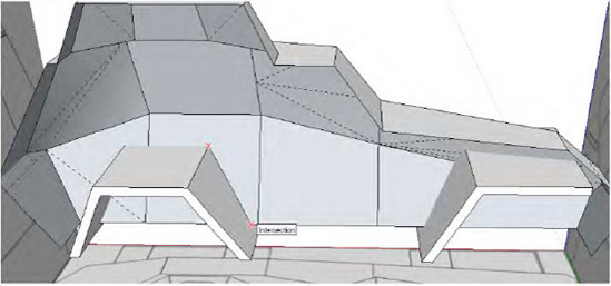
After you are all done, you should see an opening into the fender from the inside the model (Figure 8-26). This opening will be filled in with material when you send the model off for 3D printing to Shapeways. Make sure there is an opening, or you will be presented with an error during the upload process.
Now that the fenders are in place, you will add some detail to the model such as the door and add windows in the armored car. There is actually a lot of additional detail that you could add to the model, but the process is long, so I will leave it up to you.
To model the door, follow these steps:
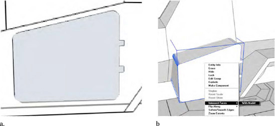
Trace the door and window of the model on the images as you did for the fender (Figure 8-27).
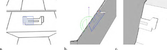
After tracing the door of the armored car, select the entire trace of the door, and convert it into a group. Extrude the surface using the Push/Pull tool. Then right-click the group, and from the drop-down menu, select Intersect Faces
Select the grouped door, and hit Delete. What is left behind is just the trace. Notice the trace is slightly off from its original location. Since there is a slant in the surface on which the trace was created compared to the trace on the image, the door does not exactly line up with the model (Figure 8-28a).
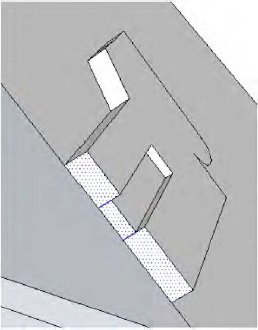
Using the Line tool, retrace the parts of the door in its correct location, and delete the lines in the wrong location. Once the door has been created, extrude it.
To draw the windows for the armored car, you can apply the same techniques as you did when drawing the door. But you can also trace the window and move it onto the surface of the car.
In Figure 8-29a, you have traced the front window of the car on the front view.
Use the Move tool, and move the trace onto the model. Use the Rotate tool to rotate the trace to match the slope of the front surface (Figure 8-29b). The window was extruded slightly to add definition (Figure 8-29c).
After adding all the details of the model, rotate the model, and make sure to delete all the internal remains, surfaces, and lines created as a result of adding the extra detail. Make sure to zoom into the model and delete any extra surfaces created. From the Figure 8-30, you can see when adding the window to the model it creates surfaces on the inner side of the model. Select and delete these surfaces.
You are about to see what the model looks like in its entire form, which is an exciting moment for a designer.
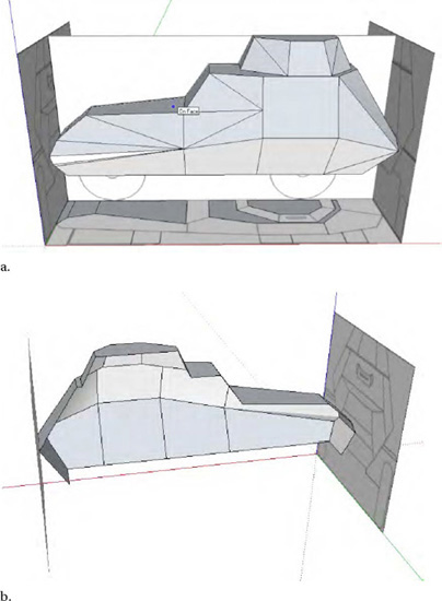
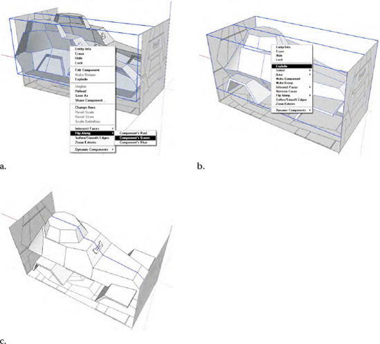
To complete the model, group the side of the model you just constructed, and then create a copy. Right-click the copy, and select Flip Along to flip its direction (Figure 8-31a). Drag the models together so they intersect and are in alignment with each other.
Select both models, and then right-click and select Explode (Figure 8-31b). This will combine both models into one. All you will be left with is a line down the middle of the model (Figure 8-31c).
Select the line down the middle, and delete it from your model. Now all that is left is to add the axle and wheel for the model.
Note
If the line down the middle of the model is not perfectly straight and has a few gaps, try deleting the line and redrawing the surface combining the two halves.
At this stage, you can go ahead and design your own custom wheel and axle to attach to the body of the armored car, or you can use the one I developed. You can download example files for this book from the book's catalog page on the Apress.com web site. Look on the catalog page for a section entitled Book Resources, which you should find under the cover image. Click the Source Code link in that section to download the example files. In the Chapter 8 folder there is a file titled axle and wheel.
Select File
Select both wheels and axle, right-click, and select Explode. The tires are now attached to the axle.
Create a section plane cut through one of the wheels; notice there are some internal surfaces generated as a result of the intersection (Figure 8-32b). Delete those surfaces on both sides.
Create a component of the wheel and axle combination, and then create a copy. Place one set under the front fender and another under the back fender. Align the tires with the bottom and side images.
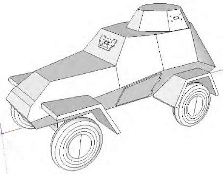
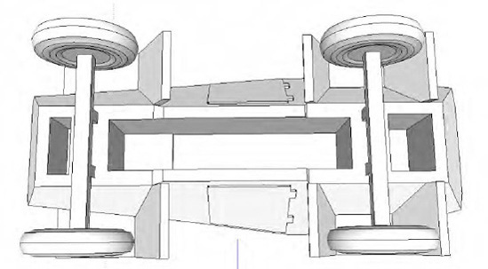
After the axle and wheels are aligned with the body, right-click, and select Explode so they attach with the entire model. The model should look like Figure 8-33 after you are all done.
Select Window
All that is left to do now is scale the model and upload it for 3D printing on to Shapeways. Also, remember to double-check your model for any errors. Refer to Chapter 4 where I discuss what errors you should look out for when developing a model for 3D printing.
To scale the model, use the Tape Measure tool, and measure the length of the model. Divide 3 inches by the length. Remember the length has to be in inches. The division will give you a scaling factor. Enter the scaling factor to scale the model you want the model to measure 3 inches in length after scaling.
The model now measures 1.7 inches (H) × 3.0 inches (L) × 1.5 inches (W). Try to see whether you can upload the model at this state. I uploaded the model successfully without any problems into Shapeways, but the model costs $44.21. For a model this small, $44.21 is really expensive. Also, there is one thing that must be fixed. The width of the axle isn't 2mm. This might break the axle during printing. Shapeways recommends that the minimum wall thickness of any surface be at least 2 mm. Extend the axle so it measures 2mm in width, and hollow out the insides of the model to reduce the volume and as a result the cost of the model, as shown in Figure 8-35.
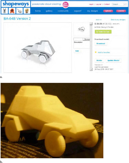
After reuploading the model, you see that the model costs only $39.59—a small savings (Figure 8-36a). You can further reduce the cost by scaling the model even smaller, but further alterations would need to be made to the model that could compromise the overall design and increase the design time. As a 3D designer, these are some of the challenges you will face. So, make sure to plan before starting your design. From this point on, the design is a personal preference, so I'll leave rest of the alterations to the model up to you. Figure 8-36b shows the model after 3D printing.
This chapter was quite an adventure. You started with an introduction to bilateral and radial symmetry. You learned how models can be designed with symmetry. Applying bilateral symmetry, you designed the BA-64B armored car. In the next chapter, you'll look at ways to share and sell the models you have designed in this book.