Chapter One
How can we build more efficient structures?

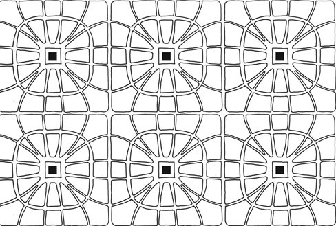
8. X-ray image of an Amazon water lily leaf showing an example of how robust structures are created in nature with a minimum of materials. The network of ribs stiffens the large area of leaf without adding excessive thickness
This observation captures the essence of biological structures. In technology, it is generally the shape that is expensive instead.20 Nature makes extremely economical use of materials, often achieved through evolved ingenuity of form. Using folding, vaulting, ribs, inflation and other means, natural organisms have created effective forms that demonstrate astonishing efficiency. The many manifestations of this in natural organisms provide a rich sourcebook of ideas for structures that could be radically more efficient than those found in conventional architecture.
Why is nature this way? The pressures of survival in all its varied aspects – finding sustenance, thermoregulating, mating and avoiding predation, among many other factors – have, over aeons, ruthlessly refined the structures and other adaptations that genetic mutation and recombination has created. The process continues, of course, but what we can observe in nature today is many of the best structures, evolved throughout the history of life on earth. The principle for architecture that emerges from observing is: less materials, more design. Exploring this paradigm, we will see an array of examples showing how minimum materials can be used to maximum effect.
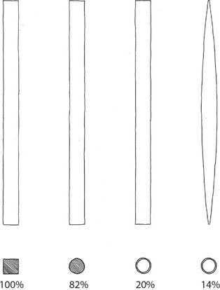
9.
Sketch showing how four equally stiff structural elements can be made with varying degrees of efficiency. By using shape and putting the material where it needs to be, it is possible to use only 14 per cent of the material of a solid square section (after work by Adriaan Beukers and Ed van Hinte in Lightness: The Inevitable Renaissance of Minimum Energy Structures)
Hollow tubes
Nature builds simply and economically, often meeting both goals simultaneously by making hollow tubes. Nature is abundant in examples that demonstrate this structural principle, such as human bones, plant stems and feather quills. If one takes a square cross-section of solid material with a side dimension 24 mm (fig. 9), it will have the same bending resistance as a circular solid section of diameter 25 mm with only 81.7 per cent of the material. Similarly, a hollow tube with only 20 per cent of the material of the solid square can achieve the same stiffness. In engineering terms, material has been removed from areas close to the neutral axis and placed where it can deliver much greater resistance to bending – achieving the same result but with a fraction of the material.
One plant in particular shows how hollow tubes can be applied at larger scales in nature. Bamboo species can reach 40 m in height. How do they maintain strength over this length? One of the ways in which a tubular element can fail under loading is through one side of the tube collapsing in towards the central axis, leading to overall buckling. Bamboo solves this by interrupting smooth tubular growth with regular nodes, which act like bulkheads (fig. 10). The nodes provide great resistance to structural failure, and are part of what has facilitated bamboo’s lofty accomplishments. Bamboo is, by strict taxonomy, actually a species of grass which has achieved such wild success that it resembles the scale of a tree. This plant’s solution seems to apply so widely that it begs the question: why aren’t more trees hollow tubes? The answer derives from the different forms that they strive to grow into: trees generally create a canopy of cantilevering branches, rather than the multiplicity of stems characteristic of grasses. Bamboo offers solutions to tubular structural elements, while trees offer a biomimic further solutions to holistic structural issues, since they face different pressures than grasses.

10.
The regular nodes in the stems of bamboo act like bulkheads stiffening the tube and preventing the normal way in which tubular structures fail
Trees: solid forms
Our understanding of trees and how lessons from them can be applied to engineering has developed enormously in recent years, particularly with the work of Claus Mattheck.21 In nature, biological forms follow a simple rule, which he describes as the axiom of uniform stress. In locations of stress concentration, material is built up until there is enough to evenly distribute the forces; in unloaded areas, there is no material. Trees also demonstrate the idea of optimised junction shapes that avoid stress concentrations and can adapt over time. The result approaches optimal efficiency, in which there is no waste material and all the material that exists is carrying its fair share of the load. By contrast, many steel and concrete structures are designed so that the most onerous load conditions (which only occur in specific locations) determine the size of the whole beam or column.
With his team at Karlsruhe Research Centre, Mattheck developed a design method that utilises two software processes (fig. 11) to create forms of biological design that are effectively identical to the refinements found in nature. The program allows designers to subject a rough structural computer model to the kind of forces that would be experienced in reality. These include snow, wind and seismic loading, as well as loads imposed by the building’s use. The first stage uses ‘Soft Kill Option’ (SKO) software to eliminate material in zones where there is little, or no, stress. Then a ‘Computer Aided Optimisation’ (CAO) program refines the shapes and, where necessary, builds up material at the junctions to minimise stress concentrations that could lead to failure. The designer is free to decide whether they like the output and find alternative ways to achieve structural integrity. Mattheck likens this process to starting with a roughly axed piece of timber, which is then carved to the near-final shape (the SKO stage) before being sanded and polished (CAO). The results can be surprisingly organic in form, and far more efficient than conventional structures.22 The designer Joris Larman used this to develop a number of elegant pieces of furniture and a bridge that is to be 3D printed and will span over a canal (fig. 12). We could do the same with buildings and achieve huge increases in material efficiency while producing more elegant and structurally legible forms.
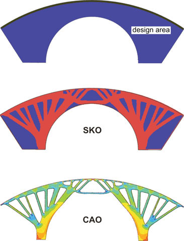
11. Diagram showing Claus Mattheck’s design refinement process using ‘Soft Kill Option’ (SKO) and ‘Computer Aided Optimisation’ (CAO) software
The key difference between trees and bones is that, in the former, material cannot be removed whereas in bone tissue it can be. Trees consequently grow as solid forms. This might seem surprising, given the hollowness of many bones. The explanation probably lies in the fact that there is not the same selective pressure for lightness in stationary trees as there is in animals that must move at speed to either catch, or avoid becoming, prey. Most of the bulk of a tree is dead material (only the outer layers remain alive), whereas bones are continually being reformed and recycled. One other possible explanation is that the solid core of trees functions to some extent as a compression core to resist the tension created by the outer sapwood, which grows in helical patterns up and around the trunk. This structural form has some similarities with Future Systems’ Coexistence Tower (fig. 13).

12.
3D-printed bridge by Joris Larman Lab demonstrating the expressive and material-efficient results of designing with SKO software
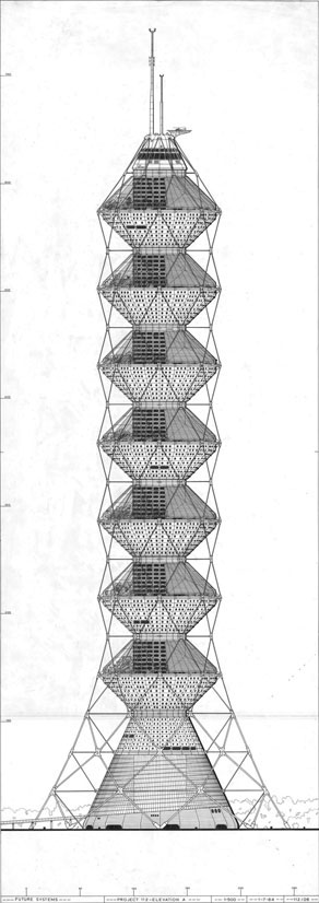
13.
Coexistence Tower by Future Systems. The compression core and the helical arrangement of tension members around the perimeter have functional similarities with the structure of tree trunks
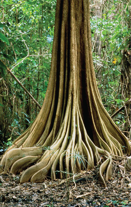
14. Trees growing in the shallow soils of rainforests have evolved buttress roots that resist overturning
The root forms of trees could also inspire new approaches to creating foundations for buildings. The formation of a wide, stiff base effectively moves the pivot point some distance from the trunk and, on the opposite side, a branching network of roots mobilises a vast amount of soil as ballast to resist overturning.23 In rainforests, where soils can be relatively shallow and therefore cannot provide the same resistance as those in temperate climates, trees have evolved pronounced buttresses (fig. 14) which actually work in tension to prevent overturning.24
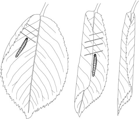
15.
The leaf roller caterpillar manipulates flat leaves into tubular forms by attaching threads across the surface and then shortening the threads in a manner similar to a ratchet strap
Transformations of planar surfaces
One of the simplest ways to transform a planar surface into something that provides protection is to roll it. The leaf roller caterpillar (genus Aenea) wraps a leaf into a tube, secures it with silk, and thus makes a structure within which it carries out its metamorphosis (fig. 15). The caterpillar uses this tube structure for a week, but recent research shows that it is then used by other organisms, and plays a significant role in increasing the density and diversity of arthropods. Similar ingenuity is evident in PLY Architecture’s elegant pavilion in Matthaei Botanical Gardens, Michigan (figs 16 & 17). Sheets of laser-cut aluminium were rolled into cones and then assembled based on patterns of phyllotactic geometry.

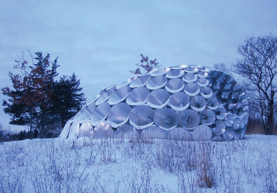
16–17. The Shadow Pavilion by PLY Architecture showing how a thin planar surface can be rolled into an element that generates a distinctive building form
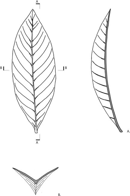
18. The Southern Magnolia leaf, stiffened through a combination of a curve and a fold
19.
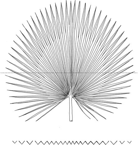
Fan palm leaves – an elegant example of how folds can transform a large, thin surface into a structure that can cantilever from a single point of support
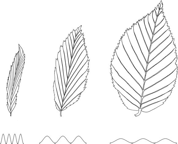
Plants have had to evolve ways to present large amounts of photosynthetic surface to absorb light. But a larger surface area needs more structuring, since growing bigger leaves by increasing their thickness has significant drawbacks. Curves and folds have evolved to create stiffer elements out of thin material. In the case of the Southern Magnolia, the fold occurs along the midrib and each half of the leaf is curved (fig. 18). Both the fold and the curve contribute to the leaf’s stiffness. In rainforest environments, daylight at forest-floor level is scarce and many plants have responded with large leaves folded into fan forms (fig. 19).
A stunning example of stiffening a thin surface can be found in the giant Amazon water lily (Victoria amazonica). Leaves of up to 3 m in diameter with smooth top surfaces are strengthened on their undersides by a radial, branching, network of ribs to an extent that can support the weight of a small child. The principle of using ribs to stiffen a thin surface may well have inspired engineers to design similarly efficient structures, and the concept could be applied widely.
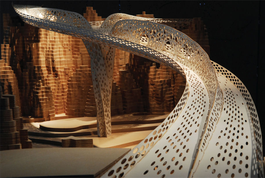
Architects Tonkin Liu, working with structural engineer Ed Clark at Arup, were inspired by the forms of marine molluscs and techniques from tailoring to develop a new form of construction derived from planar surfaces. They refer to this as a ‘shell-lace structure’ (figs 20 & 21). Just as in the molluscs, the structure derives its stiffness from the articulation of a thin surface: folds increase the effective structural depth, curves create added stiffness and twists provide a degree of triangulation. The end product is an extremely elegant structure, constructed with a minimum of materials, deriving its strength from its shape rather than its mass.

20. Diagrams by Tonkin Liu Architects showing how structural principles from shells were analysed
21.
The Shi Ling Bridge designed by Tonkin Liu Architects and structural engineer Ed Clark of Arup – an example of a ‘shell-lace structure’ that achieves efficiency of materials by exploiting vaulted, folded and twisted forms from shells
Shells and domes
Nature is an accomplished maker of shells and domes.25 One such builder whose specifications have been thoroughly scrutinised is the abalone (fig. 22). It has evolved a shell that electron microscopy reveals to be made of polygonal plates of calcium carbonate, bonded together with a flexible polymer mortar. The result is a material 3,000 times tougher than the chalk that makes up 95 per cent of its bulk. Whereas we tend to make homogenous materials through which a crack, once started, readily propagates, nature has evolved a matrix of hard platelets with phenomenal resistance to cracking. Each platelet creates a point at which a crack stops and must then start afresh on a new platelet if it is to continue through the material. A degree of flexibility in the polymer helps to spread concentrated loads over a larger area of shell.
22.
Shells may be one of the earliest sources of biomimicry, but now designers can benefit from the scientific knowledge that reveals how their microstructure contributes to their phenomenal toughness
23.
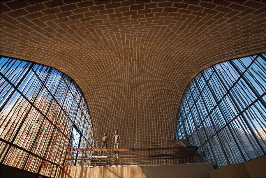
Mapungubwe Interpretation Centre designed by Peter Rich Architects using Guastavino vaulting – similar to an abalone shell and made with basic materials, such as sun-baked earth tiles
There is a vernacular method of construction called Guastavino vaulting (fig. 23) that has interesting parallels with the abalone and recently experienced a return to favour. This technique, named after the Valencian architect and builder Rafael Guastavino (1842–1908), involves, at its simplest, building a lower layer of terracotta tiles out from a circular concrete ring beam. This can be achieved without formwork as a plaster of Paris mortar is used, from which the tiles absorb moisture rapidly enough to form a good bond after half a minute. A second layer of tiles laid at a diagonal is applied on top with a stronger cement mortar, and then a third layer at the opposite diagonal. The result is an extremely strong shell structure that can span large distances and can be worked into a rich variety of forms. While this form of construction predates our current understanding of the detailed structure of the abalone, this does not stop us developing the idea further with biological inspiration. Is the origin biomimetic in the sense in which we use it now? This is an interesting question, as some vernacular architectural solutions could be adopted as genuinely biomimetic, allowing biomimicry to demonstrate its range of application from lowtech to cutting-edge contemporary technologies. Taking inspiration from the abalone’s functional properties, we could potentially use a flexible mortar to increase a structure’s crack resistance and spanning capabilities. We could also learn from molluscs to form corrugations and push spanning distances even further while using minimal quantities of material. In countries where earth tiles baked in the sun are commonly used, this approach offers huge potential to maximise the effectiveness of local materials and local labour to shape expressive and efficient structures.
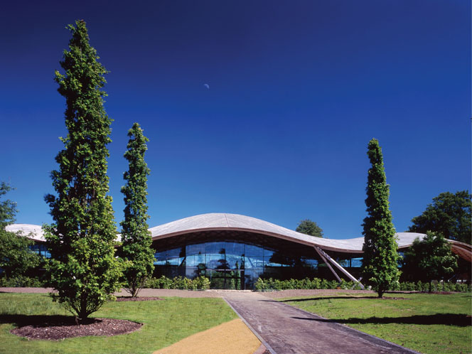
24. The Savill Building by Glenn Howells Architects. By using small sections of timber in a highly efficient form, gridshells can achieve factor-15 savings in resource use
Timber gridshells (fig. 24) could be considered transformations of planar surfaces; indeed, they are often built by starting with a flat grid and then distorting it into shape. However, the structural aim is not to form a stiffened plane but to get a series of linear elements – usually wood – to act together as a shell. Domes and shells were almost undoubtedly first inspired by studying natural examples. Some gridshells have achieved factor-15 savings in resource use: the Weald and Downland Gridshell by Ted Cullinan Architects with Buro Happold and Green Oak Carpentry weighed only 6 tonnes, compared to an estimated 100 tonnes for a traditional barn of equivalent size. The elegance of gridshells shows what can be achieved by using ingenuity rather than brute force.26
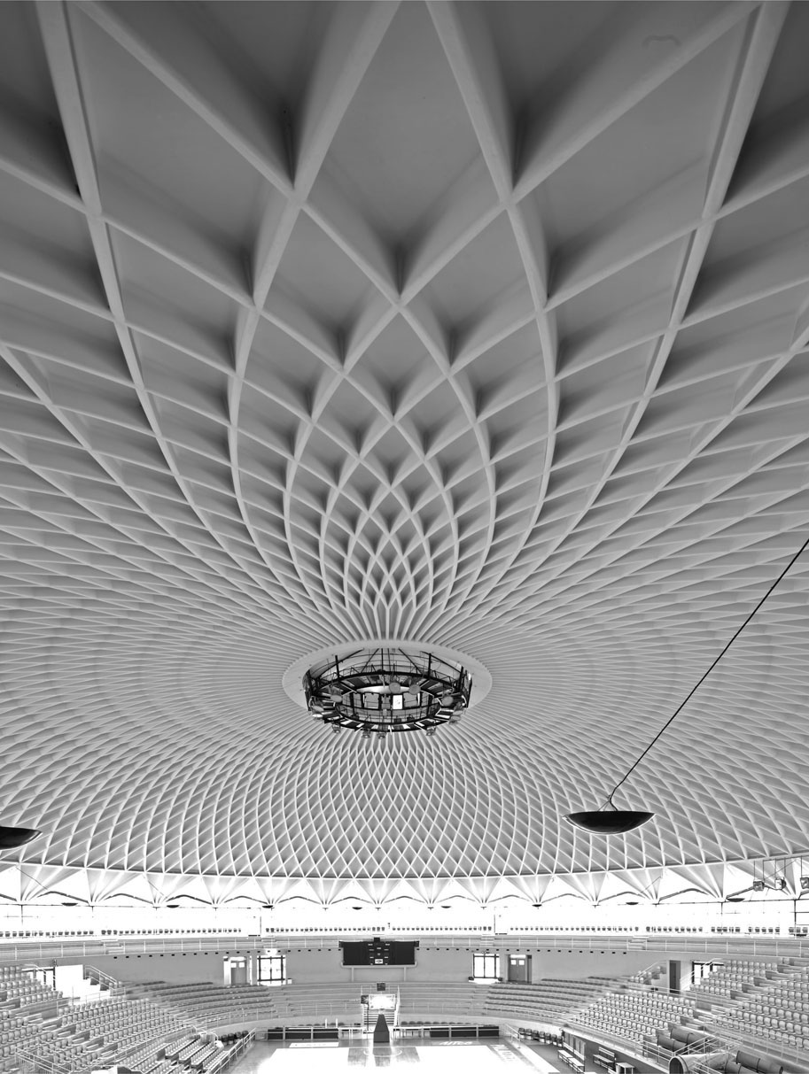
25. The engineering genius Pier Luigi Nervi frequently used examples from nature to inspire more efficient structures, as in this example of the Palazzetto dello Sport, which has a striking resemblance to the leaves of the giant Amazon water lily. In both cases downstand ribs are used to stiffen a thin surface
As Mario Salvadori has observed, domes could be regarded as a continuous series of arches arranged in a circle and joined monolithically.27 The engineering advantages become clear when one looks at the ratio of thickness to radius. For an arch, this ratio is typically between 1:20 and 1:30, whereas for a dome it is between 1:200 and 1:300. Little wonder, then, that this form of construction can be seen in biological examples as diverse as micro-organisms, seed pods, carapaces and skulls.
As we discussed with Guastavino vaulting, there is often potential to combine a number of biologically inspired approaches on a single project. The brilliant structural engineer Pier Luigi Nervi closely studied structures in biology and explored strategies to develop shells towards even greater efficiency. In the Palazzetto dello Sport (fig. 25), completed in 1957, he employed the principle of using ribs to give effective structural depth to a thin planar surface, combined with the benefits of dome/shell behaviour. In cooperation, radial bifurcating ribs reduce the distance over which the outer surface must span, while the outer surface in turn connects all the ribs together, so loads are more evenly distributed.
A challenge for architects and engineers in trying to emulate natural forms has been in achieving efficiency through complexity of form without adding excessive cost. While structures in nature are assembled molecule by molecule, human artefacts are constrained by the practical and economic limitations of our construction technology. For Nervi, the miracle material that allowed him to achieve his aims was reinforced concrete, about which he said, ‘The very fact of not having at its origin a form of its own … permits it to adapt itself to any form and to constitute resisting organisms’.28 He viewed reinforced concrete as ‘a living creature which can adapt itself to any form, need or stress’,29 and there is a sense in which his structures capture both muscular and skeletal qualities. Reinforced concrete was first used in a building structure in 1853, and by Nervi’s time its performance was better understood. His mastery of the material is such that, in many of his designs, we see the forces that are resolved made manifest in the forms of the structure. For example, the ribs and downstand beams in his Gatti Wool Factory (1953) precisely follow the lines of principal stresses (fig. 26). This suggests that when we consider biomimetic structural solutions, at the same moment we should be exploiting the performance of materials and seeking biomimetic uses or alternatives. Evolving the structural and materials solutions together is a hallmark of how nature operates, and a process that is also achievable in human design.
26. Structural layout for Nervi’s Gatti Wool Factory in which the alignment of the beams follows the lines of principal stresses
Many of Nervi’s projects were won through competitions. The secret to his success was his frequent ability to produce, simultaneously, formally compelling and also extremely cost-effective schemes. In a satisfying parallel with the refining process of evolution, his combination of ingenuity and biomimicry led to a remarkable efficiency of resources.
Skeletons
27.
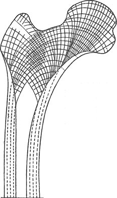
Diagram showing the lines of stress passing through a bone
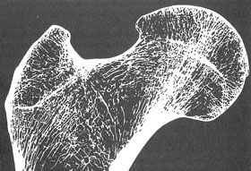
28.
X-ray through a bone showing the arrangement of bony trabeculae
Whereas bamboo is a relatively pure embodiment of tubular structural engineering, bones are more complex. Bones frequently reveal ways in which asymmetrical forces are resolved. Figure 27 shows the lines of stress through a femur, and figure 28 shows an X-ray image of the same bone. What we see is a precise match between the density of bone filaments and the concentration of stresses; where there is high stress, there is a proliferation of material and elsewhere there is a void. As biological mathematician D’Arcy Wentworth Thompson’s seminal 1917 book On Growth and Form30 documented, the vulture’s metacarpal (fig. 29) is identical to a Warren truss. The vulture is an extreme case, where intense selective pressure to achieve high strength with minimal weight yields impressive results.
Birds in general have evolved in response to intense selective pressure on weight, with different species showing various expressions of the ‘materials are expensive and shape is cheap’ maxim. Avian skulls (fig. 30), such as those of crows and magpies, are little short of engineering miracles. The effective thickness of the skull is increased while weight is decreased. The structure is similar to a space-frame in which two layers of structural members are connected with struts and ties. The bird skull goes one step further in forming a dome shape, with the associated efficiency benefits.
29.
As a result of intense selective pressure for lightness, some birds have evolved remarkably efficient structural forms, like this vulture’s metacarpal, which is effectively identical to a Warren truss
It’s an astounding combination of shell action with space-frame technology – and all in a humble magpie.
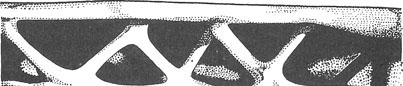
This principle was the inspiration for a canopy structure (fig. 31) designed by architect Andres Harris. The design resulted from a detailed understanding of the way in which bone tissue forms around pressurised cells, creating air voids between solid surfaces. The potential exists to construct the canopy in a way that is very similar to nature: using a web of inflated void formers, around which suitable materials could be cast.
Skeletons have been a source of inspiration for architects ever since Thompson demonstrated the parallels between structures such as the Forth Road Bridge and the form of dorsal vertebrae found in a horse.
Architect Santiago Calatrava is renowned for his love of skeletal structures; he created many of the most graceful bridges in the world. While his exuberance is enjoyable (fig. 32), there is a sense in which the biomorphic extravagance occasionally occludes a rational structural basis for the schemes. It could be argued that the beauty found in nature is derived from its economy, with the absence of the superfluous being part of the rigour that we perceive. This is a selective view because there

30. Section through the skull of a magpie showing thin domes of bone connected together with struts and ties
31.
Canopy structure designed by architect Andres Harris, using the same structural principles as those found in bird skulls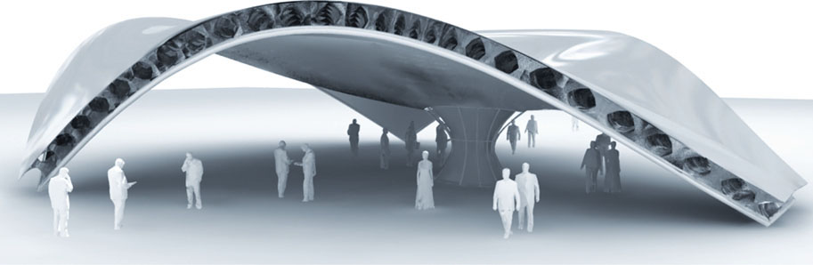
32.
Biomorphic exuberance in the Milwaukee Art Museum by Santiago Calatrava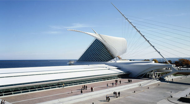
is plenty of extravagance to be found in biology, often associated with various forms of sexual display. But the interesting question to ask is: do the more decorative aspects add appropriate and necessary meaning to the building? If the aim is to produce beautiful, resource-efficient architecture that is enjoyable for people, then both biologically based design approaches can contribute. As I suggested in the Introduction, biomimetic design can deliver important innovation and biomorphic design can convey meaning.
33.
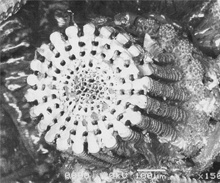
Diagram showing the structure of a sea urchin skeleton composed of interlocking plates made from calcite crystals
The sea urchin has inspired both simple biomorphic and thoroughgoing biomimetic architecture. The urchin skeleton (called a ‘test’) is made of interlocking plates (called ‘ossicles’) (fig. 33), each of which has the structure of a single calcite crystal.31 If the calcite were solid, it would be heavy, but the ossicles have a sponge-like structure (fig. 34) that is porous, lightweight and stiff due to its increased effective thickness.32 Sea urchin skeletons provided a visual reference for the Doughnut House by Future Systems (fig. 35), although the structure, at a functional level, had very little in common with that of the marine organism. A building that has deliberately come much closer to the structure of a sea urchin is the Landesgartenschau Exhibition Hall at the University of Stuttgart, Germany, where some of the most interesting and thorough research into biomimetic architecture is currently underway (fig. 36). The project was the result of a collaboration between the Institute for Computational Design (ICD, Prof. Menges (PI)), the Institute of Building Structures & Structural Design (ITKE, Prof. Knippers) and the Institute of Engineering Geodesy (IIGS, Prof. Schwieger). Sea urchin ossicles, and the way they interlock, were a source of inspiration for the building. It is made out of 50 mm thick plywood panels, connected with precise finger joints. Menges observed that ‘in comparison to man-made constructions, natural biological constructions exhibit a significantly higher degree of geometric complexity’.33 Computational design was essential to resolve this complexity in finding the optimum form. Each panel was then robotically prefabricated. The structure covers an area of 250 m2 and, in relative terms, is thinner than eggshell.
34.
Close-up photograph of a sea urchin skeleton showing its porous and lightweight structure
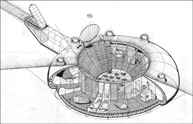
35. The Doughnut House by Future Systems – biomorphic rather than biomimetic

36.
Landesgartenschau Exhibition Hall at the University of Stuttgart – made from interlocking plywood panels based on the structure of a sea urchin skeleton
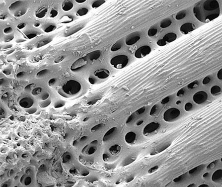
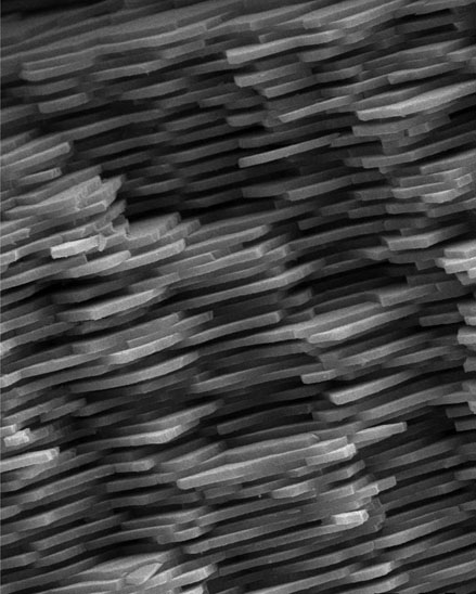
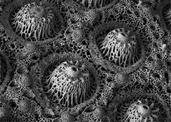
37–38. Close-up photographs showing the remarkable structure of sea urchin spines
Another noteworthy aspect of sea urchins is the structure of their spines (figs 37 & 38). These provide protection as well as locomotion and sensing. As protection, considerable strength is required to resist impact onto the ends of the spines – or ‘axial loading’ as an engineer would describe it. If the spines were monolithic, they would be very brittle. Instead, they have evolved in a porous form that blends calcite with proteins. The composite effect of these two materials is enhanced strength and flexibility. Are there applications in architecture that require high resistance to axial loading as well as flexibility? The sea urchin spine is a solution waiting for the right design opportunity.
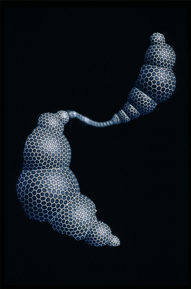
If Buckminster Fuller had ever designed a fish, one wonders if it might have looked something like the boxfish (perhaps Lactoria cornuta or Acanthostracion polygonius) (fig. 39). Their carapace is a remarkable geometrical composition of mainly hexagonal and pentagonal plates or ‘scutes’.34 Each of these has a tough mineralised collagen outer layer with a raised pattern of reinforcing struts and a softer, un-mineralised collagen layer underneath.35 The struts serve to distribute piercing impacts over a wider area (fig. 40). Finely interlocking seams unify the plates into an extremely strong skeleton – it is tempting to refer to it as an exoskeleton but it is actually an endoskeleton because it lies under a layer of skin. Some fish evolved faster swimming to avoid predation; boxfish developed a formidable defensive structure (and some toxicity for good measure). Further protection comes from two pairs of horns – one pair at the front and one at the rear – which would make for uncomfortable swallowing by a predator. The horns have an intriguing structure of their own – an intricate hierarchy of ridges and ribs to provide high strength. While buildings in the twenty-first century generally don’t have to be designed to resist attack, the boxfish carapace could still provide clues for how to stiffen thin materials into a robust enclosure using a minimum of resources.
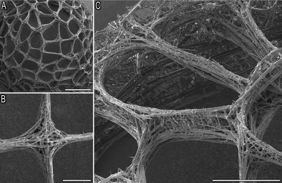
Just as twentieth-century anthropologists were compelled to revise the widely held racist notion of ‘primitive’ societies, there are certain biological organisms that should encourage us to abandon the idea of single- or multi-celled life forms being in some way ‘lower’ than others. One such example is the Venus’ flower basket glass sponge (Euplectella aspergillum) (fig. 41), which we will revisit in the chapters on materials and light.36 The structure of this marine organism is a complex assembly of spicules (four-pointed star-shaped elements made from silica) forming a tapered lattice tube (fig. 42).37 This square grid is stiffened with diagonal bracing on alternate cells like a chequerboard, so that every node is braced and open cells allow for filter feeding. The scientists studying this organism have observed that it ‘shares features with the theoretical design criteria for optimized material usage
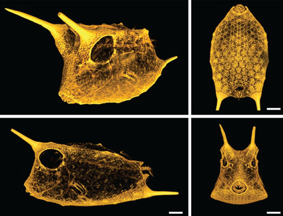
39. The carapace of the boxfish Acanthostracion polygonius showing its amazingly geometric arrangement of scutes
40.
Diagram of the scutes that form the boxfish carapace showing the arrangement of reinforcing ribs
in similar two-dimensional structures subjected to shear stresses’.38 The number, and size, of spicules around the perimeter stays constant along most of the length (only increasing in the top few centimetres39), so tapering is achieved by variations in the overlap of the spicules. Should we actually build this way or should we use continuous members that follow the gridded and braced layout? Probably the latter, but we shouldn’t rule out the possibility of mass-producing identical elements, like the spicules, which can then be assembled into effective and beautiful structures. There are claims that Foster + Partners’ 30 St Mary Axe (‘The Gherkin’) was based on the glass sponge, but these are unfounded.40 So far, it seems that Euplectella’s lessons are yet to be turned into architecture.
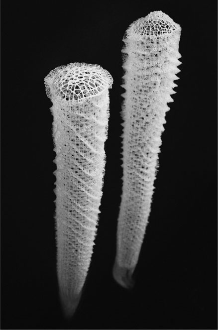
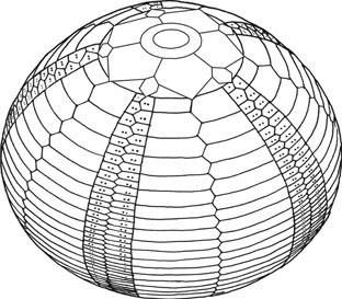
41. The glass sponge Euplectella aspergillum, made from silica at ambient temperature and pressure with five or more levels of hierarchy
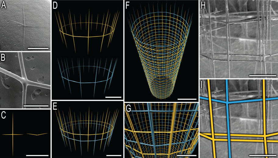
42.
Illustration showing how the glass sponge is assembled from a complex arrangement of intersecting, cross-shaped spicules
The glass sponge has a series of helical ridges and a rigid top ‘filter plate’ (fig. 43) that effectively stiffen the tube against the kind of failure we described earlier.41 The way that the sponge attaches to the sea bed is also intriguing. Materials scientist Professor Helga Lichtenegger has observed that anchoring can be achieved much more efficiently (in material terms) if the structure allows flexibility rather than rigidly resisting all lateral loads.42 Saplings demonstrate this phenomenon and so does the glass sponge – there is considerable pliancy at the base (the very point at which the highest stress would accumulate in a more rigid structural attachment). In the lower part of the sponge there is a longer and more fibrous type of spicule, approximately 200 of which extend down into the sediment of the sea floor to form a strong holdfast. Scanning electron microscopy has revealed these fibres to have smooth surfaces above sea bed level, barbed surfaces below and an anchor-shaped termination (fig. 44). Could this be a solution to anchoring offshore wind turbines in soft sediments? The industry recently took a lesson from razor clams, and perhaps the glass sponge is next?
43. Magnified image of the filter plate that stiffens the top of a glass sponge
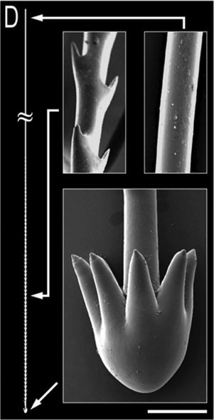
44.
Scanning electron microscope views of the fibrilar spicules that anchor the glass sponge in soft sediments. Above the sea bed the spicules are smooth, while below they are barbed and have a complex holdfast at the termination
Exoskeletons
External skeletons are one of the defining characteristics of the broad phylum of animals known as arthropods, which includes insects, arachnids, myriapods and crustaceans. Because of the diversity of insects on earth, arthropods account for more than 80 per cent of all animal species. Exoskeletons can also be found in microscopic diatoms and radiolaria. Tortoises show off by having both an exo- and an endoskeleton, which offers benefits of protection and mobility. These skeletons can teach us that, for some situations, a hybrid structure can provide additional flexibility.
The complex double-curved forms of arthropod exoskeletons can be a source of inspiration for architects and engineers fascinated by the efficient and expressive potential of monocoque construction. In the case of arthropods, their exoskeletons are made from three raw materials: mainly chitin (a polymer derived from glucose), modified and reinforced with proteins and biominerals.43 The fibres are arranged in layers with alternating directions in each, similar to plywood, delivering excellent material strength relative to its density and its fracture resistance. The ICD has built a pavilion based on an understanding of arthropod exoskeletons and translated into architectural form with great elan (and some clever robots). Since the form emerged primarily from a profound understanding of the material microstructure, this project is described in Chapter 2.
Woven, fastened and reciprocated structures
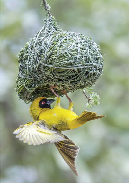
There are a number of examples of weaving in nature, mainly by birds. The appropriately named village weaver birds (fig. 45) (Ploceus cucullatus) employ as many as six different knots, including loops, half-hitches, hitches, bindings, slip knots and overhand knots, as well as weaving techniques. Another avian group worth getting acquainted with is the penduline tit family (Remizidae), which uses spiderweb, wool, animal hair and plant fibres to make a bag-like hanging nest, so tightly interwoven that even apes are not able to pull them apart. In parts of Eastern Europe they were used as children’s slippers.
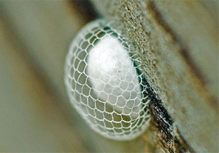
The long-tailed tit (Aegithalos caudatus) uses a combination of spider silk egg cocoons and fine-leaved mosses as a natural form of Velcro to hold its nest of twigs together.44 There are numerous examples of adhesives made from bodily secretions, including salivary mucus used by the chimney swift (Chaetura pelagica) to make its nest, and the little spiderhunter (Arachnothera longirostra) uses pop rivets made of silk to attach its nest to large leaves.45
45.
Nest structures built by the village weaver bird using as many as six different knots
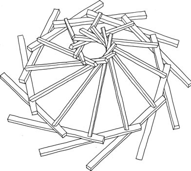
A reciprocal structure is one in which the overall span is longer than that of its individual members and each beam supports, and is supported by, the other beams in the structure. Many birds’ nests provide examples of this approach and it is generally employed when the gap to be spanned, say between the branches of a tree, exceeds the length of most of the available twigs. Short lengths of stick can be used to successively bridge the distance between two adjacent members that are at an angle to each other, eventually spanning the desired area as a base for the nest. While some such nests are relatively crude accumulations of sticks that rely on gravity and friction to hold them together, other birds use a range of fixing technologies to bind elements together.
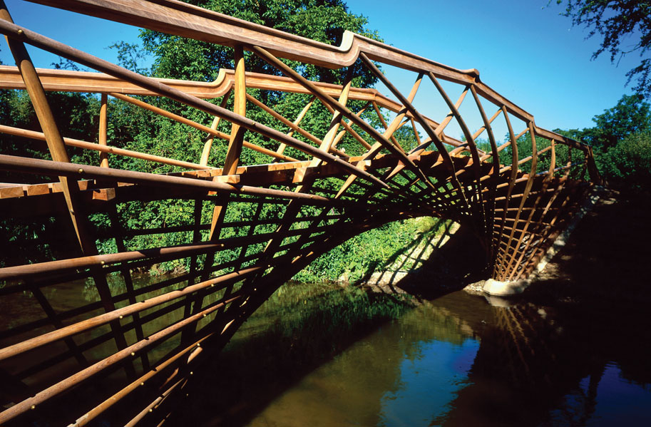
46. The Luxmore Bridge, Eton College, designed by Atelier One and Jamie McCulloch – a reciprocal structure in which a number of short structural elements are assembled to span further than their individual lengths
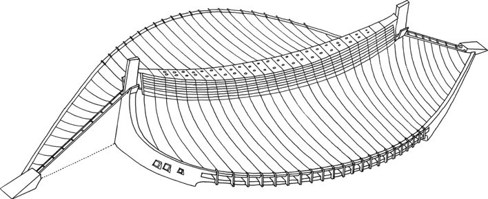
47.
The spiral reciprocal roof structure of the Seiwa Bunraku Puppet Theatre by Kazuhiro Ishi. Could we push the idea even further with lessons from birds’ nests?
There are certainly some elegant examples of man-made structures that use parallel techniques, such as Jamie McCulloch and Atelier One’s Luxmore Bridge (fig. 46) and the Seiwa Bunraku Puppet Theatre by Kazuhiro Ishii (fig. 47). More direct application of these construction methods from natural structures to human-made ones remains to be explored. Perhaps the most relevant lesson to draw is that nature’s woven, fastened and reciprocated structures could provide further clues for how we can use relatively small structural members to create elegant spanning structures without the need for large primary beams or trusses.
Webs / tension structures
Webs built by spiders have inspired a number of modern architects and engineers. Their forms range from the commonplace webs created by household spiders to the remarkably architectural tension structures of the grass spider (genus Agelenopsis) and the bizarre constructions of the bowl and doily spider (Frontinella communis) and the female bauble spider (Achaearanea globispira) (figs 48–50).

48.
Web made by the grass spider – a tension surface spread over grass ‘masts’
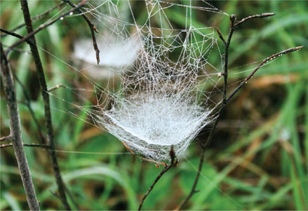
49. The bowl and doily spider’s dining arrangements
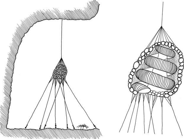
50.
House of the female bauble spider, apparently under the influence of Bruce Goff
Arguably, there is no greater champion of tension structures than the German architect and engineer Frei Otto (1925–2015). He pioneered cable-net buildings (fig. 51) and, through the Institute for Lightweight Structures that he established, published 32 volumes on structural design principles from nature.46 Comparing spider webs with cable-net structures, which are apparently very similar, reveals the gap that exists between biological manufacturing and our engineering: the relatively large sizing of the cables and the very visible connections being obvious differences. However, this is a gap that is narrowing all the time and, as we develop more sophisticated materials manufacturing and adaptive structures (see the ‘Integrated approaches’ section at the end of this chapter), we should be able to get closer to the elegant arachnid exemplars.

51. The West German Pavilion at Expo 1967, Montreal by Frei Otto – perhaps the closest we have come to the elegance of spiders’ webs
52.
Tokyo Olympic Gymnasium by Kenzo Tange – a distinctive form created with just two masts and all the remaining primary structural elements being tension cables
The most common form of tension structure is a cable net, which generally involves a series of guyed masts from which the web is suspended. Although it uses more substantial vertical elements than the tent-type schemes, Kenzo Tange’s brilliant Olympic Gymnasium in Tokyo is essentially the same (fig. 52). The Grimshaw team, for the proposed third climatic enclosure at the Eden Project, pursued a different approach. The imperative design requirement for this enclosure was for it to achieve the highest possible light levels. This led the team to explore an approach that placed the heavier compression members around the perimeter of the building, while over the growing area the most minimal arrangement of tension members would be stretched. The Dry Tropics Biome (fig. 53) used a distorted lattice ring-beam to form an anticlastic surface, such that at any point on the surface the cables, and the membrane that they support, would be tensioned in two directions for maximum resistance to wind loading.

53. The Eden Project Dry Tropics Biome by Grimshaw. The scheme aimed to maximise light levels inside by using a ring beam to stretch a minimal web of cables over the growing area
Pneumatic structures
A leaf, generally speaking, has very little woody tissue in it and relies instead for its stiffness on pressurised cell walls. Plants use energy to accumulate sugars in their cells, which promotes the in-flow of water and consequently internal pressure. The force of all the cells pressing against each other is what keeps the leaf rigid and explains why plants wilt when short of water. The effect is similar to a fully inflated lilo that is strong enough to stand upright or span as a cantilever. Scaling this idea up to suit a building would be difficult because the weight of water would become unmanageable. Fortunately, very similar effects can be achieved with membranes pressurised by air.
As architect Judit Kimpian has described in her dissertation ‘Pneumatrix – The Architecture of Pneumatic Structures in the Digital World’, air-supported constructions have had a somewhat chequered history. After considerable advances during the First and Second World Wars, there followed a wave of enthusiasm for pneumatics, culminating in a proliferation of inflatable pavilions at the 1970 Osaka Expo. Unfortunately, the popularity was short-lived as a combination of technical problems, poor workmanship and inadequate design tools led to the technology developing a tarnished image. In spite of all these shortcomings, pneumatic structures have an enduring fascination for biomimics, neatly captured by Reyner Banham’s assertion that ‘inflatables are alive in ways unknown to other building materials’.47 The first air-filled objects were quite likely to have been inspired by examples in nature, such as swim bladders in fish. Stephen Vogel explains the basic principle of pressurised structures in Cats’ Paws and Catapults as follows:
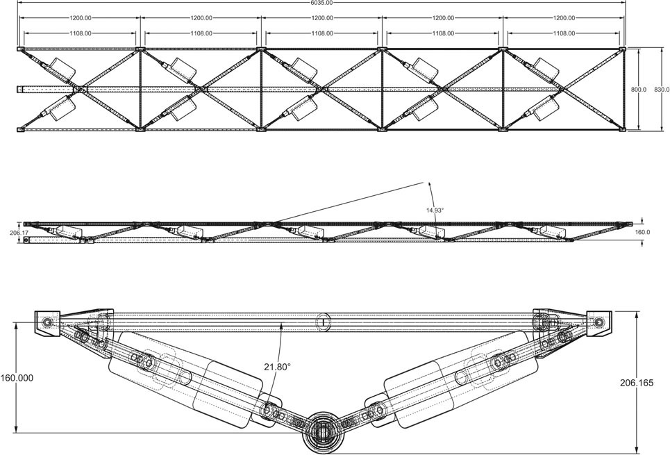
This is the basis of much work by the Swiss–Italian engineering firm Airlight Structures, who have developed air beams with impressive spanning capabilities (fig. 54). The beams are reinforced with a steel compression plate on the top and cable-tension members that run symmetrically from the ends of the plate, around each side of the air beam to the middle of the lower face and then up to the far ends of the plate. The inflated tube both stabilises the compression plate to minimise buckling and creates the structural depth to make it a spanning member. It is exactly equivalent to a conventional steel truss but neatly avoids the requirement for a substantial top compression member and solid struts. The hard work is done by air at modest pressure. Doubtlessly there will be scaling limits to the application of this technology but, for the versions that have been tested, it demonstrates a supremely elegant solution that uses a fraction of the materials to achieve the same result. The entry for the Douglas River Bridge (fig. 55) competition by Exploration with Airlight Structures shows the technology being used to create an ultra-lightweight span as a link between two areas of valuable biodiversity.
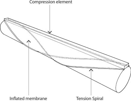
54.
A pneumatic beam by Airlight Structures which uses an inflated tube to create structural depth and to stabilise the top compression member
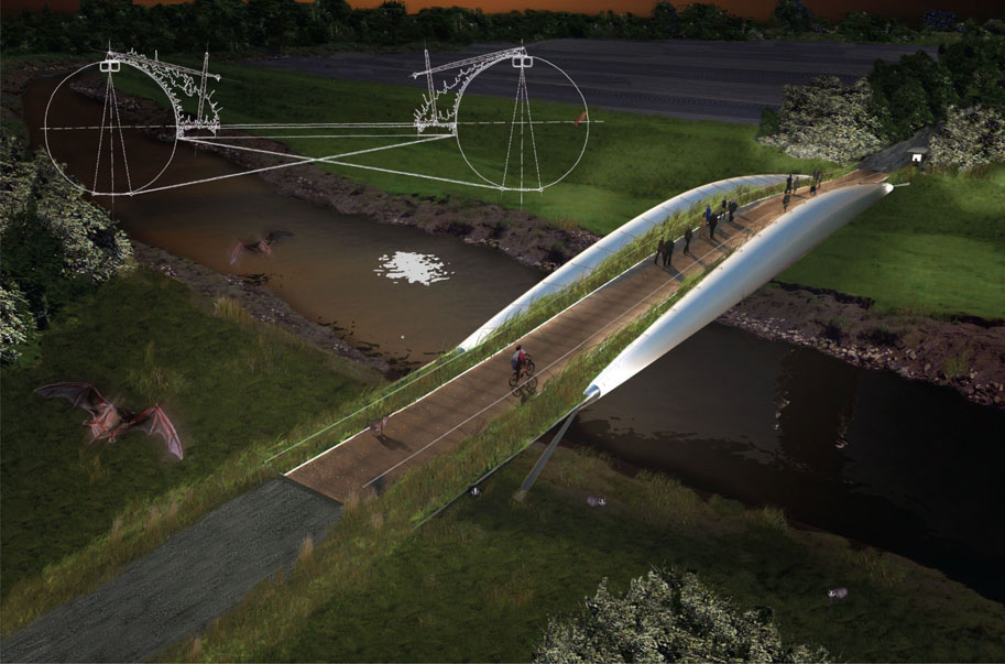
55.
The Douglas River Bridge by Exploration – using air structurally to create a lightweight crossing

56. Plan and section of the Inflatable Auditorium by Judit Kimpian – ‘bringing the building fabric “alive” with asymmetrically curved spaces, transient volumes and dynamic structures’
If it were to be built, Judit Kimpian’s Inflatable Auditorium would be a tour de force of pneumatic architecture (fig. 56). In many ways, a temporary auditorium is the perfect brief for pneumatic technology. In theatre design there is a continual quest for spaces that challenge and inspire the artists to create ever more adventurous works. In the Inflatable Auditorium, the focus was on ‘increasing the drama and suspense of a touring event by bringing the building fabric “alive” with … asymmetrically curved spaces, transient volumes and dynamic structures’.49
The design developed as a series of wide, inflated arch forms that avoided the need for any vertical supports. The arches connect together to form a stable, although not rigid, structure. Inflatables’ strength lies in their ability to transmit loading through deflection – something that characterises many natural structures and provides a stark contrast with the rigidity of much twentieth-century engineering. In nature, strength has evolved not by forming completely rigid structures but by accommodating movement.
The arches of the Inflatable Auditorium can be moved and their shape modified with pneumatic ‘muscles’. The building thus becomes a dramatic spectacle in itself and broadens the range of events that can be accommodated. While theatres have often been described with mechanistic language, Kimpian shows the potential for a theatre to be a quasi-living organism that can adapt to a wide range of functions.
Kimpian’s work suggests that, with the development of computer software that can accurately model and calculate inflated elements, pneumatic architectural technology has now come of age. Necessary material advances are also within reach, as biomimetic membranes are close to commercialisation. Soap bubbles and cell membranes are able to adapt to minute changes in strain along their surfaces whereas, to date, the membranes that we manufacture are only able to adapt to a very crude extent – by elasticity and local depressurisation. New ‘smart’ membranes are capable of real controlled shape change and could transform the performance of pneumatic structures.
Kimpian believes that, with design advances in pneumatics, air has been redefined ‘not only as a means of support for deployable structures, but as a smart building material which brings the dynamic transformation of space and volume within reach of mainstream architecture’, and that ‘inflatables can provide a means to realise some of the spatial possibilities emerging from a transient and perpetually evolving digital realm’.50 It is clear that the combination of pneumatics and biomimicry could deliver major breakthroughs: membranes that respond to the environment, with the flexibility to adapt to loads, forming enclosures with a fraction of the resources of conventional approaches.
Deployable structures
The whole notion of adaptive structures is appealing to a biomimic because it allows buildings to do what most living organisms do – modify their form or behaviour in response to changing conditions. Deployable structures can move, expand or contract by changing their geometric, material or mechanical properties.51 For biological organisms, rapid deployment offers numerous benefits: a leaf or flower can open to take advantage of particular weather conditions, insect wings can be folded and stowed after flight and long tongues can snatch prey before returning to coiled form. Moving limbs and skeletons are another ubiquitous example. We can aspire to equivalent advantage in our buildings with structures that expand to protect us from fierce sunlight, perhaps deploy focusing mirrors when we want more light or stretch out a membrane to harvest scarce rainfall. Roofs can open, walls can fold and whole buildings can move if there is a compelling case for doing so and the technology can catch up.
57. Hornbeam leaf – a simply folded surface that can be deployed by pushing along the centre line

58.
Hydraulic rams acting as muscles and steel sections as spinal vertebrae in Thomas Heatherwick’s ‘Rolling Bridge’
Examples of this can already be found in satellite solar arrays modelled on the simple unfolding pattern of the hornbeam leaf (fig. 57) and structures like Thomas Heatherwick’s ‘Rolling Bridge’ (fig. 58), which is effectively identical to a series of vertebrae with protruding spines that are connected by muscle-like hydraulic rams. Inspiration for pneumatic deployables could come from the pumping of seawater in the sea anemone.52
59. Convolvulus flower and a deployable pattern based on the same geometry. Some plants have evolved flower petals that can be rapidly deployed from a compact form to fully extended when the conditions are right. The deployable structure is designed by Guest & Pellegrino

60.
Umbrella for the forecourt of the Al Hussein Mosque, Cairo
Designer and pioneer of deployable structures Chuck Hoberman is now part of the Wyss Institute for Bio-inspired Engineering, so we can expect to see more examples of nature’s deployables being used to develop more effective solutions for humans. Conceivably, elegant examples like the convolvulus flower53 (fig. 59) or folding beetle wings could lead to sun-shading systems that can transform quickly from highly compact to fully deployed. Deployable biomimetic architecture has a humane quality of change which is deeply appealing, as well as promising refinements in form and energy efficiency (fig. 60).

61. An early computer model developed by the Grimshaw team when conceiving of the Eden Project as a string of bubbles to be set into the irregular site
Integrated approaches
The Eden Project, by Grimshaw, is another example of a scheme that drew on a range of solutions from biology – from the initial site selection and analysis through to the strategic form generation and the detail resolution.
The brief called for the world’s biggest greenhouse. The site was a deep, unstable china clay pit that was still being quarried. How were the team to design the building when there was no certainty about the ultimate shape of the site? Biomimicry was used throughout the design process to solve some of these seemingly intractable problems. A solar analysis first established the most beneficial parts of the site to inhabit: the south-facing quarry walls, which could absorb the sun’s heat during the day and then radiate that heat into the greenhouse – substantially reducing the number of days when additional heat input would be required. The irregularity of the topography, combined with the uncertainty over the final ground levels made conventional, rectilinear solutions all but impossible. The master-stroke came from team member David Kirkland, who proposed a radical solution inspired by soap bubbles (fig. 61). The idea was to create a string of bubbles, the diameters of which could be varied to provide the right growing heights in the different parts of the building, and to connect these along a necklace line that could be arranged to suit the approximate topography. The team explored different iterations of this bubble necklace and set them into 3D terrain models of the site. By cutting away everything that was below ground, the team arrived at the first images that resembled the final scheme (fig. 62).
The next challenge was to strive for the lightest possible structure. Studying a whole series of natural examples – from carbon molecules and radiolaria through to pollen grains (figs 63–66) – revealed that the most efficient way of structuring a spherical form is with a geodesic arrangement of pentagons and hexagons. Richard Buckminster Fuller pioneered the technology and even has a form of carbon molecule (the ‘Buckminster Fullerene’) named after him. The design started with conservative structural assumptions and then refined these using scale models in a wind tunnel to establish the wind loading. The most significant move in this process was in trying
62. Computer-generated image showing the sections of geodesic structure of the bubbles that protruded above the ground
to maximise the size of the hexagons so that light penetration could be increased. Glass would have been a serious constraint, both in terms of its unit sizes and weight, so the team explored a material that had, at the time, only been used at a much smaller scale. The team were aware that many efficient solutions in biology, from cell membranes to spiders’ webs, use pliable materials in tension rather than rigid materials in compression or bending. Ethylene tetrafluoroethylene (ETFE) is a high-strength polymer that can be formed into an ultra-lightweight cladding element by welding the edges of three layers together and then inflating it for stiffness.54 This represents another connection with Buckminster Fuller in that one of his students (and later a colleague), Jay Baldwin, invented the ‘pillow dome’ – a geodesic dome enclosed with inflated pillows, initially made from laminated vinyl and subsequently from ETFE. The great advantage of ETFE was that it was 1 per cent of the weight of glass (a factor-100 saving) and could be made in much larger ‘pillows’ than the biggest available sheets of safety glass. Thorough material testing allowed the design of the enclosure to be tuned to the specific conditions of the site.
63. Protective enclosure formed by the Sisyridae sponge-fly
64. A carbon molecule known as a Buckminster Fullerene
65. Radiolarian structure
66.
Pollen grain showing a geodesic structure
A positive cycle of design occurred in which one breakthrough facilitated another: larger pillows meant there was less steel, which in turn admitted more sunlight and reduced the amount of heat that would be needed in winter. Less steel also resulted in substantial savings in substructure. The result was a scheme that used a fraction of the resources of a conventional approach and cost a third of the normal rate for a glasshouse. The weight of the superstructure for the Humid Tropics Biome (fig. 67) is less than the weight of the air inside. If the team were to tackle the same challenge again, with more advanced materials technology and learning further lessons from biology, it is likely that further radical increases in resource efficiency could be achieved. For instance, 3D printing will, in time, allow steel tubes to be manufactured in a way that is closer to a biological approach – putting the material exactly where it needs to be according to stress concentration, rather than having a uniform diameter and wall thickness.
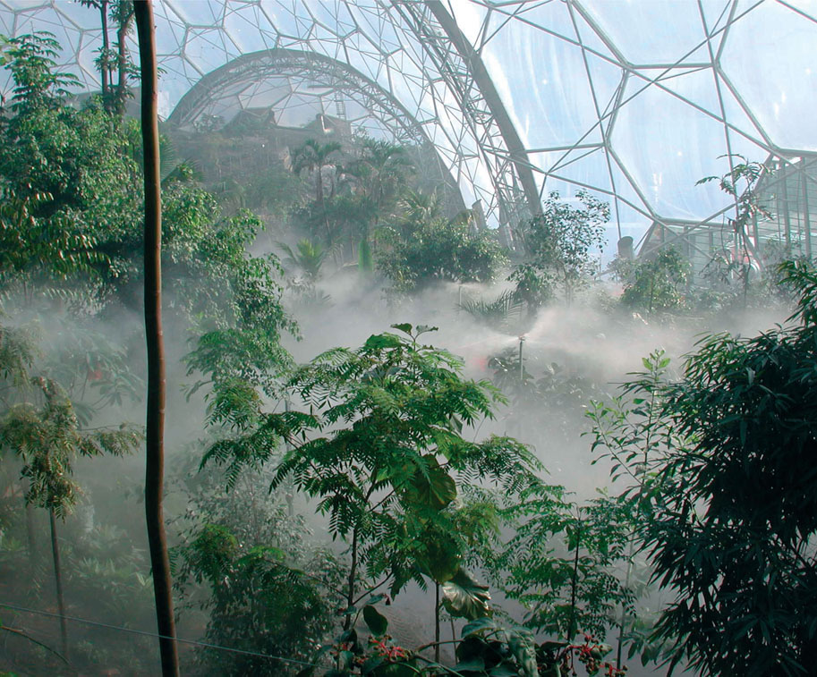
67. Interior of the Humid Tropics Biome
In contrast to many of the historical precedents that were studied, the biomimetic approach resulted in a much more sympathetic relationship with the landscape. Examples such as the Palm House at Kew – a highly symmetrical building on a flattened site – can be read as an expression of the view of nature that prevailed at the time, as something that could be dominated by humans. The Eden Project Biomes accommodate the existing form of the site with a minimum of excavation and suggest a more respectful reconciliation between humans and the natural world.
One of the key differences between biological structures and those made by humans is that, with the exception of deployables, ours don’t move. Most of the time we actively want to reduce the amount that things move, so that people feel safe and less inclined to revisit their lunch. This means that the amounts of material used in our structures can look extremely inelegant compared to the more pliant
68. Adaptive truss by University College London and Expedition Engineering. Radical resource efficiency was achieved by employing the same adaptive strategies as biological structures
forms found in nature. Recent research by University College London and Expedition Engineering has shown how this approach could be transformed with the development of their ‘adaptive truss’ (fig. 68).55 To explain the significance of this, it is worth clearly distinguishing between strength and stiffness. Strength is what is required to resist a load without breaking and stiffness is what is required to keep any deflections within acceptable limits. In many structures it is the required degree of deflection control that accounts for the vast majority of the structure. This adaptive truss is directly comparable to a skeleton controlled by muscles. Imagine you are holding a large tumbler at full stretch and someone fills it with water. As the weight increases, you would sense what is happening and compensate by making your muscles work harder. The adaptive truss works in exactly the same way: the bones are represented by compression members, the muscles by actuators and the nervous system by strain gauges, all controlled by a central computer. The amount of tension in the actuators can be increased or decreased according to the load. The sizing of the compression members can be close to the minimum required for strength. The result is an astonishing slenderness ratio (the depth of the structural element divided by its span) of 1/80 for a simply supported beam (1/12 – 1/20 is normal for a passive structure). It also means that an 80 per cent reduction in material can be achieved and whole-life energy savings of 76 per cent (taking into account both the embodied and the operational energy). Adaptive structures are at their best for structures that are only heavily loaded for a limited amount of time – perhaps a sports stadium, which may only accommodate a crowd for two hours a week, or a long-span roof, which is only subject to strong winds a few times each year.
The adaptive truss cleverly uses much less material yet still provides the required stiffness. There may be many other situations in which we can safely allow greater movement and, by doing so, save further resources.56 The leg bones of gazelles are an interesting biological example. Rather than being straight, which one might think offered the greatest strength, the bones have a gentle curve. This allows them to absorb much higher shock loading, such as might be experienced when making extreme jumps to escape from a predator. There are vernacular examples of this, such as crook-frame barns, for which trees were specifically grown in curved forms in order to create a degree of flexibility. Using large amounts of material to achieve rigidity could be described as a twentieth-century aberration and now we can deliver what biology and vernacular design both do: a more intelligent and resource-efficient form of responsiveness.
Conclusions
The axiom with which we started this chapter could now be extended to ‘more shape, less material, greater responsiveness’. At the start of the Industrial Revolution, resources were abundant and people were scarce; now we have the opposite situation. The case for approaches that use more human resources and fewer physical resources is even stronger. The biological paradigm translated into architecture means putting people at the centre: employing their ingenuity during design, involving them in the richly rewarding act of building57 and the enjoyment of beauty. Some of the biomimetic structures described – such as vaulting, weaving and reciprocating basic materials into elegant structures – would be perfectly suited to developing countries where resource pressures are most acutely felt. Lessons from vernacular structures could be reinterpreted to deliver both resource savings and a sense of cultural continuity.
We can use biomimicry to evolve towards more integrated design, sidestepping foundation–structure–cladding–finishes approaches. Many of the examples outlined above demonstrate the potential to achieve radical increases in resource efficiency by using biological structures as a model: manipulations of thin planar surfaces, Nervi’s ability to out-compete through lightness, domes and shells achieving factor-10 increases in efficiency and thin pressurised membranes taking this even further to achieve factor-100 increases in resource efficiency. With access to ever-improving scientific knowledge, designers will be able to draw on the many examples of ruthless refinement in nature, as well as the processes that led to that level of refinement, in order to create structures with beauty and efficiency. Concentrating our efforts on even just the easier and more accessible resource savings that biomimicry offers architecture, we can secure substantial wins.
This is of far more significance than passing technical interest. As described in the Introduction, we need to learn to do more with far less resource input if we are to address the combined pressures of a growing global population and resource shortages.
In the next chapter we will see some of the distinctions between our materials and nature’s and how we can benefit from approximating the molecular-level manufacturing that goes on in nature.