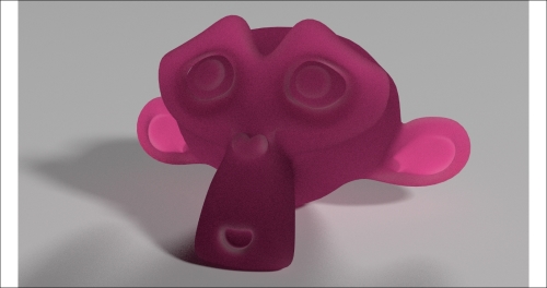
In this recipe, we will create a fake Subsurface Scattering node group that can be mixed with other nodes to add the fake scattering effect to a material. In this screenshot, you can see the effect of the Subsurface Scattering node alone on the Suzanne mesh:

The rendered result of the fake SSS node group assigned to Suzanne
In the following screenshot, you can see the effect of the node group added to the usual basic shader material:

Mixed with a Diffuse-Glossy shader
Again, we will use the colors of the previous recipes.
Start Blender and open the 9931OS_07_start.blend file.
- Go to the Render window, and in the Sampling subpanel, click on the Method to sample lights and materials button to switch from Path Tracing to Branched Path Tracing. Enable the Square Samples item and under AA Samples, set the Render value to
8. Finally, click on the Pattern button to select the Correlated Multi-Jitter option. - Save the file as
9931OS_07_SSS_ngroup.blend.
Now let's create the material using the following steps:
- Click on the New button in the Node Editor window toolbar or in the Material window under the main Properties panel. In the Node Editor window, delete the Diffuse BSDF shader node.
- Add a Light Path node (press Shift + A and navigate to Input | Light Path) and a Geometry node (press Shift + A and navigate to Input | Geometry).
- Add a Math node (press Shift + A and navigate to Converter | Math). Set Operation to Multiply and connect the Ray Length output of the Light Path node to the first Value input socket. Set the second Value input socket to
-1.500. - Press Shift + D to duplicate the Multiply-Math node, and set Operation to Power. Connect the Multiply-Math node output to the second Value input socket of the Power node. Set the first Value to
20.000. - Press Shift + D to duplicate the Power node, and set Operation to Add. Connect the Power node output to the second Value input socket of the Add-Math node, and the Is Camera Ray output of the Light Path node to the first Value input socket of the Add-Math node.
- Press Shift + D to duplicate the Add node. Set the Operation to Minimum. Connect the output of the Add node to the first Value input socket of the Minimum node, and set the second Value input socket to
1.000. - Press Shift + D to duplicate the Power node, and place it after the Minimum node. Connect the output of the Minimum node to the first Value input socket of the duplicated Power node.
- Add a Value node (press Shift + A and navigate to Input | Value), label it as
Contrast, and connect its output to the second Value input socket of the last Power-Math node. Set Value to1.200. - Press Shift + D to duplicate any of the Math nodes, set Operation to Subtract, and connect the Backfacing output of the Geometry node to its second Value input socket. Set the first Value input socket to
1.000. - Press Shift + D to duplicate the Subtract node, set Operation to Add, and paste it between the first Add and Minimum nodes. Connect the output of the Subtract node to the second Value input socket of the last Add node.
- Add a ColorRamp node (press Shift + A and navigate to Converter | ColorRamp) and connect the output of the last Power-Math node to its Fac input socket. Add a Translucent BSDF node (press Shift + A and navigate to Shader | Translucent BSDF) and connect the Color output of the ColorRamp node to its Color input socket.
- Set the ColorRamp node's Interpolation to B-Spline. Click on the Add button to add a new stop with Color values for R as
0.500, G as0.500, and B as0.500at the position of0.500. - Add a MixRGB node (press Shift + A and navigate to Color | MixRGB). Set Blend Type to Overlay and the Fac value to
1.000. Connect the Color output of the ColorRamp node to the Color1 input socket. Set Color2 values for R as0.500, G as0.054, and B as0.077. - Connect the Color output of the Overlay node to the Color input socket of the Translucent BSDF node. Connect the output of the Translucent BSDF node to the Surface input socket of the Material Output node as shown in the following screenshot:

The network to be grouped
- Now select all the nodes except the Value and Material Output nodes. Press Ctrl + G to create a Node Group.
- Rename the exposed input socket to the left of the node group as
Contrast, set the value on the group interface, and then delete the original Value node. - Click and drag the Color2 socket of the Overlay node to the empty socket on the Group Input node, and rename the exposed socket as
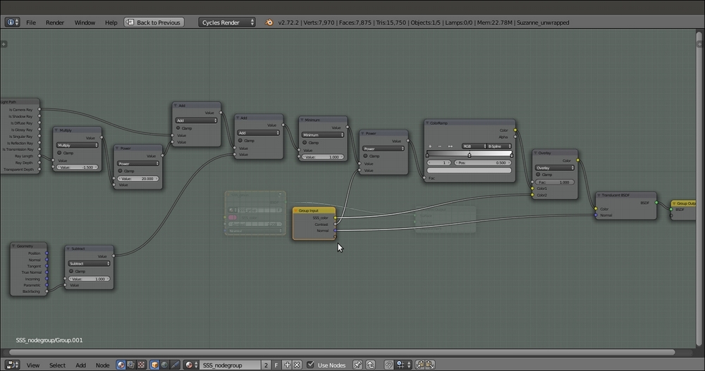
Subsurface Scattering_color. Then click and drag the Normal socket of the Translucent BSDF shader node to the empty socket as shown in the following screenshot:
The network inside the open-for-editing node group
- Press Tab to close the node group, and rename it
SSS_group.
So now, we have made the Subsurface Scattering node group, ready to be mixed with any surface material.
Let's now create a simple material to mix the node group using the following steps:
- Add a Mix Shader node, a Diffuse BSDF node, and a Glossy BSDF shader node (press Shift + A and navigate to Shader | ...). Connect the Diffuse BSDF node output to the first Shader input socket of the Mix Shader node and the Glossy BSDF shader output to the second Shader input socket.
- Connect the Mix Shader output to the Surface input socket of the Material Output node.
- Set the Color values of the Diffuse BSDF shader node for R to
0.031, G to0.800, and B to0.000. Set the Color values of the Glossy BSDF node for R to0.646, G to0.800, and B to0.267. - Add a Voronoi Texture node (press Shift + A and navigate to Texture | Voronoi Texture) and a Bump node (press Shift + A and navigate to Vector | Bump). Connect the Fac output of the texture node to the Height input socket of the Bump node, and the Normal output of this node to the Normal input sockets of the Diffuse BSDF and Glossy BSDF shaders, and also of the
SSS_groupnode group. - Set the Bump node's Strength to
0.150and enable the Invert item. Set the Voronoi Texture node's Scale value to22.500. - Add a Fresnel node (press Shift + A and navigate to Input | Fresnel) and connect it to the Fac input socket of the Mix Shader node. Set the IOR value to
3.250.
Now let's simply add the Subsurface Scattering node group:
- Add an Add Shader node (press Shift + A and navigate to Shader | Add Shader) and paste it between the Mix Shader node and the Material Output node. Switch the connection from the first socket to the second socket (this is actually not required in this case because the shaders are added anyway).
- Connect the output of the
SSS_groupnode to the first socket of the Add Shader node as shown in the following screenshot:
The SSS node group added to the diffuse and glossy components of an average shader
The key of this material is obviously the Light Path node, with its several kinds of output. In this case, we are interested in two of them:
- The Ray Length and Is Camera Ray output of the Light Path node are added together. Ray Length defines the thickness of the mesh, and it's also clamped by the first Multiply node and the Power node. The Is Camera Ray output gets Cycles to render only those surface points that are directly hit by light rays emerging from the Camera. When added to each other, the two types of output produce a stencil effect, gray-scale values distributed according to the thickness of the mesh.
- Next, the Backfacing output of the Geometry node is added to take into consideration the color of the back mesh faces. All of this is multiplied by the second Power node for the Contrast value and further clamped by the ColorRamp node.
- At this point, the result is mixed with the Subsurface Scattering_color output by the Overlay node, and finally connected to the Color input socket of the Translucent BSDF shader, resulting in the semi-transparent-looking shader of the first image at the beginning of this recipe.
