
8 Drainage Systems, Sewage Treatment and Refuse Disposal

Drainage Systems – Combined and Separate Systems
The type of drainage system selected for a building will be determined by the local water authority’s established sewer arrangements. These will be installed with regard to foul water processing and the possibility of disposing of surface water via a sewer into a local watercourse or directly into a soakaway.
Combined system – this uses a single drain to convey both foul water from sanitary appliances and rainwater from roofs and other surfaces to a shared sewer. The system is economical to install, but the processing costs at the sewage treatment plant are high.
Separate system – this has foul water from the sanitary appliances conveyed in a foul water drain to a foul water sewer. The rainwater from roofs and other surfaces is conveyed in a surface water drain into a surface water sewer or a soakaway. This system is relatively expensive to install, particularly if the ground has poor drainage qualities and soakaways cannot be used. However, the benefit is reduced volume and treatment costs at the processing plant.

Key:
IC = Inspection chamber
WG = Waste gully
YG = Yard gully
RP = Rodding point
RWG = Rainwater gully
RG = Road gully
RWS = Rainwater shoe
S & VP = Soil and vent pipe (discharge stack)
Drainage Systems – Partially Separate System
Partially separate system – most of the rainwater is conveyed by the surface water drain into the surface water sewer. For convenience and to reduce site costs, the local water authority may permit an isolated rainwater inlet to be connected to the foul water drain. This is shown with the rainwater inlet at A connected to the foul water inspection chamber. Also, a rodding point is shown at B. These are often used at the head of a drain, as an alternative to a more costly inspection chamber.
A back inlet gully can be used for connecting a rainwater downpipe or a waste-pipe to a drain. The bend or trap provides a useful reservoir to trap leaves. When used with a foul water drain, the seal prevents air contamination. A yard gully is solely for collecting surface water and connecting this with a drain. It is similar to a road gully, but smaller. A rainwater shoe is only for connecting a rainwater pipe to a surface water drain. The soil and vent pipe or discharge stack is connected to the foul water drain with a rest bend at its base. This can be purpose made or produced with two 135° bends. It must have a centre-line radius of at least 200mm.
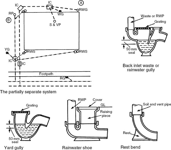
Rodding points or rodding eyes provide a simple and inexpensive means of access at the head of a drain or on shallow drain runs for rodding in the direction of flow. They eliminate isolated loads that manholes and inspection chambers can impose on the ground, thus reducing the possibility of uneven settlement. The system is also neater, with less surface interruptions. Prior to installation, it is essential to consult with the local authority to determine whether the system is acceptable and, if so, to determine the maximum depth of application and any other limitations on use. As rodding is only practical in one direction, an inspection chamber or manhole is usually required before connection to a sewer.

Refs. Building Regulations, Approved Documents H1: Foul water drainage and H3: Rainwater drainage.
BS EN 752: Drain and sewer systems outside buildings.
Connections between drains and sewers must be obliquely in the direction of flow. Drains may be connected independently to the public sewer so that each building owner is responsible for the maintenance of the drainage system for that building up to the property boundary. Thereafter, ownership and responsibility for the drain is with the water and sewerage authority. In situations where there would be long drain runs, it may be more economical to connect each drain to a shared sewer. This requires only one sewer connection for several buildings. Responsibility for maintenance of the shared sewer is the local water and sewerage authority’s.

Connection of a drain to the public sewer can be made with a manhole. If one of these is used at every connection, the road surface is unnecessarily disrupted. Therefore a saddle is preferred, but manhole access is still required at no more than 90m intervals. Saddles are bedded in cement mortar in a hole made in the top of the sewer.
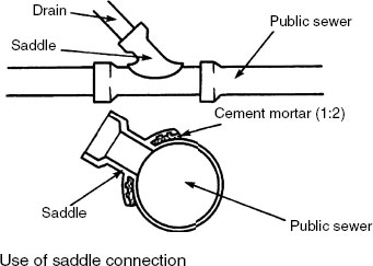
Note: The term lateral drain may be used to describe a shared drain or sewer.
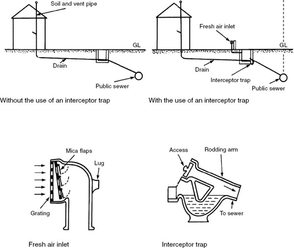
Venting of foul water drains is necessary to prevent a concentration of gases and to retain the air inside the drain at atmospheric pressure. This is essential to prevent the loss of trap water seals by siphonage or compression. The current practice of direct connection of the discharge stack and drain to the public sewer provides a simple means of ventilation through every stack. In older systems, generally pre-1950s, an interceptor trap with a 65mm water seal separates the drain from the sewer. The sewer is independently vented by infrequently spaced high-level vent stacks. Through ventilation of the drain is by fresh air inlet at the lowest means of access and the discharge stack. It may still be necessary to use this system where new buildings are constructed where it exists. It is also a useful means of controlling rodent penetration from the sewer.
To reduce installation costs and to eliminate roof penetration of ventilating stacks, discharge stacks can terminate inside a building. This is normally within the roof space, i.e. above the highest water level of an appliance connected to the stack, provided the top of the stack is fitted with an air admittance valve (AAV). An AAV prevents the emission of foul air, but admits air into the stack under conditions of reduced atmospheric pressure. AAVs are limited in use to dwellings of no more than three storeys, in up to four adjacent buildings. The fifth building must have a conventional vent stack to ventilate the sewer.

Unventilated Stacks – Ground Floor Only
Direct connection – a WC may discharge directly into a drain, without connection to a soil and ventilating stack. Application is limited to a maximum distance between the centre line of the WC trap outlet and the drain invert of 1·5m.
Stub stack – this is an extension of the above requirement and may apply to a group of sanitary fittings. In addition to the WC requirement, no branch pipes to other fittings may be higher than 2 m above a connection to a ventilated stack or the drain invert.
The maximum length of branch drain from a single appliance to a means of drain access is 6m. For a group of appliances, it is 12m.

Refs. Building Regulations, Approved Document H1, Section 1: Sanitary pipework.
BS EN 12056–2: Gravity drainage systems inside buildings.
Sanitary pipework, layout and calculation.
The bottom of a drain trench must be excavated to a gradient. This is achieved by setting up sight rails, suitably marked to show the centre of the drain. These are located above the trench and aligned to the gradient required. At least three sight rails should be used. A boning rod (rather like a long ‘T’ square) is sighted between the rails to establish the level and gradient of the trench bottom. Wooden pegs are driven into the trench bottom at about 1 m intervals. The required level is achieved by placing the bottom of the boning rod on each peg and checking top alignment with the sight rails. Pegs are adjusted accordingly and removed before laying the drains. For safe working in a trench, it is essential to provide temporary support to the excavation.

Drain access may be obtained through rodding points (page 316), shallow access chambers, inspection chambers and manholes. Pipe runs should be straight and access provided only where needed, i.e.:
at significant changes in direction
at significant changes in gradient
near to or at the head of a drain
where the drain changes in size
at junctions
on long, straight runs.
Maximum spacing (m) of access points based on Table 10 of Approved Document H1 to the Building Regulations:


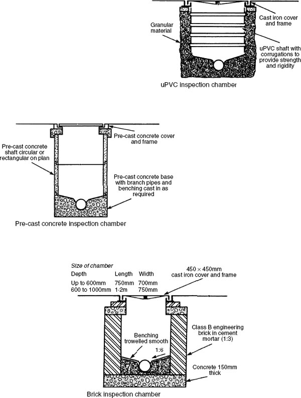
Shallow access chambers or access fittings are small compartments similar in size and concept to rodding points, but providing drain access in both directions and possibly into a branch. They are an inexpensive application for accessing shallow depths up to 600mm to invert. Within this classification manufacturers have created a variety of fittings to suit their drain products. The uPVC bowl variation shown combines the facility of an inspection chamber and a rodding point.

Note: Small lightweight cover plates should be secured with screws, to prevent unauthorised access, e.g. children.

Inspection chambers are larger than access chambers, having an open channel and space for several branches. They may be circular or rectangular on plan and preformed from uPVC, precast in concrete sections or traditionally constructed with dense bricks from a concrete base. The purpose of an inspection chamber is to provide surface access only, therefore the depth to invert level does not exceed 1m.
The term manhole is used generally to describe drain and sewer access. By comparison, manholes are large chambers with sufficient space for a person to gain access at drain level. Where the depth to invert exceeds 1m, step irons should be provided at 300mm vertical and horizontal spacing. A built-in ladder may be used for very deep chambers. Chambers in excess of 2·7m may have a reduced area of access known as a shaft (min. 900 × 840mm or 900mm diameter), otherwise the following applies:
Depth (m) |
Internal dimensions (mm) l × b |
Cover size |
|---|---|---|
<1·5 |
1200 × 750 or 1050diam. |
Min. dimension 600mm |
1·5–2·7 |
1200 × 750 or 1200diam. |
Min. dimension 600mm |
>2·7 |
1200 × 840 or 1200diam. |
Min. dimension 600 mm |
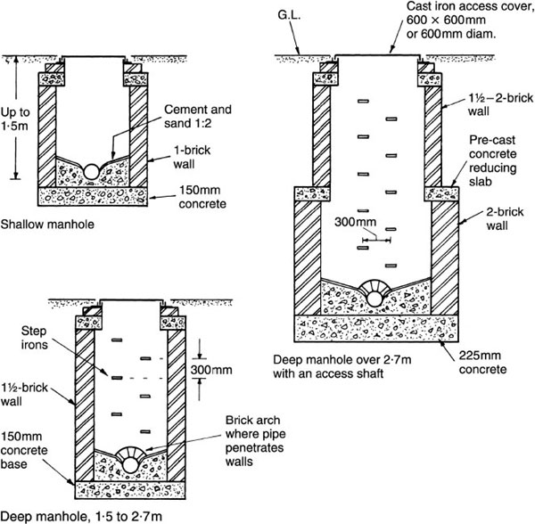
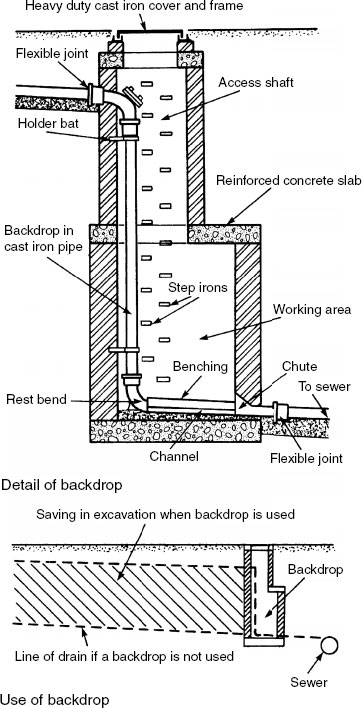
Where there is a significant difference in level between a drain and a private or public sewer, a backdrop may be used to reduce excavation costs. Backdrops have also been used on sloping sites to limit the drain gradient, as at one time it was thought necessary to regulate the velocity of flow. This is now considered unnecessary and the drain may be laid to the same slope as the ground surface. For use with cast iron and uPVC pipes up to 150mm bore, the backdrop may be secured inside the manhole. For other situations, the backdrop is located outside the manhole and surrounded with concrete.
The access shaft should be 900 × 840mm minimum and the working area in the shaft at least 1·2m × 840mm.
Drains must be laid with due regard for the subsoil condition and the imposed loading. The term bedding factor is applied to laying rigid drain-pipes. This describes the ratio of the pipe strength when bedded to the pipe test strength as given in the relevant British Standard.
Class A bedding gives a bedding factor of 2·6, which means that a rigid drain-pipe layed in this manner could support up to 2–6 times the quoted BS strength. This is due to the cradling effect of concrete, with a facility for movement at every pipe joint. This method may be used where extra pipe strength is required or great accuracy in pipe gradient is necessary. Class B bedding is more practical, considerably less expensive and quicker to use. This has a more than adequate bedding factor of 1–9. If used with plastic pipes, it is essential to bed and completely surround the pipe with granular material to prevent the pipe from distortion.

Approved Document H to the Building Regulations provides many methods which will support, protect and allow limited angular and lineal movement to flexibly jointed clay drain-pipes. Those shown below include three further classifications and corresponding bedding factors. Also shown is a suitable method of bedding flexible plastic pipes. In waterlogged trenches it may be necessary to temporarily fill plastic pipes with water to prevent them from floating upwards while laying. In all examples shown, space to the sides of pipes should be at least 150mm.

* Fields and gardens, min. 600mm Roads and drives, min. 900mm (max. 6m)
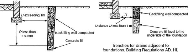
Drains Under or Near Buildings
Drain trenches should be avoided near to and lower than building foundations. If it is unavoidable and the trench is within 1 m of the building, the trench is filled with concrete to the lowest level of the building. If the trench distance exceeds 1m, concrete is filled to a point below the lowest level of the building equal to the trench distance less 150mm.
Drains under buildings should be avoided. Where it is impossible to do so, the pipe should be completely protected by concrete and integrated with the floor slab. If the pipe is more than 300mm below the floor slab, it is provided with a granular surround. Pipes penetrating a wall below ground should be installed with regard for building settlement. Access through a void or with flexible pipe joints each side of the wall are both acceptable.

Vitrified clayware – 100, 150, 200, 225, 250, and 300mm diameter nominal bore in 1.75m lengths (1.60m for 100mm nom. bore). Also produced in a range of sizes from 400 to 600mm diameter nominal bore for communal sewer pipes.
Ref. BS EN 295–1.
uPVC – standard outside diameters of 110 and 160mm corresponding with nominal bore diameters of 100 and 150mm in 3.00 and 6.00m lengths. Other nominal bore diameters are 200, 250 and 315mm.
Refs. BS 4660, BS EN 1401–1 and BS EN 13598–1.
Also produced in a structured or profiled twin wall format with a smooth bore and a ribbed external surface to provide for axial rigidity and radial strength.
Cast iron – available in standard nominal bore diameters of 100, 150 and 225mm. Larger nominal bore diameters are available in several sizes up to 600mm. Suitable for suspending under raised floors and in false ceilings, for bridge drainage and use in unstable ground and ground known to contain methane gas.
Refs. BS 437 and BS EN 877.
Concrete – sewer pipes in nominal bore diameters of 300, 375, 450, 525, 600 and 675mm. Above this, in a range of diameters up to 2.10m nominal bore. Standard lengths are 2.50m.
Refs. BS 5911–1 and BS EN 1916.
Asbestos cement – obsolete due to being a potential health hazard and superseded by lightweight uPVC. Used as drainage pipe material until the early 1970s, therefore it may be found when existing drainage systems are exposed. Where located, must only be handled by specialist contractors (see page 7).
Pitch fibre – also obsolete since the introduction of lightweight uPVC, but will be found in existing drainage systems particularly those installed between about 1950 and the late 1970s. Made from wood fibre impregnated with coal tar, pitch or bitumen. Design life is about 40 years, after which delamination may occur causing loss of strength and subsequent collapse.
Rigid jointing of clay drain-pipes is now rarely specified, as flexible joints have significant advantages:
They are quicker and simpler to make.
The pipeline can be tested immediately.
There is no delay in joint setting due to the weather.
They absorb ground movement and vibration without fracturing the pipe.
Existing clay drains will be found with cement and sand mortar joints between spigot and socket. Modern pipe manufacturers have produced their own variations on flexible jointing, most using plain-ended pipes with a polypropylene sleeve coupling containing a sealing ring. Cast iron pipes can have spigot and sockets cold caulked with lead wool. Alternatively, the pipe can be produced with plain ends and jointed by rubber sleeve and two bolted couplings. Spigot and socket uPVC pipes may be jointed by solvent cement or with a push-fit rubber ‘O’ ring seal. They may also have plain ends jointed with a uPVC sleeve coupling containing a sealing ring.

Anti-flood Devices – Interceptor Trap and Gully
Blockage in a public sewer or a period of prolonged heavy rainfall can cause surcharging and back flooding in drains. An anti-flooding facility must be installed to buildings on relatively low-lying sites, cellars, basements and where rainwater discharges directly into watercourses that may overflow. A risk assessment survey will determine whether a supplementary pump installation is required.
In situations where an interceptor trap is installed, an anti-flooding type should be specified in place of a standard interceptor. An antiflood gully is simpler and quite effective if regularly maintained to remove silt and other deposits.

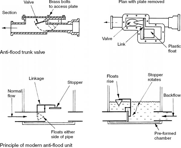
Anti-flooding Devices – Trunk Valve
Anti-flood valves are an alternative to anti-flood gullies. Located in the drain run, they require less maintenance and attention than floor- or ground-level gullies. Anti-flood trunk valves have been in use for a considerable time. These are contained within a purpose- built access chamber or manhole close to the sewer or main drain connection.
Modern variations are supplied fitted within a factory-made access chamber with external push-fit pipe connectors. Inside the chamber, plastic floats positioned either side of the drainage pipe link to a valve or stopper. If a reverse surcharge occurs, the floats rise to close the valve until normal conditions return. Double valve units are also available and these are generally specified as a preference.
Waste water from canteen sinks, commercial restaurants and dishwashers contains a considerable amount of fat, oil and grease. If not removed it can build up and block a drain. A grease trap functions by allowing the grease to cool in a relatively large volume of water. It congeals, solidifies and floats to the surface. At regular servicing intervals a tray is lifted out for cleaning and removal of the grease, usually by controlled burning. The trap outlet functions as a water seal to retain grease, preventing it from contaminating the drain or sewer.
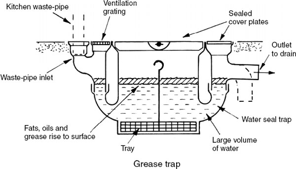
Correctly sized, a grease trap will retain about 50% of fats, etc. Greater effect can be achieved by installing more than one in series. It is a Building Regulation requirement (Approved Document H1, Section 2.21) for all new and refurbished commercial hot food preparation premises to have an effective means of grease removal from waste water before it discharges to a public drain or sewer. Grease separators complying with BS EN 1825 will satisfy this.
Refs. BS EN 1825–1: Grease separators. Principles of design, performance and testing, marking and quality control.
BS EN 1825–2: Grease separators. Selection of nominal size, installation, operation and maintenance.
The Public Health Act prohibits discharge of petroleum and oil into a sewer. Garage floor washings will contain petrochemicals and these must be prevented from entering a sewer. The floor layout should be arranged so that one garage gully serves up to 50m2 of floor area. The gully will retain some oil and other debris, which can be removed by emptying the inner bucket. A petrol interceptor will remove both petrol and oil. Both rise to the surface with some evaporation through the vent pipes. The remaining oil is removed when the tanks are emptied and cleaned. The first chamber will also intercept debris and this compartment will require more regular cleaning. Contemporary petrol interceptors are manufactured from reinforced plastics for simple installation in a prepared excavation.

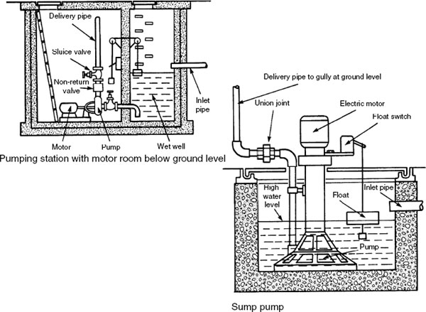
The contents of drainage pipelines should gravitate to the sewer and sewage processing plant. In some situations site levels or basement sanitary facilities will be lower than adjacent sewers and it becomes necessary to pump the drainage flows. A pumping station or plant room can be arranged with a motor room above or below surface level. Fluid movement is by centrifugal pump, usually immersed and therefore fully primed. For large schemes, two pumps should be installed with one on standby in the event of the duty pump failing. The pump impeller is curved on plan to complement movement of sewage and to reduce the possibility of blockage. The high-level discharge should pass through a manhole before connecting to the sewer.

Refs. BS EN 12056–4: Gravity drainage systems inside buildings. Waste water lifting plants. Layout and calculation.
BS EN 12050: Waste water lifting plants for buildings and sites.
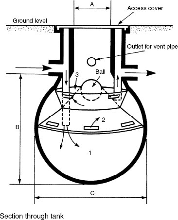
A sewage ejector may be used as an alternative to a centrifugal pump for lifting foul water. The advantages of an ejector are:
Less risk of blockage.
Fewer moving parts and less maintenance.
A wet well is not required.
One compressor unit can supply air to several ejectors.
Operation:
Incoming sewage flows through inlet pipe A into ejector body B.
Float rises to the top collar.
Rod is forced upwards, opening an air inlet valve and closing an exhaust valve.
Compressed air enters the ejector body, forcing sewage out through pipe C.
The float falls to the bottom collar and its weight plus the rocking weight closes the air inlet valve and opens the exhaust valve.

Ref. BS EN 1671: Pressure sewerage systems outside buildings.
When considering methods of drainage pumping, equipment manufacturers should be consulted with the following details:
Drainage medium – foul or surface water, or both.
Maximum quantity – anticipated flow in m3/h.
Height to which the sewage has to be elevated.
Length of delivery pipe.
Availability of electricity – mains or generated.
Planning constraints, regarding appearance and siting of pump station.
I n the interests of visual impact, it is preferable to construct the motor room below ground. This will also absorb some of the operating noise. In basements there may be some infiltration of ground water. This can be drained to a sump and pumped out as the level rises. In plant rooms a sump pump may be installed to collect and remove water from any leakage that may occur. It is also useful for water extraction when draining down boilers for servicing.
Ref. Design guidance for external pumped installations may be found in BS EN’s 12050–1 and 3: Wastewater lifting plants for buildings and sites.
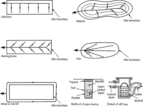
Ideally, buildings should be constructed with foundations above the subsoil water table. Where this is unavoidable or it is considered necessary to generally control the ground water, a subsoil drainage system is installed to permanently lower the natural water table. Various ground drainage systems are available; the type selected will depend on site conditions. The simplest is a French drain. It comprises a series of strategically located rubble-filled trenches excavated to a fall and to a depth below high water table. This is best undertaken after the summer, when the water table is at its lowest. Flow can be directed to a ditch, stream or other convenient outfall. In time the rubble will become silted up and need replacing.
An improvement uses a polyethylene/polypropylene filament fabric membrane to line the trench. This is permeable in one direction only and will also function as a silt filter. This type of drain is often used at the sides of highways with an open rubble surface.

The layout and spacing of subsoil drainage systems depends on the composition and drainage qualities of the subsoil and the disposition of buildings. For construction sites the depth of drainage trench will be between 600mm and 1·5m. Shallower depths may be used in agricultural situations and for draining surface water from playing fields. Installation of pipes within the rubble drainage medium has the advantage of creating a permanent void to assist water flow. Suitable pipes are produced in a variety of materials, including clay (open jointed porous or perforated) concret (porous (no-fine aggregate) or perforated) and uPVC (perforated). The pipe void can be accessed for cleaning and the system may incorporate silt traps at appropriate intervals. Piped outlets may connect to a surface water sewer with a reverse-acting interceptor trap at the junction.
Note: The installation of subsoil drainage may be necessary under Building Regulation provisions. The purpose of this is to prevent the passage of ground moisture into a building and the possibility of damage to a building.
Ref. Approved Document C, Section 3: Subsoil drainage.
British Standard pipes commonly used for subsoil drainage:
Perforated clay, BS EN 295–5.
Porous clay, BS 1196.
Profiled and slotted plastics, BS 4962.
Perforated uPVC, BS 4660.
Porous concrete, BS withdrawn no manufacturing interest.
Silt and other suspended particles will eventually block the drain unless purpose-made traps are strategically located for regular cleaning. The example shown on the previous page is adequate for short drain runs, but complete systems will require a pit which can be physically accessed. This is an essential requirement if the drain is to connect to a public surface water sewer. In order to protect flow conditions in the sewer, the local water authority may only permit connection via a reverse-acting interceptor trap. This item does not have the capacity to function as a silt trap.

Drains must be tested before and after backfilling trenches.
Air test – the drain is sealed between access chambers and pressure tested to 100mm water gauge with hand bellows and a ‘ U’ gauge (manometer). The pressure must not fall below 75mm during the first five minutes.
Smoke test – may be used to detect leakage. The length of drain to be tested is sealed and smoke pumped into the pipes from the lower end. The pipes should then be inspected for any trace of smoke. Smoke pellets may be used in the smoke machine, or with clay and concrete pipes they may be applied directly to the pipeline.
Water test – effected by stopping the lower part of the drain and filling the pipe run with water from the upper end. This requires a purpose-made test bend with an extension pipe to produce a 15m head of water. This should stand for two hours and if necessary topped up to allow for limited porosity. For the next 30 minutes, maximum leakage for 100mm and 150mm pipes is 0·05 and 0·08 litres per metre run respectively.

Where a surface water sewer is not available, it may be possible to dispose of rainwater into a soakaway. A soakaway will only be effective in porous soils and above the water table. Water must not be allowed to flow under a building and soakaways should be positioned at least 3m away (most local authorities require 5m). A filled soakaway is inexpensive to construct, but it will have limited capacity. Unfilled or hollow soakaways can be built of pre-cast concrete or masonry.
Soakaway capacity can be determined by applying a rainfall intensity of at least 50mm per hour to the following formula:
![]()
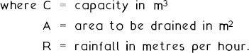
E.g. a drained area of 150m2
![]()

Note: BRE Digest 365: Soakaways, provides a more detailed approach to capacity calculation. BRE also produce the soakaway design software, BRESOAK.
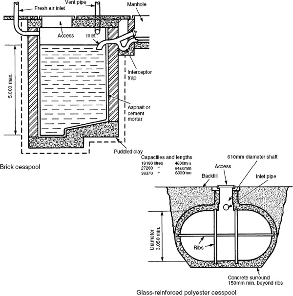
A cesspool is an acceptable method of foul water containment where main drainage is not available. It is an impervious chamber requiring periodic emptying, sited below ground level. Traditional cesspools were constructed of brickwork rendered inside with waterproof cement mortar. Pre-cast concrete rings supported on a concrete base have also been used, but factory-manufactured glass reinforced plastic units are now preferred. The Building Regulations require a minimum capacity below inlet level of 18000 litres. A cesspool must be impervious to rainwater, well ventilated and have no outlets or overflows. It should be sited at least 15m from a dwelling.
Capacity is based on 150 litres per person per day at 45-day emptying cycles, e.g. a four-person house:
![]()
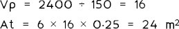
Where main drainage is not available a septic tank is preferable to a cesspool. A septic tank is self-cleansing and will only require annual desludging. It is in effect a private sewage disposal plant, which is quite common for buildings in rural areas. The tank is a watertight chamber in which the sewage is liquefied by anaerobic bacterial activity. This type of bacteria lives in the absence of oxygen which is ensured by a sealed cover and the natural occurrence of a surface scum or crust. Traditionally built tanks are divided into two compartments with an overall length of three times the breadth. Final processing of sewage is achieved by conveying it through subsoil drainage pipes or a biological filter. Capacity is determined from the simple formula:
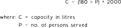
E.g. 10 persons; C = (180 × 10) + 2000 = 3800 litres (3·8 m3).
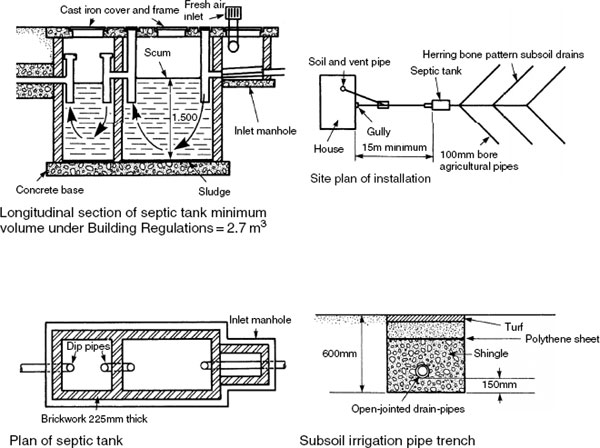
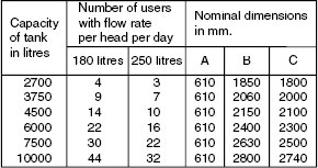
Klargester Settlement/Septic Tank
The Klargester settlement tank is a simple, reliable and cost-effective sewage disposal system manufactured from glass-reinforced plastics for location in a site-prepared excavation. A standard range of tanks are produced in capacities ranging from 2700 to 10000 litres, to suit a variety of applications from individual houses to modest developments including factories and commercial premises. The sewage flows through three compartments (1,2,3) on illustration where it is liquefied by anaerobic bacterial activity. In similarity with traditionally built tanks, sludge settlement at the base of the unit must be removed annually. This is achieved by pushing away the floating ball to give extraction tube access into the lowest chamber. Processed sewage may be dispersed by subsoil irrigation or a biological filter.
Ref. Building Regulations, Approved Document H2: Waste water treatment systems and cesspools.
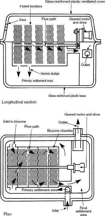
Biodisc Sewage Treatment Plant
The biological disc has many successful applications to modest-sized buildings such as schools, prisons, country clubs, etc. It is capable of treating relatively large volumes of sewage by an accelerated process. Crude sewage enters the biozone chamber via a deflector box which slows down the flow. The heavier solids sink to the bottom of the compartment and disperse into the main sludge zone. Lighter solids remain suspended in the biozone chamber. Within this chamber, microorganisms present in the sewage adhere to the partially immersed slowly rotating discs to form a biologically active film feeding on impurities and rendering them inoffensive. Baffles separate the series of rotating fluted discs to direct sewage through each disc in turn. The sludge from the primary settlement zone must be removed every six months.
Treatment of septic tank effluent – liquid effluent from a septic tank is dispersed from a rotating sprinkler pipe over a filter of broken stone, clinker, coke or polythene shingle. The filter surfaces become coated with an organic film which assimilates and oxidises the pollutants by aerobic bacterial activity. This type of bacteria lives in the presence of oxygen, encouraged by ventilation through under-drains leading to a vertical vent pipe. An alternative process is conveyance and dispersal of septic tank effluent through a system of subsoil drains or a drainage field. To succeed, the subsoil must be porous and the pipes laid above the highest water table level. Alternatively, the primary treated effluent can be naturally processed in constructed wetland phragmite or reed beds (see page 351). Whatever method of sewage containment and processing is preferred, the local water authority will have to be consulted for approval.

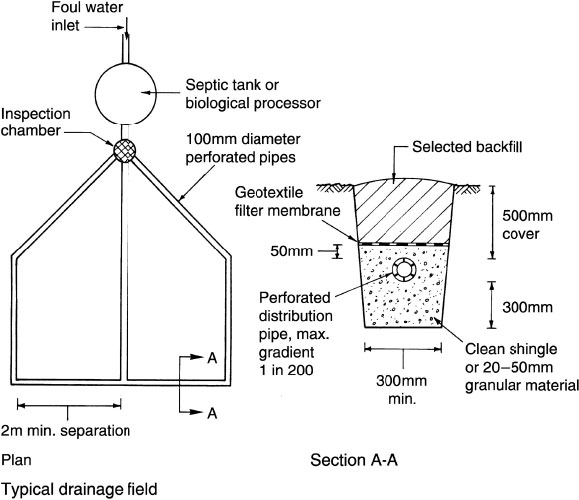
Drainage fields and mounds are a less conspicuous alternative to the use of a biological filter for secondary processing of sewage. Disposal and dispersal is through a system of perforated pipes laid in a suitable drainage medium.
Location:
Min. 10m from any watercourse or permeable drain.
Min. 50m from any underground water supply.
Min. distance from a building:
<5 people
15m
6–30 people
25m
31–00 people,
40m
>100 people
70m
Downslope of any water source.
Unencroached by any other services.
Unencroached by access roads or paved areas.
Ground quality:
Preferably granular, with good percolation qualities. Subsoils of clay composition are unlikely to be suited.
Natural water table should not rise to within 1m of distribution pipes invert level.
Ground percolation test:
Dig several holes 300 × 300mm, 300mm below the expected distribution pipe location.
Fill holes to a 300 mm depth of water and allow to seep away overnight.
Next day refill holes to 300mm depth and observe time in seconds for the water to fall from 225mm depth to 75mm. Divide time by 150mm to ascertain average time (Vp) for water to drop 1mm.
Apply floor area formula for drainage field:
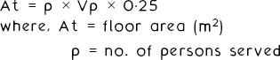
e.g. 40min (2400 secs) soil percolation test time in a system serving six persons.
Note: Vp should be between 12 and 100. Less than 12 indicates that untreated effluent would percolate into the ground too rapidly. A figure greater than 100 suggests that the field may become saturated.
Typical constructed drainage mound

Reed Beds and Constructed Wetlands
These provide a natural method for secondary treatment of sewage from septic tanks or biological processing equipment.
Common reeds (Phragmites australis) are located in prepared beds of selected soil or fine gravel. A minimum bed area of 20m2 is considered adequate for up to four users; 5m2 should be added for each additional person. Reeds should be spaced about every 600mm and planted between May and September. For practical purposes application is limited to about 30 people, due to the large area of land occupied. Regular maintenance is necessary to reduce unwanted weed growth which could restrict fluid percolation and natural processing. The site owners have a legal responsibility to ensure that the beds are not a source of pollution, a danger to health or a nuisance.

Ref. Building Regulations, Approved Document H2: Waste water treatment systems and cesspools.
Sustainable Urban Drainage Systems (SUDS)
Extreme weather situations in the UK have led to serious property damage from flooding, as drains, rivers and other watercourses are unable to cope with the unexpected volumes of surface water. A possible means of alleviating this and moderating the flow of surface water is the construction of SUDS between the drainage system and its outfall.
Objectives are to:
decrease the volume of water discharging or running off from a site or building
reduce the run-off rate
filter and cleanse the debris from the water flow.
Formats:
soakaways
swales
infiltration basins and permeable surfaces
filter drains
retention or detention ponds
reed beds.
Soakaways – See page 343. For application to larger areas, see BS EN 752: Drain and sewer systems outside buildings.
Swales – Channels lined with grass. These slow the flow of water, allowing some to disperse into the ground as they convey water to an infiltration device or watercourse. They are best suited to housing, car-parks and roads.
Infiltration basins and permeable surfaces – Purposely located depressions lined with grass and positioned to concentrate surface water into the ground. Permeable surfaces such as porous asphalt or paving can also be used to the same effect.
Filter drains – Otherwise known as French drains (see page 339). Note that drainage may be assisted by locating a perforated pipe in the centre of the gravel or rubble filling.
Retention or detention ponds – These are man-made catchments to contain water temporarily, for controlled release later.
Reed beds – These are not restricted to processing septic tank effluent, as shown on page 351. They are also a useful filter mechanism for surface water, breaking down pollutants and settlement of solids.
Ref. Sustainable Urban Drainage Systems – Design manual for England and Wales – (C 522) and for Scotland and N. Ireland (C 521) – CIRIA.
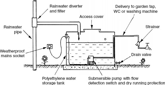
In terms of demand, fresh water is becoming a relatively scarce resource, resulting in an ongoing programme by the water authorities to meter water consumption to all buildings. Rainwater harvesting is an economic means for supplementing the use of processed water, thereby reducing utilities bills and impact on the environment. The process involves intercepting, storing and filtering the surface water runoff from roofs and hard landscaping. Some applications to rainwater drainage systems are shown below.
Typical domestic garden application –
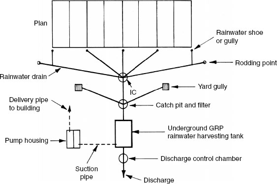
Typical commercial/industrial site application –
The Code for Sustainable Homes (see page 43) sets objectives for domestic water consumption at various levels of progression. The requirement for the year 2016 is a maximum consumption of 80 litres per person per day from the current maximum of 125 litres per person per day (2010 Building Regulation G2).
Although old technology, updating and applying the concept of harvested water is a major contributor to attaining water consumption economies.
Anticipated benefits –
Domestic mains water consumption reduced by up to 50%.
Water consumption within commercial premises with large roof areas reduced by up to 75% where there is high usage of sanitary fitments.
Water captured from rainfall run-offs is directed through filters, stored and recycled as illustrated on the previous page.
Requirements –
Separate pipework from mains-supplied potable/wholesome water.
No direct connection between harvested water and mains-supplied water.
Pipework conveying harvested water to be marked and labelled with clear identification “ … so as to be easily distinguished from any supply pipe or distributing pipe”. Some examples of identification could be RECLAIMED WATER, UNWHOLESOME WATER, NON- POTABLE WATER or WATER NOT FOR HUMAN CONSUMPTION. Extract from Schedule 2, Para. 14 The Water Supply (Water Fittings) Regulations.
Non-potable, harvested rainwater must be fully serviced/supplied (topped up) even during periods of dry weather. Therefore a non- potable water storage vessel must have a mains water top-up facility via an air gap or header tank as a backflow prevention installation.
A harvested water storage tank overflow pipe is required to provide controlled discharge during heavy rainfall. This should run off via a drain into an adequately sized soakaway or storm water drainage system.
Ref. BS 8515: Rainwater harvesting systems. Code of practice.
Separation of water supplies – there must be no possibility of crossconnection between a pipe conveying wholesome water and a pipe conveying harvested rainwater or any other type of unwholesome water. Where a mains supply of wholesome water is used to top up a vessel containing harvested rainwater, backflow prevention is essential. Mechanical pipeline fittings such as double-check valves and variable backflow preventers with reduced pressure zone (RPZ valve) are not sufficient (see pages 54 and 55). Backflow prevention is by air gap separation, as shown below.

Marking and labelling – pipes conveying reclaimed water must be labelled (see previous page) and identified with a BS 1710 colour coding to distinguish them from other pipeline services. Storage vessels and valves should also be identified. The examples show green as the basic colour for water. See pages 695 and 696 for others.

Ref. BS 1710: Specification for identification of pipelines and services.
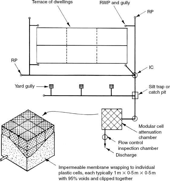
Rainwater attenuation applies to controlling and managing rainfall run-off from buildings and hard landscaping. In many situations this can be achieved with soakaways or with retention/detention ponds. An alternative is an underground retention and discharge process that uses a system of fabricated plastic modular cells. The individual units, similar in appearance to milk crates, are tied or clipped together to create a matrix. These can be made up to an overall size large enough to accommodate the run-off demands for numerous buildings. The completed matrix is wrapped in an impermeable membrane, but this can be partially omitted if a soakaway facility is required.
Drainage Design – Surface Areas
The size of gutters and downpipes will depend on the effective surface area to be drained. For flat roofs this is the plan area, while pitched roof effective area (Ae) can be calculated from:
![]()
Roofs over 70° pitch are treated as walls, with the effective area taken as: Elevational area × 0·5.
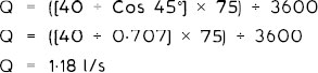
Actual rainfall varies throughout the world. For UK purposes, a rate of 75mm/h (R) is suitable for all but the most extreme conditions. Rainfall runoff (Q) can be calculated from:
![]()
E.g. a 45° pitched roof of 40 m2 plan area.
Size of gutter and downpipe will depend on profile selected, i.e. half round, ogee, box, etc. Manufacturers’ catalogues should be consulted to determine a suitable size. For guidance only, the following is generally appropriate for half-round eaves gutters with one end outlet:
Half-round gutter (mm) |
Outlet dia. (mm) |
Flow capacity (l/s) |
|---|---|---|
75 |
50 |
0·38 |
1 00 |
65 |
0·78 |
1 15 |
65 |
1·11 |
1 25 |
75 |
1·37 |
1 50 |
90 |
2·16 |
Therefore the example of a roof with a flow rate of 1·18 l/s would be adequately served by a 125mm gutter and 75mm downpipe.
Where an outlet is not at the end, the gutter should be sized to the larger area draining into it.
The distance between a stopped end and an outlet should not exceed 50 times the flow depth.
The distance between two or more outlets should not exceed 100 times the flow depth (see example below).
For design purposes, gutter slope is taken as less than 1 in 350.
E.g. a 100mm half-round gutter has a 50mm depth of flow, therefore:
![]()
Ref. Building Regulations, Approved Document H3: Rainwater Drainage.
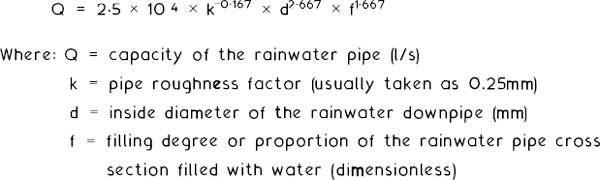
Another method of rainwater downpipe sizing is provided in BS EN 12056–3: Gravity drainage systems inside buildings. Roof drainage, layout and calculations. This Standard provides tabulated data calculated from the Wyly-Eaton equation to determine the capacity of rainwater pipes:
d (mm) |
Q (l/s) |
f |
|---|---|---|
65 |
1·5 |
0·20 |
65 |
3·4 |
0·33 |
75 |
2·2 |
0·20 ( see calculation below) |
75 |
5·0 |
0·33 |
90 |
3·5 |
0·20 |
90 |
8·1 |
0·33 |
1 00 |
4·6 |
0·20 |
1 00 |
0·7 |
0·33 |
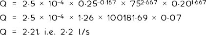
Example by calculation for a 75mm diameter rainwater pipe with a filling degree of 02:
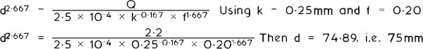
To calculate rainwater pipe diameter the formula is rearranged:
This alternative procedure can be seen to allow a greater amount of flow capacity than that indicated on the previous page.
When designing rainfall run-off calculations for car parks, playgrounds, roads and other made-up areas, a rainfall intensity of 50mm/h is considered adequate. An allowance for surface permeability (P) should be included, to slightly modify the formula from page 357:
![]()
Permeability factors:
Asphalt |
0·85–0.95 |
Concrete |
0·85–0.95 |
Concrete blocks (open joints) |
0·40–0.50 |
Gravel drives |
0·15–0.30 |
Grass |
0·05–0.25 |
Paving (sealed joints) |
0·75–0.85 |
Paving (open joints) |
0·50–0.70 |
E.g. a paved area (P = 0.75) 50m × 24m (1200m2).
![]()
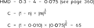
The paved area will be served by several gullies (at 1 per 300m2 = 4) with subdrains flowing into a main surface water drain. Each drain can be sized according to the area served, but for illustration purposes only the main drain is considered here. The pipe sizing formula is:

Drains should not be designed to flow full bore as this leaves no spare capacity for future additions. Also, fluid flow is eased by the presence of air space. Assuming half full bore, using the above figure of 0.0125m3/s, and the minimum velocity of flow of 0.75 m/s:
![]()
Transposing,
![]()
This represents the area of half the pipe bore, so the total pipe area is double, i.e. 0·034 m2.
Area of a circle (pipe) = πr2 where r = radius of pipe (m).
Transposing,
Therefore the pipe diameter = 2 × 04 = 208mm.
The nearest commercial size is 225 mm nominal inside diameter.
Drainage Design – Velocities and Hydraulic Mean Depth
Velocity of flow – 0·75m/s is the accepted minimum to achieve self-cleansing. It is recognised that an upper limit is required to prevent separation of liquids from solids. A reasonable limit is 1·8m/s for both surface and foul water drainage, although figures up to 3m/s can be used especially if grit is present. The selected flow rate will have a direct effect on drain gradient, therefore to moderate excavation costs a figure nearer the lower limit is preferred. Also, if there is a natural land slope and excavation is a constant depth, this will determine the gradient and velocity of flow.
Hydraulic mean depth (HMD) – otherwise known as hydraulic radius represents the proportion or depth of flow in a drain. It will have an effect on velocity and can be calculated by dividing the area of water flowing in a drain by the contact or wetted perimeter. Thus for half full bore:

This table summarises HMD for proportional flows:
Depth of flow |
HMD |
|---|---|
0·25 |
Pipe dia. (m) ÷ 6·67 |
0·33 |
Pipe dia. (m) ÷ 5·26 |
0·50 |
Pipe dia. (m) ÷ 4·00 |
0·66 |
Pipe dia. (m) ÷ 3·45 |
0·75 |
Pipe dia. (m) ÷ 3·33 |
Full |
Pipe dia. (m) ÷ 4·00 |
E.g. a 225mm (0–225m) drain flowing half bore:
![]()
Drainage Design – Depth of Flow
Drains are usually designed with a maximum flow condition of three- quarters full bore, i.e. depth of flow or proportional depth 0·75. It is essential to maintain some air space within a drain to prevent pressure variations. Half full bore is a more conservative design, allowing ample space for future connections and extensions to the system.
The relationship between drain capacity or proportional depth of flow, velocity of flow (m/s) and discharge (m3 /s) is represented in graphical format:

Taking the example on page 365, the drain is designed to flow at half full bore with a flow velocity of 0·8m/s and discharge of 0·052m3/s. If at some later date additional buildings are connected to the drainage system to produce an anticipated flow of up to 0·75 proportional depth, the graph indicates revised relative velocity and discharge rates of 114% or 0·912m/s and 92% or 0·048m3/s, respectively.
The fall, slope or inclination of a drain or sewer will relate to the velocity of flow and the pipe diameter. The minimum diameter for surface water and foul water drains is 75mm and 100mm respectively.
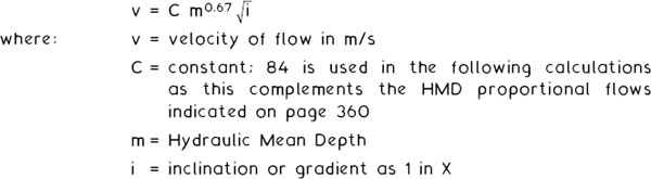
Maguire’s rule of thumb is an established measure of adequate fall on drains and small sewers. Expressing the fall as 1 in×, where 1 is the vertical proportion to horizontal distance×, then:
![]()
E.g. a 150mm nominal bore drain pipe:
![]()
Pipe dia.(mm) |
Gradient |
|---|---|
1 00 |
1 in 40 |
1 50 |
1 in 60 |
225 |
1 in 90 |
300 |
1 in 120 |
For full and half bore situations, these gradients produce a velocity of flow of about 1·4m/s.
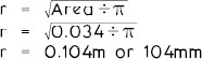
The Building Regulations, Approved Documents H1 and H3, provide guidance on discharge capacities for surface water drains running full and foul water drains running 075 proportional depth. The chart below is derived from these data:
Notes: (1) − − = Rainwater only. (2) 75mm is for rainwater or waste water (no soil) only. (3) To convert l/s to m3/s. divide bv 1000.
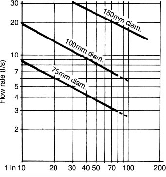
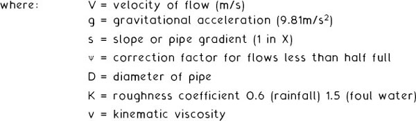
An alternative approach to drainage design is attributed to the established fluid flow research of Antoine Chezy and Robert Manning. This can provide lower gradients:
Chezy’s formula: ![]()
Mannings formula: ![]()

*A figure of 0·010 is appropriate for modern high-quality uPVC and clay drainware – for comparison purposes it could increase to 0·015 for a cast concrete surface.
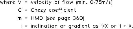
E.g. A 300mm (0·3m) nominal bore drain-pipe flowing 0–5 proportional depth (half full bore). The Chezy coefficient can be calculated from Manning’s formula:
Using a velocity of flow shown on the previous page of 1·4m/s, the minimum gradient can be calculated from Chezy’s formula:

Drainage Design – Derivation of Formulae
Chezy formula – attributed to experiments that determined the relationship between fluid flow in open channels relative to the velocity of flow. In 1775 the Frenchman, Antoine Chezy, published his formula which has since become the practical basis for drainage design calculations:
![]()
Chezy’s C cannot be evaluated as a pure number or as a constant. It has the dimensions of acceleration, i.e. ![]() where L is the length of drain run and T is time. Chezy’s C is therefore a coefficient affected by the hydraulic mean depth (m) and the pipe surface roughness (n).
where L is the length of drain run and T is time. Chezy’s C is therefore a coefficient affected by the hydraulic mean depth (m) and the pipe surface roughness (n).
Kutter and Ganguillet formula – these Swiss engineers determined a factor for channel and pipe surface roughness (n) for a variety of materials ranging from glass (0·009) to rough timber (0·160). For purposes of modern pipe materials, these values or coefficients range from 0·010 to 0–015 as qualified on the previous page. On the basis of their research, in 1869 Kutter and Ganguillet produced a formula for evaluating Chezy’s C:
![]()
where s is expressed as the sine of the bed slope or drain inclination.
Manning formula – following the earlier work of Kutter and Ganguillet,
Manning formula – following the earlier work of Kutter and Ganguillet, in 1888 the Irish engineer Robert Manning produced his much simpler formula for the Chezy coefficient:
![]()
The value of pipe surface roughness (n) being attributed to Kutter and Ganguillet. It is often referred to as Kutter’s n.
Although extremely dated and some quite empirical in their formulation, these formulae have stood the test of time. They are still favoured by engineers and drainage designers and continue to feature in research and product development.
Drainage Design – Foul Water (1)
Small drainage schemes:
< 20 dwellings, 100mm nom. bore pipe, min. gradient 1 in 80.
20–150 dwellings, 150mm nom. bore pipe, min. gradient 1 in 150.
Minimum size for a public sewer is 150mm. Most water authorities will require a pipe of at least 225mm to allow for future developments and additions to the system.
For other situations, estimates of foul water flow may be based on water consumption of 225 litres per person per day. A suitable formula for average flow would be:
![]()
Note: 6 hours is assumed for half daily flow.
E.g. A sewer for an estate of 500, four-person dwellings:
![]()
Assuming maximum of five times average flow = 52l/s or 0·052m3/s.
Using the formula Q = V × A (see page 359) with a velocity of flow of, say, 0·8m/s flowing half full bore (0–5 proportional depth):
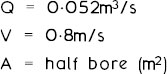
Transposing the formula:
![]()
A represents half the bore, therefore the full bore area = 0·130m2.
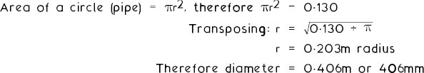
Nearest commercial size is 450mm nominal bore.
An alternative approach to estimating drain and sewer flows is by summation of discharge units and converting these to a suitable pipe size. Discharge units represent frequency of use and load producing properties of sanitary appliances. They are derived from data in BS EN 12056–2 and BS EN 752, standards for drainage systems inside and outside buildings, respectively. Although intended primarily for sizing discharge stacks, they are equally well applied to drains and sewers.
Appliance |
Situation |
No. of units |
|---|---|---|
WC |
Domestic |
7 |
Commercial |
14 | |
Public |
28 | |
Basin |
Domestic |
1 |
Commercial |
3 | |
Public |
6 | |
Bath |
Domestic |
7 |
Commercial |
18 | |
Sink |
Domestic |
6 |
Commercial |
14 | |
Public |
27 | |
Shower |
Domestic |
1 |
Commercial |
2 | |
Urinal |
0·3 | |
Washing machine |
4–7 | |
Dishwasher |
4–7 | |
Waste disposal unit |
7 | |
Group of WC, bath and one or two basins |
14 | |
Other fittings with an outlet of: |
||
50 mm nom. i.d. |
7 | |
65 mm nom. i.d. |
7 | |
75 mm nom. i.d. |
10 | |
90 mm nom. i.d. |
10 | |
100 mm nom. i.d. |
14 | |
Note:
Domestic = houses and flats.
Commercial = offices, factories, hotels, schools, hospitals, etc.
Public or peak = cinemas, theatres, stadia, sports centres, etc.
Using the example from page 365, i.e. 500, four-person dwellings. Assuming one WC, one shower, two basins, two sinks, one group of appliances, washing machine and dishwasher per dwelling.
WC |
7 |
discharge units |
Shower |
1 |
discharge unit |
Basins |
2 |
discharge units |
Sinks |
12 |
discharge units |
Group |
14 |
discharge units |
Washing machine |
4 |
discharge units |
Dishwasher |
4 |
discharge units |
Total = 44 discharge units × 500 dwellings = 22000 discharge units.
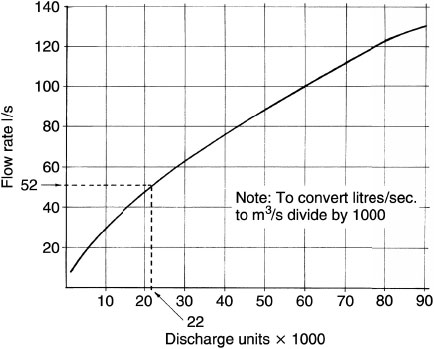
Sewer size can be calculated for a 0052m3/s flow at half full bore using the formula Q = V × A as shown on page 365. Gradient can be calculated using the Chezy and Manning formulas as shown on page 363.
Combined surface and foul water drains will require separate calculations for both flow conditions. Drain size can be based on the greater flow, not the total flow, as the chance of the peak flows of both coinciding is remote.
See pages 438 and 439 for alternative ‘K’ factor method of drainage design.
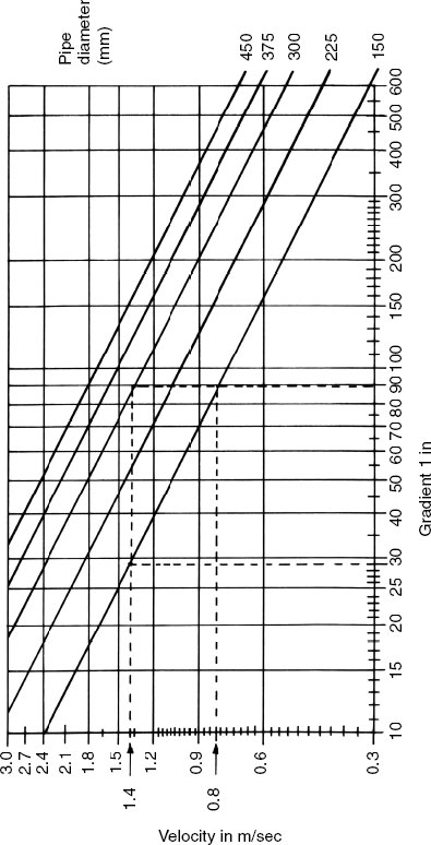
Drainage Design – Gradient and Velocity
Adaptation of Kutter and Ganguillet’s formulations for pipe sizes, gradients and velocity where n = 0.013 and HMD is diameter ÷ 4, i.e. half and full bore.
Example shown is for a flow velocity of 1.4m/s in a 300mm pipe laid to a gradient of 1 in 90. The same flow velocity in a 150mm pipe requires a gradient of 1 in 29. A 150mm pipe at 1 in 90 has a velocity of 0.8m/s.
Drainage Design – Gradient and Discharge
Adaptation of Kutter and Ganguillet’s formulations for pipe sizes, gradients and discharge rates where n = 0.013 and HMD is diameter ÷ i.e. half and full bore.
Examples shown are from the previous page, with pipes of 150mm dia. graded at 1 in 29 and 300mm dia. at 1 in 90.

Drainage Design – Further Formulae (1)
Crimp and Bruges’ formula – during the mid-1890s William Crimp and Charles Bruges formulated an adaptation of Kutter and Ganguillet’s earlier work on fluid flow analysis. They produced a simplified evaluation of flow velocity in drains and sewers based on the following:
Note: C, not compared with or confused with Chezy’s constant.
HMD0.67 or m0.67 can also be expressed as ![]()
Therefore: ![]()
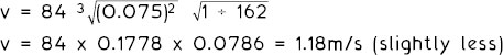
E.g. 1. Taking the example on page 363 of a 300mm drain flowing half bore at a minimum gradient of 1 in 162 with a flow velocity of 1.4m/s. Using Crimp and Bruge’s formula the velocity of flow can be compared:
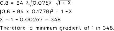
E.g. 2. Using the formula to calculate the minimum gradient for a 300mm pipe flowing half bore discharging at a flow rate of 0.8m/s.
E.g. 3. A 150mm pipe flowing 0.75 depth of flow at 0.8m/s:
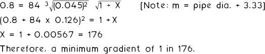
Therefore, a minimum gradient of 1 in 176.
C.F. Colebrook and C.M. White formula • an equation devised in the late 1930s based on theory and experimentation of partial flows in drains and sewers:
![]()
As can be seen, the Colebrook/White calculation is quite extensive and very time consuming to use. Fortunately, their formulations are available graphically and the reader is referred to the Thomas Telford publication Gravity Flow Pipe Design Tables by D. Butler and B.R.C. Pinkerton, where numerous charts are available for a wide range of pipe sizes and applications.
Since the mid-twentieth century there have been many more theories and research applications into fluid flow and hydraulic conditions in drainage pipes. Consistency of results remains somewhat elusive as can be seen from the outcome of various calculations over the preceding pages. Therefore, no new theory is propounded here, nor any of the formulae used suggested as best. They are for guidance and reference only as a basis for further study.
Factors outside of calculation and laboratory experimentation will inevitably affect flow conditions in drains. These may include the quality of workmanship during installation, irregular settlement of pipes, leakage, possible ingress of tree roots and later additions to the system. With regard to these, it is for drainage consultants and engineers to determine their own design criteria based on theoretical guidance and personal experience, and to produce specifications with regard to the practicalities of site characteristics.
The quantity and location of refuse chutes depends upon:
layout of the building
number of dwellings served – max. six per hopper
type of material stored
frequency of collection
volume of refuse
refuse vehicle access – within 25m.
The chute should be sited away from habitable rooms, but not more than 30m horizontal distance from each dwelling. It is more economical to provide space for additional storage beneath the chute, than to provide additional chutes. Chute linings are prefabricated from refractory or Portland cement concrete with a smooth and impervious internal surface. The structure containing the chute void should have a fire resistance of one hour. The refuse chamber should also have a one hour fire resistance and be constructed with a dense impervious surface for ease of cleaning.

Ref. BS 5906: Waste management in buildings. Code of practice.
On-Site Incineration of Refuse
This system has a flue to discharge the incinerated gaseous products of combustion above roof level. A fan ensures negative pressure in the discharge chute to prevent smoke and fumes from being misdirected. A large combustion chamber receives and stores the refuse until it is ignited by an automatic burner. Duration of burning is thermostatically and time controlled. Waste gases are washed and cleaned before discharging into the flue. There is no restriction on wet or dry materials, and glass, metal or plastics may be processed.
Health risks associated with storing putrefying rubbish are entirely eliminated as the residue from combustion is odourless and sterile. Refuse removal costs are reduced because the residual waste is only about 10% of the initial volume.
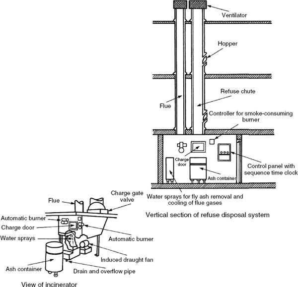
Incinerators are the quickest, easiest and most hygienic method for disposing of dressings, swabs and sanitary towels. They are usually installed in office lavatories, hospitals and hotels. When the incinerator door is opened, gas burners automatically ignite and burn the contents. After a predetermined time, the gas supply is cut off by a time switch. Each time the door is opened, the time switch reverts to its original position to commence another burning cycle. Incinerators have a removable ash pan and a fan-assisted flue to ensure efficient extraction of the gaseous combustion products. In event of fan failure, a sensor ensures that gas burners cannot function. The gas pilot light has a thermocoupled flame failure device.

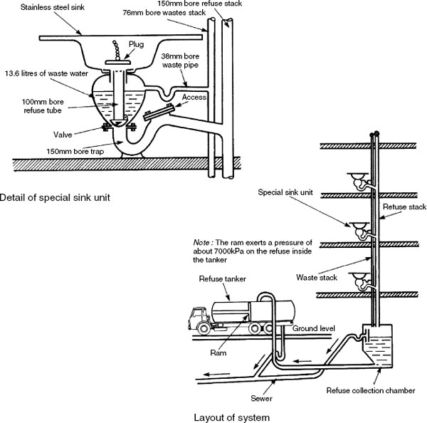
The Matthew-Hall Garchey System
Food waste, bottles, cans and cartons are disposed of at source, without the need to grind or crush the refuse. A bowl beneath the sink retains the normal waste water. Refuse is placed inside a central tube in the sink. When the tube is raised the waste water and the refuse are carried away down a stack or discharge pipe to a chamber at the base of the building. Refuse from the chamber is collected at weekly intervals by a specially equipped tanker in which the refuse is compacted into a damp, semi-solid mass that is easy to tip. One tanker has sufficient capacity to contain the refuse from up to 200 dwellings. Waste water from the tanker is discharged into a foul water sewer.
Refuse from conventional chutes is collected in a pulveriser and disintegrated by grinder into pieces of about 10mm across. The refuse is then blown a short distance down a 75mm bore pipe in which it is retained, until at predetermined intervals a flat disc valve opens. This allows the small pieces of refuse to be conveyed by vacuum or airstream at 75 to 90km/h through a common underground service pipe of 150–300mm bore. The refuse collection silo may be up to 25km from the source of refuse. At the collection point the refuse is transferred by a positive pressure pneumatic system to a treatment plant where dust and other suspended debris is separated from bulk rubbish. The process can be adapted to segregate salvagable materials such as metals, glass and paper.

Food waste disposal units are designed for application to domestic and commercial kitchen sinks. They are specifically for processing organic food waste and do not have the facility to dispose of glass, metals, rags or plastics. Where a chute or Garchey system is not installed, these units may be used to reduce the volume otherwise deposited in dustbins or refuse bags.
Food waste is fed through the sink waste outlet to the unit. A grinder powered by a small electric motor cuts the food into fine particles which is then washed away with the waste water from the sink. The partially liquefied food particles discharge through a standard 40mm nominal bore waste pipe into a back inlet gully. As with all electrical appliances and extraneous metalwork, it is essential that the unit and the sink are earthed.

Ref. BS EN 60335–2–16: Household and similar electrical appliances. Safety, Particular requirements for food waste disposers.