
13 Fire Prevention and Control Services
Smoke, Fire and Heat Detectors
Fire Detection Electrical Circuits
Fire Prevention in Ventilating Systems
Pressurisation of Escape Routes
Water sprinklers provide an automatic spray dedicated to the area of fire outbreak. Sprinkler heads have temperature-sensitive elements that respond immediately to heat, discharging the contents of the water main to which they are attached. In addition to a rapid response which reduces and isolates fire damage, sprinklers use less water to control a fire than the firefighting service, therefore preventing further damage from excess water.
Sprinkler systems were initially credited to an American, Henry Parmalee, following his research during the late 1800s. The idea was developed further by another American, Frederick Grinnell, and the name ‘Grinnell’ is still associated with the glass-type fusible element sprinkler head.
Domestic pipework – solvent cement bonded, post-chlorinated polyvinyl chloride (CPVC).
Industrial and commercial pipework – threaded galvanised mild steel.
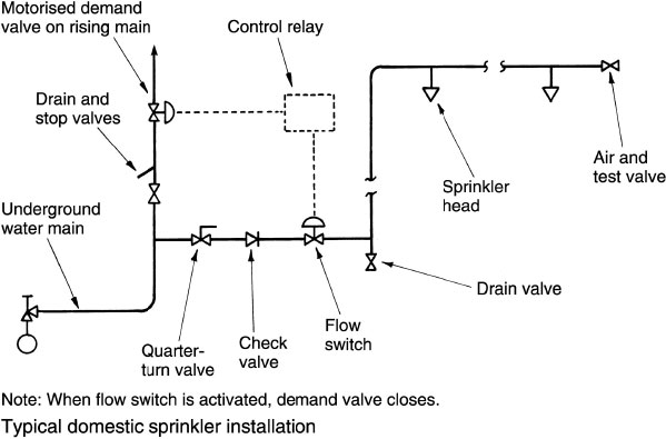
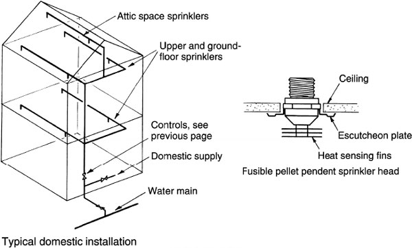
The simplest application is to attach and suspend sprinkler heads from a water main fixed at ceiling level. However, some means of regulation and control is needed and this is shown in the domestic application indicated below.
Refs. BS EN’s 12259-1 to 5: Fixed firefighting systems. Components for sprinkler and water spray systems.
BS EN 12845: Fixed firefighting systems. Automatic sprinkler systems. Design, installation and maintenance.
Sprinklers – Domestic Installations
Pipe materials – Copper tube – BS EN 1057 | |
Post-chlorinated Polyvinylchloride (CPVC) | |
System – mains supplied, wet.
Pipe sizes – 25mm min. i.d. incoming service to supply at least 60l/min. through any one sprinkler head, or 42l/min. through any two sprinkler heads operating simultaneously in the same room.
Sprinkler head spacing – area covered by one head, max. 12m2.
Maximum distance between heads – 4m.
Maximum distance from wall to ceiling mounted head – 2m.
Minimum distance between heads in the same room – 2m (only one head per room is normal).
Operating pressure – Minimum 0.5 bar (50kPa).
Ref. BS 9251: Sprinkler systems for residential and domestic occupancies. Code of practice.
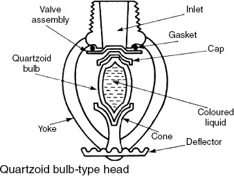
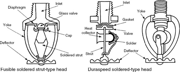
Quartzoid bulb – a glass tube is used to retain a water valve on its seating. The bulb or tube contains a coloured volatile fluid, which when heated to a specific temperature expands to shatter the glass and open the valve. Water flows on to a deflector, dispersing as a spray over the source of fire. Operating temperatures vary with a colour-coded liquid:
Orange – 57°C
Red – 68°C
Yellow – 79°C
Green – 93°C
Blue – 141°C
Mauve – 182°C
Black – 204 or 260°C
Fusible strut – has two metal struts soldered together to retain a water valve in place. A range of solder melting temperatures are available to suit various applications. Under heat, the struts part to allow the valve to discharge water on the fire.
Duraspeed solder type – contains a heat collector which has a soldered cap attached. When heat melts the solder, the cap falls away to displace a strut, allowing the head to open. Produced in a range of operating temperatures.
The specification of a sprinkler system will depend on the purpose intended for a building, its content, function, occupancy, size and disposition of rooms. Installations to commercial and industrial premises may be of the following type:
Wet system – the simplest and most widely used application. The pipework is permanently charged with water. It is only suitable in premises where temperatures remain above zero, although small sections of exposed pipework could be protected by trace element heating. The maximum number of sprinklers on one control valve is 1000 (see page 597).
Dry system – an air-charged system applied to unheated premises such as warehousing, where winter temperatures could drop below zero. The maximum number of sprinklers on one control valve is 250, but this may increase to 500 if the air controls include an accelerator (see page 598).
Alternative wet and dry system – essentially a wet system, but due to the slightly slower response time as air precedes water on discharge, the pipework is charged with water for most of the year and only air charged in winter. The maximum number of sprinklers is the same as a dry system (see page 598).
Tail-end system – used in a building with different internal functions, e.g. a mix of office accommodation with an unheated storage facility. The installation differs from an alternative wet and dry system, as most of the pipework is permanently charged with water. Only those pipes in parts of a building exposed to sub-zero temperatures are charged with air and these are designed as additions (tail ends) to a wet system. The wet and tail-end parts are separated by a compressed air control valve. As the system is essentially wet, the maximum number of sprinklers may be 1000. The maximum number after a tail-end air control valve is 100, with no more than 250 in total on tail-end air valves in one installation.
Pre-action system – used where there is a possibility that sprinkler heads may be accidently damaged by tall equipment or plant, e.g. a fork-lift truck. To avoid unnecessary water damage, the system is dry. If a sprinkler head is damaged, compressed air discharges and an initial alarm is activated. Water will only be supplied to the damaged sprinkler if a ceiling-mounted heat detector senses a temperature rise. The sensor will open a motorised valve on the water supply and effect another alarm. Detectors have a lower temperature rating than the sprinkler; therefore, for a 68°C head, the detector will be set at about 60°C. Max. number of sprinklers is 1000.
Recycling pre-action system – a variation of the pre-action system, designed as a damage-limiting installation. After sprinklers have subdued a fire, a heat detector responds to a lower temperature and disengages the water supply after a five-minute delay. If the fire restarts and temperature rises, the detector re-engages a motorised valve on the water supply. Maximum number of sprinklers is 1000.
Cycling wet system – in principle similar to the recycling pre-action system except it is a normal wet system. It functions in conjunction with ceiling heat detectors which will disengage the water supply within a predetermined time of the temperature dropping. If the temperature rises, the water supply will be automatically turned on again.
In addition to the considerations for system selection given on the preceding page, the building insurer will probably have greatest influence in determining the final specification. Insurer’s requirements are likely to be formulated from guidance in:
The Building Regulations, Approved Document B: Fire safety.
BS EN 12845: Fixed firefighting systems. Automatic sprinkler systems.
The Loss Prevention Certification Board’s Loss Prevention Standards.
The Loss Prevention Certification Board was formed in 1985 as an incorporation of the Fire Offices’ Committee (FOC), the Fire Insurers Research and Testing Organisation and the Fire Protection Association. Rules for design and installation originally produced by the FOC are now included in the British Standard.
Buildings are assessed by fire risk and categorised by fire load’ as a hazard according to their purpose and content:
Light hazard (LH) – low fire load and containing no single compartment exceeding 126m2 floor area with fire resistance of at least 30min. Examples include educational premises, prisons and offices. Maximum protected area is 10 000m2 per control valve.
Ordinary hazard (OH 1 to OH 4) – medium fire load category such as process or manufacturing premises.
OH 1 – cement works, sheet metal processors, dairies, abattoirs, hospitals, hotels, offices, schools and restaurants.
OH 2 – garages (car workshops), laboratories, bakeries, food processors, breweries, car-parks and museums.
OH 3 and 4 – industrial processors and warehouses with combustible stored products.
High hazard – high fire load categories typical of warehouses containing combustible products in high racking systems. Fireworks factories and some chemical processes will also be included.
Note: Where specified, sprinklers should be installed in all parts of a building. Some exception may be permitted for toilets, washrooms and enclosed stairways.
*Fire load – an assessment of the combustible potential of materials contained within a building. Fire load is expressed as the heat potential per unit area, as a calorific value in Joules/m2.
Grade 1 (low) – 1150MJ/m2. e.g. hotels, hospitals, schools, public libraries, offices, flats, restaurants, museums, sports centres and institutions.
Grade 2 (moderate) – 1150–2300MJ/m2. e.g. retail premises, factories and workshops.
Grade 3 (high) – 2300–4600MJ/m2. workshops, manufacturing processes and warehousing where combustible materials are deployed, e.g. timber and paper fabrication.
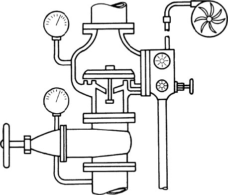
The wet system is used in heated buildings where there is no risk of the water in the pipework freezing. All pipework is permanently pressure charged with water and the sprinkler heads usually attach to the underside of the range pipes. Where water is mains supplied, it should be fed from both ends. If the main is under repair on one side, the stop valve and branch pipe can be closed and the sprinkler system supplied from the other branch pipe.
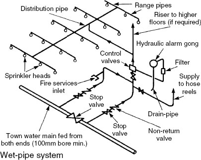
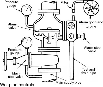
When a sprinkler head is fractured, water is immediately dispersed. Water will also flow through an annular groove in the alarm valve seating to a pipe connected to an alarm gong and turbine. A jet of water propels the turbine blades, causing the alarm gong to operate. Pipeline flow switches will alert the local fire service in addition to operating an internal alarm system. Except under supervised maintenance, the main stop valve is padlocked in the open position.
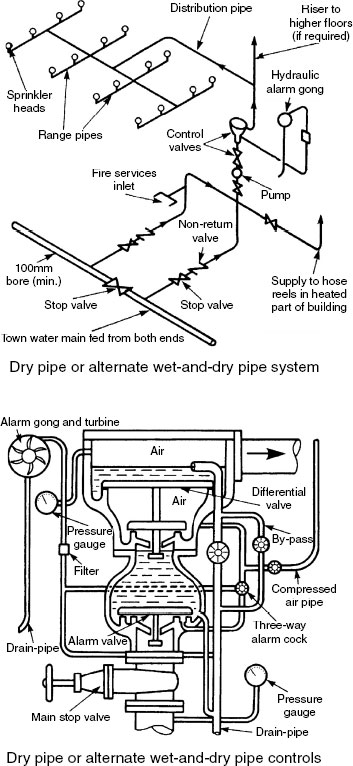
Dry and Alternate Wet-and-dry Sprinkler Installations
Dry or an alternate wet-and-dry sprinkler system may be used in buildings that are unheated.
Dry system – installation pipework above the differential valve is permanently charged with compressed air. When a fire fractures a sprinkler head, the compressed air escapes to allow the retained water to displace the differential valve and flow to the broken sprinkler.
Alternate wet-and-dry system – a wet system for most of the year, but during the winter months it functions as a dry system.
The dry part of the system above the diaphragm or differential valve is charged with compressed air at about 200kPa. Any loss of pressure is automatically replenished by a small compressor, but this will not interfere with water flow if the system is activated. When a sprinkler is fractured, an automatic booster pump can be used to rapidly exhaust the air and improve water flow. Sprinkler heads are fitted above the range pipes which are slightly inclined to allow the system to be fully drained.
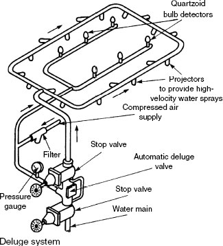
Deluge and Multiple Control Sprinklers
Deluge system – used for specifically high fire hazards such as plastic foam manufacture, fireworks factories, aircraft hangars, etc., where there is a risk of intensive fire with a very fast rate of propagation. The pipework is in two parts: compressed air with quartzoid bulbs attached and a dry pipe with open-ended spray projectors. When a fire occurs, the quartzoid bulbs shatter and compressed air in the pipeline is released, allowing a diaphragm inside the deluge control valve to open and discharge water through the open pipe to the projectors.
Multiple control system – a heat-sensitive sealed valve controls the flow of water to a small group of open sprayers attached to a dry pipe. When a fire occurs, the valve quartzoid bulb shatters, allowing the previously retained water to displace the valve stem and flow to the sprayers. An alternative to a heat-sensitive valve is a motorised valve activated by a smoke or fire detector.

Water Supplies for Sprinkler Systems
There are various sources of water supply that may be used for sprinkler applications.
Elevated private reservoir – minimum volume varies between 9m3 and 875m3 depending on the size of installation served.
Suction tank – supplied from a water main. Minimum tank volume is between 2.5m3 and 585m3. A better standard of service may be achieved by combining the suction tank with a pressure tank, a gravity tank or an elevated private reservoir. A pressure tank must have a minimum volume of water between 7m3 and 23m3. A pressure switch or flow switch automatically engages the pump when the sprinklers open.
Gravity tank – usually located on a tower to provide sufficient head or water pressure above the sprinkler installation.
River or canal – strainers must be fitted on the lowest part of the suction pipes corresponding with the lowest water level. Duplicate pumps and pipes are required, one diesel and the other electrically powered.
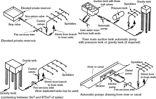
Note: Water source capacities, pressures, delivery rates, etc. vary with application. See tables for specific situations in BS 5306-2: Fire extinguishing installations and equipment on premises. Specification for sprinkler systems.
Pipework Distribution to Sprinklers
The arrangement of pipework will depend on the building shape and layout, the position of the riser pipe and the number of sprinkler heads required. To provide a reasonably balanced distribution, it is preferable to have a centre feed pipe. In practice this is not always possible and end feed arrangements are used. The maximum spacing of sprinkler heads (s) on range pipes depends on the fire hazard classification of the building.
Hazard category |
Max. spacing (s) of sprinkler heads (m) |
Max. floor area covered by one sprinkler head (m2) |
|---|---|---|
Light |
4·6 |
21 |
Ordinary |
4·0 (standard) |
12 |
4·6 (staggered)* |
12 | |
High |
3·7 |
9 |
* See next page
For side wall-mounted sprinklers, the maximum floor area coverage by one sprinkler head is 17m2 for light hazard and 9m2 for ordinary hazard.

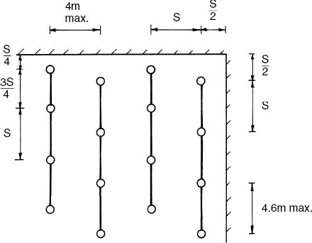
Further Pipework Distribution and Spacing Calculations
Staggered arrangement of sprinkler heads on an ordinary hazard installation:
Calculating the number of sprinkler heads: e.g. an ordinary fire hazard category for a factory having a floor area 20m × 10m.
![]()
Ordinary hazard requires a maximum served floor area of 12 m2 per sprinkler head.
Therefore: 200 ÷ 12 = 16·67, i.e. at least 17 sprinkler heads.
For practical purposes, 18 could be installed as shown:
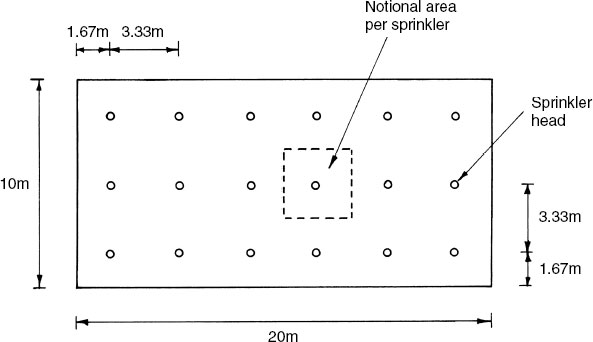
The maximum area served by each sprinkler head = 3·33m × 3·33m = 11·1m2.
This is satisfactory, being less than 12m2.
Sprinkler pipe installations downstream of the alarm and control valves should be sized by hydraulic calculation, with regard to system pressure and friction losses (see Part 2).
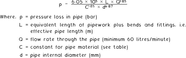
Tabulated data for pipe sizing is available in BS EN 12845 and CIBSE Guide E: Fire engineering. It is also possible to determine pipe diameters from the Hazen-Williams friction loss formula:
Pipe material |
Constant (C) |
|---|---|
Cast iron |
100 |
Steel |
120 |
Stainless steel |
140 |
Copper |
140 |
CPVC |
150 |
Maximum water velocity through valves is 6m/s. Through any other part of the system, 10m/s.
By determining an acceptable pressure loss as a design prerequisite, the Hazen-Williams formula can be rearranged with the pipe diameter as the subject:
![]()
e.g. Calculate the diameter of 30m effective length steel pipe, where the acceptable pressure loss is 0·02 bar with a water flow rate of 60litres/minute.
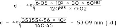
50mm nominal inside diameter is just too small; therefore a 65mm nominal inside diameter steel pipe would be selected.
A drencher fire control system provides a discharge of water over roofs, walls and windows to prevent fire from spreading either from or to adjacent buildings. Automatic drenchers are similar in operating principle to individual quartzoid bulb sprinkler heads. A manually operated stop valve can also be used with dry pipes and open spray nozzles. This stop valve must be located in a prominent position with unimpeded access. Installation pipework should fall to a drain valve positioned at the lowest point above the stop valve. The number of drencher nozzles per pipe is similar to the arrangements for conventional sprinkler installations as indicated in BS 5306-2. For guidance, two drenchers can normally be supplied by a 25mm i.d. pipe. A 50mm i.d. pipe can supply ten drenchers, a 75mm i.d. pipe 36 drenchers and a 150mm i.d. pipe over 100 drenchers. An example of application is in theatres, where the drenchers may be fitted above the proscenium arch at the stage side to protect the safety curtain.

Hose reels are firefighting equipment for use as a first-aid measure by building occupants. They should be located where users are least likely to be endangered by the fire, i.e. the staircase landing. The hose most distant from the source of water should be capable of discharging 0.4l/s at a 6m distance from the nozzle, when the two most remote hose reels are operating simultaneously. A pressure of 200 kPa is required at the highest reel. If the water main cannot provide this, a break/suction tank and booster pumps should be installed. The tank must have a minimum volume of water of 1.6 m3 A 50 mm i.d. supply pipe is adequate for buildings up to 15m height and a 65mm i.d. pipe will be sufficient for buildings greater than this. Fixed or swinging hose reels are located in wall recesses at a height of about 1 m above floor level. They are supplied by a 25mm i.d. pipe to 20 or 25mm i.d. reinforced non-kink rubber hose in lengths up to 45m to cover 800 m2 of floor area per installation.
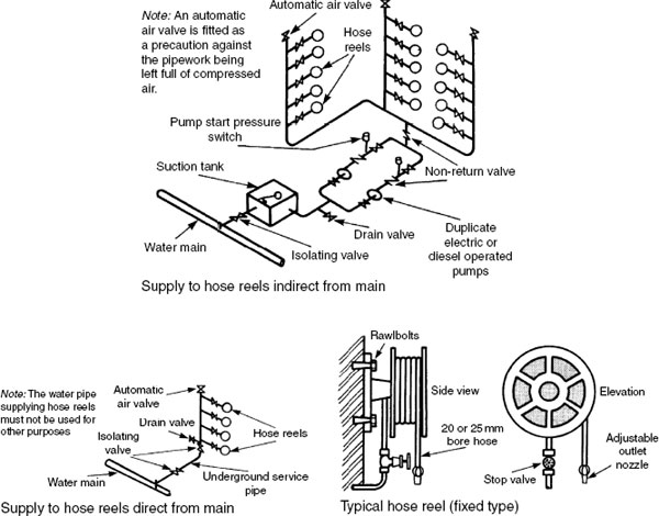
Ref. BS 5306-1: Code of practice for fire extinguishing installations and equipment on premises. Hose reels and foam inlets.
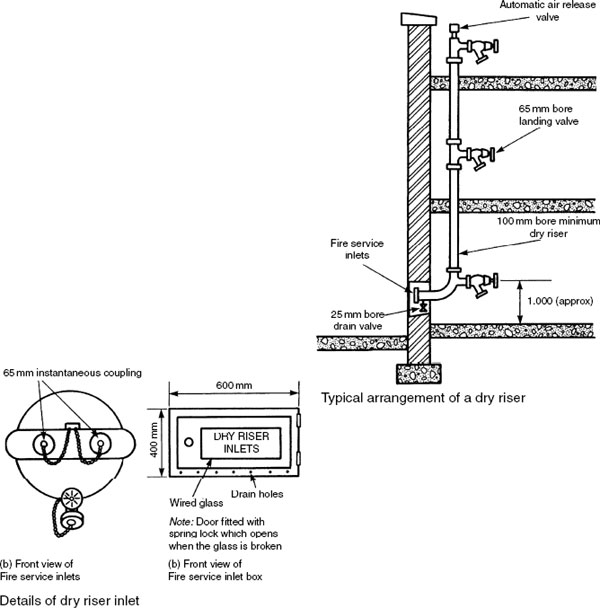
A dry riser is in effect an empty vertical pipe which becomes a firefighter’s hose extension to supply hydrants at each floor level. Risers should be disposed so that no part of the floor is more than 60 m from a landing valve. This distance is measured along a route suitable for a firefighting hose line, to include any dimension up or down a stairway. Buildings with floors up to 45m above fire service vehicle access level require one 65mm landing valve on each floor from a 100mm i.d. riser. Buildings between 45m and 60m with one or two landing valves per floor require a 150 mm i.d. riser. For buildings above 60 m a wet riser must be installed. Two 65 mm i.d. inlet hose couplings are required for a 100 mm riser and four 65 mm i.d. inlets are required for a 150 mm riser. The riser must be electrically bonded to earth.
Note: A dry riser is installed either in unheated buildings or where the water main will not provide sufficient pressure at the highest landing valve. A hard standing for the fire service vehicle is required at the base of the riser. One landing valve is required for every 900m2 of floor area.
A wet riser is suitable in any building where hydrant installations are specified. It is essential in buildings where floor levels are higher than that served by a dry riser, i.e. greater than 60m above fire service vehicle access level. A wet riser is constantly charged with water at a minimum running pressure of 400kPa with up to three most remote landing valves operating simultaneously. A flow rate of 25l/s is also required. The maximum pressure with one outlet open is 500kPa to protect firefighting hoses from rupturing. Orifice plates may be fitted to the lower landing valves to restrict pressure. Alternatively, a pressure relief valve may be incorporated in the outlet of the landing valve. The discharge from this is conveyed in a 100mm i.d. drain-pipe.
To maintain water at the required pressure and delivery rate, it is usually necessary to install pumping equipment. Direct pumping from the main is unacceptable. A suction or break tank with a minimum water volume of 45m3 is used with duplicate power source service pumps. One 65mm landing valve should be provided for every 900m2 floor area.
Note: In addition to the supply through the float valves the suction tank should also be supplied with a 150mm fire service inlet.

A pump-operated mechanical foam installation consists of a foam concentrate tank located outside of the area to be protected. The tank has a water supply pipe inlet and foam pipe outlet. A venture is fitted in the pipeline to draw the foam out of the tank. When the water pump is switched on, the venturi effect causes a reduction in pressure at the foam pipe connection, resulting in a mixture of foam concentrate and water discharging through the outlet pipe.
A pre-mixed foam installation consists of a storage tank containing foam solution. When a fire occurs in the protected area, a fusible link is broken to release a weight which falls to open a valve on the carbon dioxide cylinder. Foam solution is forced out of the tank at a pressure of about 1000kPa to discharge over the protected equipment, e.g. an oil tank.

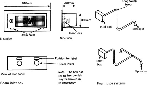
A foam installation is used for application from remote points on to flammable liquid fire risks. This type of installation is often used with oil-fired boilers and oil storage tanks. A foam access box is built into the wall at an easily accessible place for firefighters to attach hoses from their foam-generating and mixing equipment. The box is usually located about 600mm above adjacent ground and should be clear of any openings through which heat, smoke or flames can pass. The glass-fronted box can be broken and the lock released from inside. Two 65mm diameter inlets may be used. A 65 or 75mm i.d. galvanised steel pipe is normally used for the distribution. A maximum pipework length of 18m is recommended and this must slope slightly towards the spreaders. Vertical drop pipes are acceptable but vertically inclined pipes must not be used. Spreader terminals are positioned about 1m above oil burners and about 150mm above oil-spill level of stored fuel.
Ref. BS EN 13565-2: Fixed firefighting systems. Foam systems. Design, construction and maintenance.
Gas Extinguishing Systems – Halon and Halon Substitutes
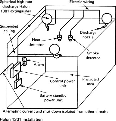
The majority of gas extinguishing systems have been either halon 1301 or carbon dioxide (see next page). Halons are electrically non-conductive and in this respect safe to use where personnel remain in an area of gas discharge. They are also more effective than carbon dioxide, being five times the density of air, while carbon dioxide is only one-and-a-half times. Unfortunately halon or bromochlorodifluoromethane (BCF) gases are a hazard to the environment, by contributing significantly to the depleting effect of the ozone layer. In 1987 a meeting of major countries at a Montreal convention agreed to phase out the use of these gases by 2002. Therefore, except for systems installed in less cooperative countries, new installations will contain halon substitutes. These include inergen and argonite, both mixtures of nitrogen and argon, the former containing a small amount of carbon dioxide.
In principle, the systems are suitable where there is a high density of equipment, e.g. tape libraries and computer suites where an alternative wet system would be considered too damaging. Gas is stored in spherical steel containers which can be secured in a ceiling or floor void or against a wall. When activated by smoke or heat, detectors immediately open valves on the extinguishers to totally flood the protected area with a colourless and odourless gas.
Ref. BS 5306-5.1: Code of practice for fire extinguishing installations and equipment on premises. Halon systems. Specification for halon 1301 total flooding systems.
Gas Extinguishing Systems – Carbon Dioxide
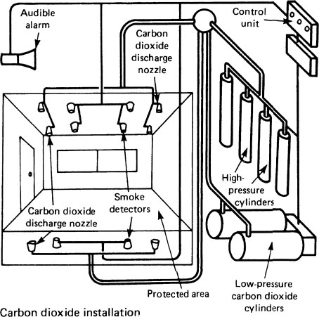
Carbon dioxide is an alternative to halon as a dry gas extinguisher. It has been used as an extinguishing agent for a considerable time, particularly in portable extinguishers. As the gas is dry and non-conductive it is ideal for containing fires from electrical equipment, in addition to textiles, machinery, petroleum and oil fires. Carbon dioxide is heavier than air and can flow around obstacles to effectively reduce the oxygen content of air from its normal 21% to about 15%. This considerably reduces an important component of the combustion process (see page 627). Integrated high- and low-pressure gas systems may be used, with the former operating at up to 5800kPa. Systems can be either electrical, pneumatic or mechanical with a manual override facility. Carbon dioxide is potentially hazardous to personnel; therefore it is essential that the system is automatically locked off when the protected area is occupied. In these circumstances it can be switched to manual control. Airtightness of a protected room is essential for the success of this system as total flooding relies on gas containment by peripheral means.
Ref. BS 5306. 4: Fire extinguishing installations and equipment on premises. Specification for carbon dioxide systems.
In the UK, the Fire Service attend over half a million fires per year. These fires result in over 800 deaths and many more injuries. About one-tenth of all fires occur in homes and account for some 500 deaths and thousands of injuries. An early warning device to detect smoke and fire could significantly reduce the number of human casualties.
Since 1992 The Smoke Detectors Act requires all new homes to have a smoke detection facility. Detectors are available in two basic types. Each can be powered by a simple battery cell or by mains electricity. The latter will normally have battery back-up if the mains supply fails.
lonisation – an inexpensive device, sensitive to tiny smoke particles and fast-burning fires such as a flaming chip pan (page 615).
Light scattering or optical – more expensive but more sensitive in slow-burning and smouldering fire produced by burning fabrics or upholstery and overheating PVC wiring (page 615).
Combined – a unit containing both ionisation and optical detection.
Number and location – the more the better, as fires can start anywhere. Ideally detectors should be provided in every room except a bathroom, as dampness and steam can create a false affect. Likewise, for a kitchen, unless of sufficient volume to be unaffected by cooking appliances and washing-up facilities. Use in a garage can also be deceptive as exhaust fumes are likely to trigger the detector.
Minimum protection – one detector for every floor level positioned in a central hallway and/or landing. Building Regulation requirements for dwellings are summarised on pages 613–614. For other building purposes brief mention only is given on page 614, as different situations have varying requirements. Therefore the Approved Document should be consulted for specific applications.
Refs. Building Regulations, Approved Document B, Fire safety, Volume 1: Dwellinghouses, and Volume 2: Buildings other than dwellinghouses.
BS EN 54: Fire detection and alarm systems.
Fire detection and alarm systems may contain:
system control unit
primary (mains) electrical supply
secondary (battery or capacitor stand-by) power supply; an emergency generator could also be used
alarm activation devices – manual or automatic
alarm indication devices – audible and/or visual
remote indication on a building monitoring system
control relay via a building management system to effect fire extinguishers and ventilation smoke control actuators.
System control unit – an alarm panel which monitors the state of all parts (zones) of the installation. It identifies the point of origin of an alarm, displays this on the panel and communicates this to remote control locations.
Zones:
Max. 2000m2 floor area in one storey.
No detachment of compartment areas within one floor area zone.
Max. 30m search distance into a zone.
Single occupancy of a zone where several separate business functions occur in one building.
Requirements for dwellings
Automatic fire detection and alarm systems are to be provided to the recommendations of BS 5839: Fire detection and alarm systems in buildings. They may comply with Part 1 or 6 of the BS, i.e. Code of practice for system design, installation, commissioning and maintenance, or Code of practice for the design and installation of fire detection and alarm systems in dwellings, respectively. Alternatively, a smoke alarm system may be acceptable if it complies with BS EN 14604: Smoke alarm devices. These should have primary and secondary power supplies.
Point detectors – individual heat or smoke detection units which respond to an irregular situation in the immediate vicinity.
Line detectors – a continuous type of detection comprising a pair of conducting cables separated by low-temperature melting insulation to permit a short-circuit alarm when the cables contact. Suitable in tunnels and service shafts.
Provision in large houses (> 1 storey):
Floor area |
Storeys (exc. basement) |
System |
|---|---|---|
>200m2/storey |
|
BS 5839-6, Grade A category LD2 |
>200m2/storey |
|
BS 5839-6, Grade B category LD3 |
Note: prefixes used in the BS categories indicates that L is a specific application to protection of life, whereas P indicates that for property.
Application:
Optical-type (photo-electric) detectors in circulation spaces, i.e. hallways, corridors and landings.
Ionisation-type detectors in living and dining areas.
Preferred location of detectors:
Over 300mm from light fittings.
Min. one per storey.
Loft conversions, with alarm linked to operate others and be operated by others in the dwelling.
Circulation spaces between bedrooms.
Circulation spaces <7.5m from doors to habitable rooms.
Kitchens (with regard to heat/smoke-producing appliances).
Living rooms.
Requirements for buildings other than dwellings:
This is less easy to define due to the variation in building types and patterns of occupancy. BS 5839 requirements may suit some buildings, but could cause panic in others, e.g. shopping centres, where people may be unfamiliar with the layout. In these situations, trained staff may be the preferred system of building evacuation. At building design stage, consultation between the local building control authority, the fire authority and the building’s insurer is paramount, as alterations post-construction are always extremely expensive.
Ref. Building Regulations, Approved Document B: Fire safety. Section B1: Fire detection and fire alarm systems.
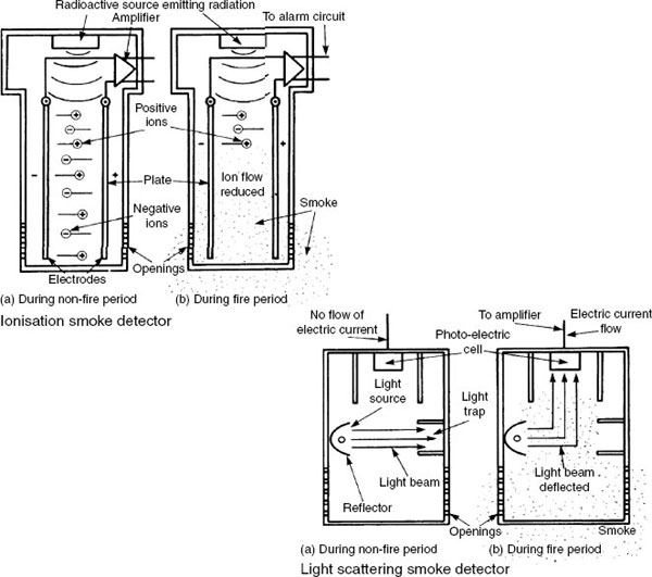
Ionisation smoke detector – positive and negative charged plate electrodes attract opposingly charged ions. An ion is an atom or a group of atoms which have lost or gained one or more electrons, to carry a predominantly positive or negative charge. The movement of ions between the plates reduces the resistance of air, such that a small electric current is produced. If smoke enters the unit, particles attach to the ions slowing their movement. This reduction in current flow actuates an electronic relay circuit to operate an alarm.
Light scattering or optical smoke detector – a light beam projects onto a light trap into which it is absorbed. When smoke enters the detector, some of the light beam is deflected upward onto a photoelectric cell. This light energises the cell to produce an electric current which activates the alarm relay.
Ref. BS EN 14604: Smoke alarm devices.
Heat detectors are used where smoking is permitted and in other situations where a smoke detector could be inadvertently actuated by process work in the building, e.g. a factory. Detectors are designed to identify a fire in its more advanced stage, so their response time is longer than smoke detectors.
Fusible type – has an alloy sensor with a thin walled casing fitted with heat-collecting fins at its lower end. An electrical conductor passes through the centre. The casing has a fusible alloy lining and this functions as a second conductor. Heat melts the lining at a predetermined temperature, causing it to contact the central conductor and complete an alarm relay electrical circuit.
Bimetallic coil type – heat passes through the cover to the bimetal coils. Initially the lower coil receives greater heat than the upper coil. The lower coil responds by making contact with the upper coil to complete an electrical alarm circuit.

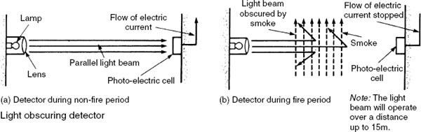
Light Obscuring and Laser Beam Detectors
Light obscuring – a beam of light is projected across the protected area close to the ceiling. The light falls onto a photo-electric cell which produces a small electrical current for amplification and application to an alarm circuit. Smoke rising from a fire passes through the light beam to obscure and interrupt the amount of light falling on the photo-electric cell. The flow of electric current from the cell reduces sufficiently to activate an alarm relay.
A variation is the light-scatter type. In normal use the light is widely dispersed and no light reaches the photo-electric cell receptor. In the presence of smoke, particulates deflect light onto the receptor to energise the cell.
Laser beam – a band of light which can be visible or infra-red projected onto a photo-electric cell. It does not fan out or diffuse as it travels through an uninterrupted atmosphere. The beam can operate effectively at distances up to 100m. If a fire occurs, smoke and heat rises and the pulsating beam is deflected away from the cell or reduced in intensity. As the cell is de-energised, this effects on alarm relay.

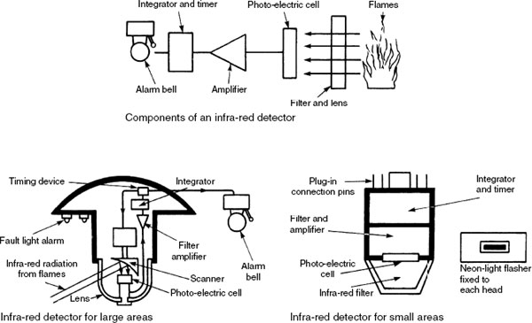
In addition to producing hot gases, fire also releases radiant energy in the form of visible light, infra-red and ultraviolet radiation. Radiant energy travels in waves from the fire.
Infra-red detector – detectors have a selective filter and lens to allow only infra-red radiation to fall on a photo-electric cell. Flames have a distinctive flicker, normally in the range of 4 to 15 Hz. The filter is used to exclude signals outside of this range. The amplifier is used to increase the current from the photo-electric cell. To reduce false alarms, a timing device operates the alarm a few seconds after the outbreak of fire.
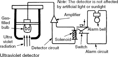
Ultraviolet detector – these detectors have a gas-filled bulb which reacts with ultraviolet radiation. When the bulb receives radiant energy, the gas is ionised to produce an electric current. When this current exceeds the set point of the amplifier the alarm circuit closes to operate the alarm system.
Fire Detection Electrical Circuits
Fire alarm electrical circuits may be of the ‘open’ or ‘closed’ types. In addition, or as an alternative to automatic smoke- or fire-sensing switches, manual break-glass alarm switches can be wall mounted at about 1.5m above floor level in lobbies, corridors and other common access locations. No person should have to travel more than 30m to use an alarm. In large managed buildings, a sub-circuit will connect to the facilities manager’s office or in more sophisticated situations the alarm can relay through telecommunications cables to a central controller and the fire service.
Open circuit – call points or detectors are connected to open switches, which prevent current from flowing through the circuit when it is on stand-by. Closing a switch on the detector circuit actuates a solenoid (electromagnet) to complete the alarm circuit. As there is no current flow while on stand-by there is no electrical power consumption. The disadvantage of this system is that if part of the detector circuit is inadvertently damaged, some of the switches will not operate.

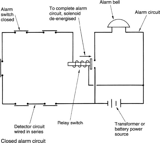
Electrical power to ‘open’ or ‘closed’ fire alarm circuits should be separate from any other electrical installation. To isolate it completely from any interruption to mains supply, it is usually transformed to 24–60 volts DC and provided with a battery back-up system in the event of the fire damaging the mains source of power.
Closed circuit – call points or detectors may be regarded as closed switches allowing current to flow in the detector circuit. This permanent current flow energises a solenoid switch which retains a break in the alarm circuit. When a detector circuit switch is operated (i.e. opened), the solenoid is de-energised, allowing a spring mechanism to connect it across the alarm circuit terminals and effect the alarm.
Ref. BS EN 54: Fire detection and fire alarm systems.
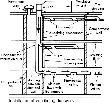
Fire Prevention in Ventilating Systems
Ventilation of services enclosures is required to dilute flammable, toxic or corrosive gases. This can be taken to include smoke and hot gases that will occur as a result of fire, particularly where the void contains combustible PVC cable sheathing and uPVC pipes. To provide a safe level of ventilation and to prevent overheating in a restricted enclosure, permanent natural ventilation should be at least 0.05m2 and 1/150 of the cross-sectional area for enclosure areas of less than 7.5m2 and greater than 7.5m2 respectively.
Openings and access panels into services enclosures should be minimal. The enclosure itself should be gas tight and there must be no access from a stairway. Where access panels or doors are provided they should be rated at not less than half the fire resistance of the structure, and have an integrity rating of at least 30 minutes (see BS 476-22). Fire doors should be fitted with self-closers.
Where ventilation ducts pass from one compartment to another or into a services enclosure, the void made in the fire-resisting construction must be made good with a suitable fire-stopping material. Automatic fire dampers are also required in this situation to prevent fire from spreading between compartments.
Refs. BS 8313: Code of practice for accommodation of building services in ducts.
BS 9999: Code of practice for fire safety in the design, management and use of buildings.
Building Regulations, Approved Document B3 (Section 7 Vol. 1 and Section 10 Vol. 2): Protection of openings and fire stopping.
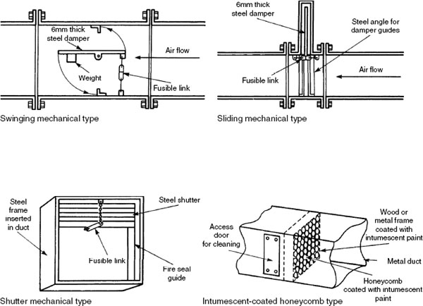
Fire Dampers in Ventilation Ductwork
Fire dampers are required in ventilation and air-conditioning systems to prevent smoke and fire from spreading through the ductwork to other parts of the building. Dampers should be positioned to maintain continuity of compartmentation by structural division. They can operate automatically by fusible link melting at a predetermined temperature of about 70’ C, to release a steel shutter. An electromagnet may also be used to retain the shutter in the open position. The electromagnet is deactivated to release the shutter by a relay circuit from a fire or smoke detector. The latter is preferable, as a considerable amount of smoke damage can occur before sufficient heat penetrates the ductwork to activate a heat detector or a fusible link.
An intumescent-coated honeycomb damper is an alternative. In the presence of heat, the coating expands to about a hundred times its original volume to form sufficient mass to impair the movement of fire through the duct. This type of damper has limited fire resistance and is only likely to be specified in low-velocity systems.
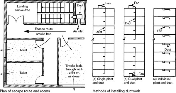
Pressurisation of Escape Routes
In multi-storey buildings, stairways and lobbies may be air pressurized to clear smoke and provide an unimpeded escape route. The air pressurisation is usually between 25 and 50Pa depending on the building height and degree of exposure. This pressure is insignificant for movement of personnel. A number of pressurisation methods may be used:
Pressurisation plant is disengaged, but it is automatically switched on by a smoke or fire detector.
Pressurisation plant runs fully during hours of occupancy as part of the building ventilation system.
Pressurisation plant runs continuously at a reduced capacity and output during the hours of building occupancy, but fire detection automatically brings it up to full output.
It is important to provide openings so that smoke is displaced from the escape routes to the outside air. This can be through purpose-made grilles or window vents. Pressurisation will help to limit entry of rain and draughts at external openings.
Ref. BS EN 12101-6: Smoke and heat control systems. Specification for pressure differential systems. Kits.
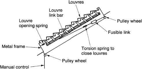
Smoke Extraction and Ventilation
Automatic fire ventilation is designed to remove heat, smoke and toxic gases from single-storey buildings. In large factories and shopping malls, the additional volume of air entering the building by fire venting is insignificant relative to the benefits of creating clear visibility. Parts of the roof can be divided into sections by using fireproof screens which may be permanent or may fall in response to smoke detection. Fire vents are fitted at the highest part of each roof section as is practical. Heat and smoke rise within the roof section above the fire outbreak. At a predetermined temperature, usually 70° C, a fusible link breaks and opens the ventilator above the fire. Heat and smoke escape to reduce the amount of smoke logging within the building. This will aid people in their escape and assist the fire service to see and promptly tackle the source of fire. The heat removed prevents risk of an explosion, flash-over and distortion to the structural steel frame.

Automatic smoke and fire ventilator:
Number and area of ventilators – estimates are based on providing a smoke-free layer about 3m above floor level.
E.g.
Floor to centre of vent height (m) |
Ventilation factor (m) |
|---|---|
4·5 |
0·61 |
7·5 |
0·37 |
10·5 |
0·27 |
13·5 |
0·23 |
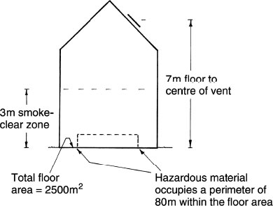
By interpolation, ventilation factor for 7m approximates to 0·41m. Ventilator area can be taken as the perimeter occupied by hazardous material, multiplied by the ventilation factor, i.e. 80m × 0·41m. This approximates to 33m2 or (33/2500 × 100/1) = 1·3% of the floor area.
Smoke Control in Shopping Malls
Most enclosed shopping centres have a mall with a parade of shops. The mall is the general circulation area and the obvious escape route from a fire. In these situations, a fire can generate a rapid spread of smoke and hot gases. It is therefore essential that some form of smoke control is adopted. If the central area has a normal (68° C) sprinkler system, the water may cool the smoke and hot gases to reduce their buoyancy and create an unwanted fogging effect at floor level. Therefore, consideration should be given to reducing the number of sprinkler heads and specifying a higher operating temperature. Smoke can be controlled by:
Providing smoke reservoirs into which the smoke is retained before being extracted by mechanical or natural means.
Allowing replacement cool air to enter the central area through low-level vents to displace the smoke flowing out at higher level.

A portable fire extinguisher must contain the type of fire-extinguishing agent suitable for the fire it is required to extinguish. It must also be clearly identifiable by colour coding for its intended purpose.
Fires can be classified as:
Class A – organic solids, e.g. wood, paper, cloth.
Class B – flammable liquids, e.g. petrol, oil, paint.
Class C – flammable gases, e.g. methane, propane, acetylene.
Class D – flammable metals, e.g. zinc, aluminium, uranium.
Electrical – not specifically classed because it can apply to any of the other classifications.
Class F – cooking oil and fat.
Extinguishing agent |
Extinguisher colour |
Application/Class |
|---|---|---|
Water |
Red |
A |
Foam |
Red with cream band |
A and B |
Carbon dioxide |
Red with black band |
B and Electrical |
Dry chemicals/powder |
Red with blue band |
A, B, C and Electrical |
Wet chemicals |
Red with yellow band |
A and F |
Special powders |
Red with blue band |
D |
Refs. BS EN 3: Portable fire extinguishers.
BS 7863: Recommendations for colour coding to indicate the extinguishing media contained in portable fire extinguishers.
Extinguisher rating – performance rating and capability can be identified by a letter relative to Class types A to D and F, and a number. The higher the number the larger the fire that the extinguisher is capable of controlling as determined under British Standard test conditions, e.g. 13A and 55B.
Some extinguishers have two or three letter ratings to indicate the range of capability. Class F fire extinguishers are rated relative to tests based on 5, 15, 25 and 75 litre quantities of sunflower oil. The oil is heated to a state of self- or automatic ignition and allowed to burn for two minutes and then extinguished. To qualify, no reignition is to occur within 10 minutes.
Ref. BS EN 3-7: Portable fire extinguishers. Characteristics, performance requirements and test methods.
Siting of extinguishers –
In a conspicuous location that is easily accessible.
Not in cupboards or behind doors.
Not above cookers or other heat emitters, or in any place of excessive heat or cold.
Hung on wall brackets within easy reach, not placed on floor.
Carrying handle 1 metre above floor for heavier extinguishers (liquid based) and 1.5 metres for others.
Along escape routes near to a door leading to a place of safety.
Positioned in a wall recess so as not to obstruct general movement.
A maximum distance of 30 metres from the site of a possible fire.
Repeated location on each storey.
Ref. BS 5306-8: Code of practice for selection and installation of portable fire extinguishers.
Maintenance – after use, even if only partially, extinguishers must be serviced, i.e. recharged in accordance with the manufacturer‘s directives. Extinguishers should be labelled to record the last service check (usually annually) and a log-book endorsed for retention by the building facilities manager.
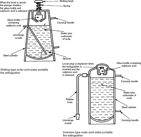
Sand and water buckets are no longer acceptable as a first-aid fire treatment facility. Purpose-provided extinguishers are now commonplace in public and commercial buildings. Under the obligations of the Health and Safety at Work, etc. Act, employees are required to undertake a briefing on the use and selection of fire extinguishers. Water in pressurised cylinders may be used for carbonaceous fires and these are commonly deployed in offices, schools, hotels, etc. The portable soda-acid extinguisher has a small glass container of sulphuric acid. This is released into the water cylinder when a knob is struck. The acid mixes with the water which contains carbonate of soda to create a chemical reaction producing carbon dioxide gas. The gas pressurises the cylinder to displace water from the nozzle. The inversion type of extinguisher operates on the same chemical principle.
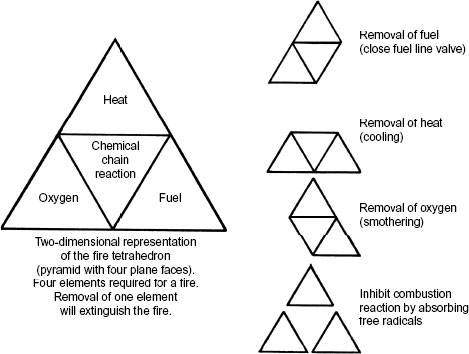
Although water is a very good cooling agent, it is inappropriate for some types of fire. It is immiscible with oils and is a conductor of electricity. Therefore, the alternative approach of breaking the fire tetrahedron by depleting the oxygen supply can be achieved by smothering a fire with foam. Foam is suitable for gas or liquid fires.
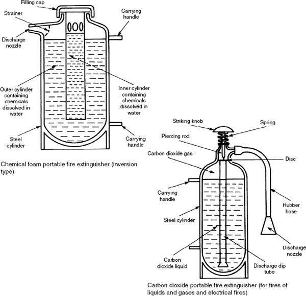
Chemical foam type of extinguisher – foam is formed by chemical reaction between sodium bicarbonate and aluminium sulphate dissolved in water in the presence of a foaming agent. When the extinguisher is inverted the chemicals are mixed to create foam under pressure which is forced out of the nozzle.
Carbon dioxide extinguisher – carbon dioxide is pressurised as a liquid inside a cylinder. Striking a knob at the top of the cylinder pierces a disc to release the carbon dioxide which converts to a gas as it depressurises through the extinguisher nozzle.
Carbon monoxide (CO) gas is colourless, invisible, tasteless and odourless. Where allowed to accumulate it cannot be detected by human perception or senses. With sufficient exposure it can be deadly, hence its common reference as the ‘silent killer’. It is the primary cause of death by accidental poisoning in the UK, with estimates in excess of 20 persons per year and some 200 others seriously injured. About half of these incidents are attributed to faulty fuel-burning appliances, either incorrectly serviced or improperly installed. It is not easy to determine the total numbers of people affected, as the symptoms and characteristics can be similar to other medical disorders.
Symptoms – limited exposure to carbon monoxide poisoning is often unrecognised. The symptoms can be superficially very similar to that of influenza and food poisoning, leading to wrong diagnosis in the absence of blood tests.
Slight exposure – headache, nausea, vomiting, fatigue and aching limbs.
Greater exposure – throbbing headache, drowsiness, confusion and increased heart rate.
High level of exposure – unconsciousness, collapse, convulsions, cardio-respiratory failure, deep coma and ultimately death.
Note: Exposure, whether in small ongoing doses or occasional concentrated amounts, can result in permanent disability due to neurological damage and functional loss of brain cells.
Effect on the human body – the body’s ability to transport oxygen to vital organs is impaired when exposed to carbon monoxide. Carbon monoxide bonds with the haemoglobin in blood to gradually replace oxygen. This prevents the uptake of oxygen into the blood and the body begins to suffocate.
Most at risk –
Those at home for long periods, i.e. the house-bound.
Elderly and infirm, particularly those with heart/respiratory problems.
Pregnant women, children and pets.
Appliances – all those fuelled from fossil resources, including wood, coal, charcoal, oil, gas (inc. LPG) and paraffin. Carbon monoxide is a product of incomplete combustion. To function efficiently, heat-producing appliances must have adequate oxygen supplied through purpose-made air vents to achieve complete combustion of fuel. The products of combustion should be exhausted safely through a correctly sized, undamaged and unobstructed flue system. The position of flue outlets and the location of outside appliances is important as carbon monoxide can permeate the structure.
Modern houses are extremely well sealed which may be advantageous in preventing the ingress of flue gases. However, unlike older houses, there is less natural air leakage through the structure to aid fuel combustion and to dilute escaping gases. Whatever, there is no safe option other than regular servicing and maintenance for all heat-producing appliances. CO detectors are an essential safety installation for all dwellings and other buildings containing combustion appliances.
Registered social landlords have a duty of care for their tenants safety. This includes provision for protection against CO poisoning. E.g. registered student accommodation.
Types of detector/alarm – mains or battery powered. Audible, also available with a visual facility for people with hearing difficulties. Size and appearance resembles a domestic smoke alarm, but the sensor inside the unit differs, being any of the following:
An electrochemical type of fuel cell that is energised in the presence of CO.
Biomimetic – a synthetic haemoglobin that darkens in the presence of CO. The colour change activates a light cell.
Semiconductor – an electric circuit of thin tin oxide wires on a ceramic insulator. Presence of CO reduces the electrical resistance, allowing greater current flow to activate the alarm.
The positioning and number of carbon monoxide detectors depends on the layout of rooms. Several individual battery-powered detectors/ alarms is acceptable, but it is preferable to have a system or network of hard-wired mains-powered interlinked detectors.
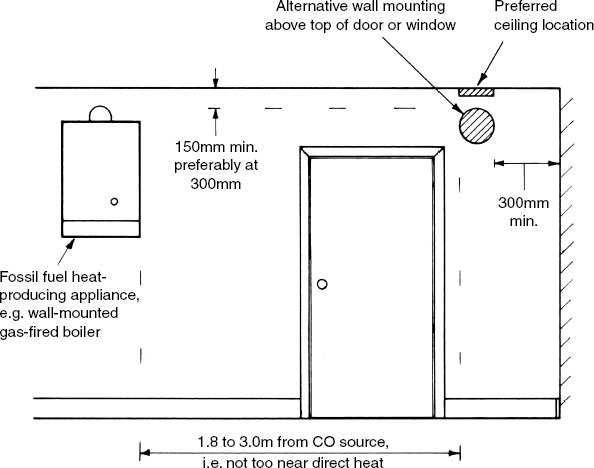
Location –
In any room containing a fuel-burning appliance.
Bedrooms, positioned at pillow height.
Remote rooms, 1.5 to 2.0m above floor level.
Room adjacent to a dedicated boiler room.
In bed-sits, close to sleeping area and away from cooking appliance.
Not in bathrooms or shower rooms.
Positioning –
Ref. BS EN 50291-1: Electrical apparatus for the detection of carbon monoxide in domestic premises. Test methods and performance requirements.