
15 Accommodation for Building Services

Ducts for Engineering Services
Medium and Large Vertical Ducts
Medium and Large Horizontal Ducts
Separate trenches for individual services is cost ineffective. A single excavation with sufficient space to accommodate several pipes and cables is less disruptive, less exposed to damage and uses plant and labour more effectively. Contact with the local public utilities suppliers to coordinate their facilities as a preliminary element of the work programme enables installations to be undertaken and backfilled without later disruption. Supplies can then be used during construction.
Separation between different services is necessary for maintenance accessibility. Plastic-piped water supplies should be laid at least 350mm from gas pipes, to prevent possible contamination from gas leakage. In addition, plastic-piped water services must not be located in the vicinity of hydrocarbon (oil, petrol and creosote) storage, as leakage of these can cause deterioration of the pipe.
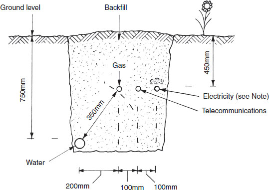
Note: High-voltage electricity cables to be protected, usually with clayware or concrete capping stones.
Common services/utilities trench, minimum dimensions given.
Ducts for Engineering Services – Below Ground
Before installing ducts for the entry of services into a building, it is essential to ascertain the location of pipes and cables provided by the public utilities companies. Thereafter, the shortest, most practicable and most economic route can be planned. For flexible pipes and cables, a purpose-made plastic pipe duct and bend is used to protect the service at its point of entering a building. Ducts are sealed at the ends with a plastic filler and sealant, otherwise subsoil, ground water and possibly vermin will access the duct. If the duct is blocked, its effectiveness to absorb differential settlement between the building and incoming service will be impaired. The details below show provision for water supply. For gas and electricity intakes, see pages 445 and 499 respectively.

Ducts for Engineering Services – Above Ground
Water, gas and electrical services can be easily accommodated horizontally below timber and other wood product boarding by securing pipes and cables to the side of support joists. With solid flooring a skirting or floor duct may be used. These are purpose made by the site joiner or purchased as standard manufactured items to be secured to the room periphery or set in concrete floors. Vertical services may be housed in a surface duct or a recess chased into the wall. A chase is only acceptable if its depth does not affect the structural strength of the wall. Also, depending on location, the potential to reduce the wall’s thermal and sound insulation properties must be considered. Water installations and fittings must not be embedded in a wall or floor. They can be placed in ducts that are reasonably accessible by the removal of superficial finishes such as carpeting and tiling. Gas pipework should also be in purpose-made ducts, at least 25mm from any other service and 50mm from an electrical supply.

Notching and Holing Timber Joists
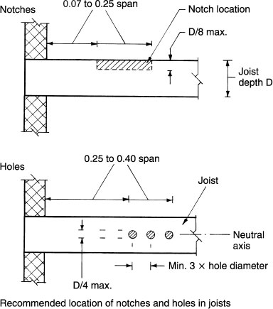
Services installations may be concealed within the structure by an access board or panel. The structure and its components should not be damaged to accommodate services but some nominal holing and notching will be unavoidable and is acceptable. Wherever possible, pipes and cables should run parallel and be secured to the sides of joists. Where services are at right-angles to joists the optimum location is through a hole in the joist centre or neutral axis. This is where compressive and tensile stresses are minimal. Holing is convenient for cables and flexible pipes, but notching the tops of joists is the only practical means for accommodating rigid pipes. Notching will reduce the strength of joists; therefore where services are apparent, the structural designer should be informed and the joists oversized accordingly.
Restrictions and guidance – the principal areas to avoid notching and holing of joists are mid-span (maximum bending) and close to supports (maximum shear).
Notches not greater than 0·125 × joist depth.
Notches located between 0·07 and 0·25 times the span, from support.
Hole diameter, maximum of 0·25 × joist depth.
Holes a minimum of 3 × diameter apart.
Holes located between 0·25 and 0·40 times the span, from support.
Notching and Holing Fabricated Timber Joists
Manufactured timber joists/beams are frequently used in house construction as an economical alternative to standard timber sections. Notches should be avoided, but holing is acceptable as shown by the following guidance –
Laminated veneer beam –

Parallel strand beam –

Engineered I beam –

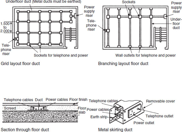
A grid distribution of floor ducting is appropriate in open plan offices and shops where there is an absence of internal walls for power and telecommunications sockets. It is also useful in offices designed with demountable partitioning where room layout is subject to changes. Sockets are surface mounted in the floor with a hinged cover plate to protect them when not in use. The disruption to the structure is minimal as the ducts can be set in the screed, eliminating the need for long lengths of trailing cables to remote workstations. For partitioned rooms, a branching duct layout may be preferred. The branches can terminate at sockets near to the wall or extend into wall sockets. Where power supplies run parallel with telecommunications cables in shared ducts, the services must be segregated and clearly defined. For some buildings, proprietary metal, plastic or laminated plywood skirting ducts may be used. These usually have socket outlets at fixed intervals.
See also page 654.
Medium and Large Vertical Ducts
The purpose of a service duct is to conceal the services without restricting access for inspection, repair and alterations. A duct also helps to reduce noise and protect the services from damage. When designing a service duct, the transmission of noise, possible buildup of heat in the enclosure and accessibility to the services must be considered. The number of ducts required will depend on the variation in services, the need for segregation and location of equipment served. Vertical ducts usually extend the full height of a building which is an important factor when considering the potential for spread of fire. The duct must be constructed as a protected shaft and form a complete barrier to fire between the different compartments it passes. This will require construction of at least 60 minutes’ fire resistance with access doors at least half the structural fire resistance.

Refs. BS 8313: Code of practice for accommodation of building services in ducts.
Building Regulations, Approved Document B3: Internal fire spread (structure).
Medium and Large Horizontal Ducts
Floor trenches are usually fitted with continuous covers. Crawl-ways generally have access covers of minimum 600mm dimension, provided at convenient intervals. A crawl-way should be wide enough to allow a clear working space of at least 700mm and have a minimum headroom of at least 1m. Continuous trench covers may be of timber, stone, reinforced concrete, metal or a metal tray filled to match the floor finish. The covers should be light enough to be raised by one person, or, at most, two. Sockets for lifting handles should be incorporated in the covers. In external situations, the cover slabs (usually of stone or concrete) can be bedded and joined together with a weak cement mortar. If timber or similar covers are used to match a floor finish, they should be fixed with brass cups and countersunk brass screws. A trench has an internal depth of less than 1m. In internal situations where ducts cross the line of fire compartment walls, a fire barrier must be provided within the void and the services suitably fire stopped (see pages 434 and 661).
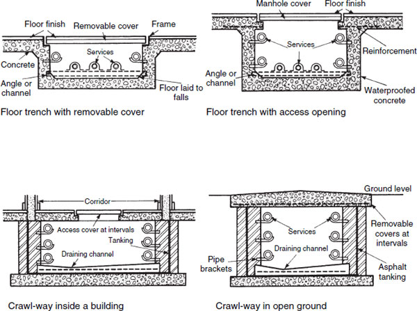
Access to a subway will normally be from a plant room, control room or a basement. Additional access from the surface should also be provided at convenient junctions and direction changes. See page 325 for provision of wall step irons. The design and construction of these ducts should adequately withstand the imposed loads and pressures that will occur under extreme working conditions. They should be watertight and where used internally have adequate resistance to fire. Ducts housing boiler or control room services must be provided with a self-closing fire door at the entry. Ventilation to atmosphere is essential and a shallow drainage channel should convey ground water leakage and pipe drainage residue to a pumped sump or a gully connection to a drain.

Penetration of Fire Structure by Pipes
The effect of fire spreading through the voids associated with internal pipework penetrating fire-resistant walls and floors can be considered in four areas:
Addition of fuel to the total fire load.
Production of toxic gases and smoke.
Risk of fire spread along the pipework.
Reduction in fire resistance of the building elements penetrated.
Guidance in Approved Document B3 to the Building Regulations is mostly applied to sanitation pipework penetrating the structure, but could affect other services, particularly in large buildings. Acceptable sleeving and sealing methods for uPVC discharge pipes are shown on page 434. Non-combustible pipe materials up to 160mm nominal i.d. (excluding lead, aluminium, aluminium alloys, uPVC and fibre cement) may have the structural opening around the pipe fire stopped with cement mortar, gypsum plaster or other acceptable non-combustible material. Where the pipe material is one of those listed in parentheses, and it penetrates a wall separating dwellings or a compartment wall or floor between flats, the discharge stack is limited to 160mm nominal i.d. and branch pipes limited to 110mm nominal i.d., provided the system they are part of is enclosed as shown.
* Any other materials (e.g. polypropylene) have a maximum nominal i.d. of 40mm.

Ref. Building Regulations, Approved Document B3: Internal fire spread (structure).
Raised flooring provides discrete housing for the huge volumes of data and telecommunications cabling, electrical power cables, pipes, ventilation ducts and other services associated with modern buildings. Proprietary raised floors use standard 600mm square interchangeable decking panels, suspended from each corner on adjustable pedestals. These are produced in a variety of heights to suit individual applications, but most range between 100mm and 600mm. Panels are generally produced from wood particle board and have a galvanised steel casing or overwrap to enhance strength and provide fire resistance. Applied finishes vary to suit application, e.g. carpet, wood veneer, vinyl, etc. Pedestals are screw-threaded steel or polypropylene legs, connected to a panel support plate and a base plate. The void between structural floor and raised panels will require fire stopping at specific intervals to retain the integrity of compartmentation.

Ref. BS EN 12825: Raised access floors.
Building Regulations, Approved Document B: Fire safety, Vol. 2, Part B3, Section 9: Concealed spaces (cavities).
A suspended ceiling contributes to the fire resistance of a structural floor. The extent of contribution can be determined by reference to Appendix A in Approved Document B of the Building Regulations. An additional purpose for a suspended ceiling is to accommodate and conceal building services, which is primarily the function of a false ceiling.
False ceiling systems may be constructed in situ from timber or metal framing. A grid or lattice support system is produced to accommodate loose-fit ceiling tiles of plasterboard, particle board or composites. Proprietary systems have also become established. These are a specialised product, usually provided by the manufacturer on a design and installation basis. Most comprise a simple metal framing with interconnecting panel trays. As with raised flooring, the possibility of fire spreading through the void must be prevented. Fire stopping is necessary at appropriate intervals as determined in Approved Document B3 to the Building Regulations.

Refs. BS EN 13964: Suspended ceilings. Requirements and test methods. Building Regulations, Approved Document B: Fire safety, Vol. 2, Part B3, Section 9: Concealed spaces (cavities).