
Chapter 9. Implementing a DS Platform
In Chapter 1, “Introduction to Distributed Platforms,” we introduced the concept of a distributed services platform. Figure 1-1 (reproduced here as Figure 9-1) depicts a high-level view of the components required to implement a distributed services platform. Key components are the distributed services nodes (DSNs) placed in servers, switches, and appliances that need to be managed by a policy manager.

FIGURE 9-1 A Distributed Services Platform
In this chapter, we detail the goal of a distributed services platform. We also describe the constraints that derive from the server architectures (for example, virtual machines versus bare-metal servers) and from the need to fit into existing installation or the possibility of designing the architecture from scratch. We compare the Enterprise data center architecture with one of the public clouds, and we analyze where to best locate the DSNs.
9.1 Analyzing the Goals for a Distributed Services Platform
Let’s first analyze the goals for a distributed services platform. In previous chapters we saw that we want to distribute services at the periphery of the network by installing DSNs as close as possible to the applications, to make the network as simple as possible, and to adopt for services the same scale-out model adopted for computing. Moreover, we want to be able to chain together multiple services inside the DSN, avoiding useless network crossing.
In this section, we analyze more specific requirements for this distributed services architecture. Let’s first analyze the goals for a distributed services platform.
9.1.1 Services Everywhere
Today, one of the complexities of service implementation is that different services are implemented by various appliances in different parts of the network. Because several services need to be chained together to build a complete application, this results in unnecessary complexity and packets having to travel multiple times over the network with various overlay encapsulations—a phenomenon known as tromboning (see section 2.7.1).
An ideal distributed services platform makes all the services available in all the DSNs so that service chaining can happen inside the DSN and does not require redirecting packets between boxes to chain multiple services, such as a firewall and load balancing.
A real distributed services platform approximates the ideal one by taking into consideration several other aspects described in the remainder of this chapter.
9.1.2 Scaling
With the introduction of cloud architectures, scaling has become a primary requirement because of multi-tenancy. A cloud provider, be it private, public, or hybrid, needs to run IP routing for the underlying network and all the overlay networks associated with each tenant. Moreover, protection between different tenants is put in place in terms of Access Control Lists (ACLs), even if each tenant does not explicitly require it. Also, if each tenant uses a moderate number of routes and ACLs (let’s say up to one thousand), a DSN located in a server with 100 tenants requires the simultaneous presence of 100,000 routes and 100,000 ACLs for both IPv4 and IPv6. The situation can be more extreme if the DSN is located in a switch or an appliance that processes the traffic aggregated by, let’s say, 40 servers: 4 million routes and ACLs can be required in this case. The same is true for the scaling of other services such as firewall, load balancing, and network address translation (NAT). In this case, to support stateful services the DSN needs to keep a flow table that can accommodate tens of millions of flows in addition to the number of routes and rules quoted previously. A similar consideration applies to encryption, both in terms of the number of keys and the number of encrypted tunnels, with the additional complication that keys need to be stored in a secure place, such as a hardware security module (HSM) (see section 5.8).
9.1.3 Speed
Speed requirements vary between enterprises and cloud providers. At the time of writing, most enterprise servers are connected at 10 Gbps, and the transition to 25 Gbps is starting. Cloud provider servers are mostly 40 Gbps to 50 Gbps, moving to 100 Gbps. Backbone links vary from 100 Gbps to 400 Gbps.
Let’s consider in greater detail what 100 Gbps means. With an average packet length of approximately 400 bytes, a 100-Gbps DSN needs to be capable of processing about 30 million packets/second. This processing must at least include the chaining of the most common services; for example, receiving an encrypted overlay tunnel, decrypting it and decapsulating it, applying firewall rules, routing the packets, and delivering them to the layer 2 destination. We will see in the next chapter that a performance of this order of magnitude strictly limits the architectural choices at the hardware level. Another consideration is that an average flow length is approximately 1 Mbit, and this implies that at 100 Gbps there are 100,000 new flows every second. Stateful flow tables and all the telemetry apparatus must be designed to be capable of supporting this number of new flows per second. Once again, this can be challenging from a hardware perspective.
9.1.4 Low Latency
The need to provide services with low latency is essential. At today’s 100 Gbps transmission speeds, a 1500-byte Ethernet frame has a serialization delay of 120 nanoseconds. The speed of light in fiber is 200,000 Km/s; that is, a 100 meters (328 feet) link has a delay of 500 nanoseconds. Overall, the delay associated with transmission should be less than 2 microseconds. The majority of the delay is associated with packet processing related to services and routing/bridging. When multiple services need to be applied to a packet, and the services are implemented in different appliances, the delay is caused by the packet having to cross the network artificially multiple times to chain the services and by the bottleneck caused by tromboning into the appliances.
Of course, the lower the latency is, the better the overall performance will be but, in practice, a good goal is to try to implement a service chain with a latency below 10 microseconds.
9.1.5 Low Jitter
In the previous section, we discussed the importance of limiting “average” delay, but different packets experience different delays. This delay variation is called jitter, and it is as crucial as delay, especially for applications that require real-time communications such as IP telephony and video conferencing. If jitter is high, packets can be reordered or dropped, and this shows up as a malfunction at the application layer.
The makers of network equipment have been aware of this issue for a long time, and their hardware designs limit jitter as much as possible and don’t reorder frames. Frame reordering is terrible even for a protocol like TCP that will associate packet reordering with congestion and, therefore, reduce its throughput.
The same level of awareness is not present in software implementation. Techniques discussed in section 6.3 such as interrupt moderation and coalescing sacrifice jitter while trying to increase overall throughput. Packet processing in software requires activities to be scheduled by the operating system, whose goal is to create fairness among all the processes, not to minimize jitter. It is not uncommon in software implementation to see jitter exceeding 100 microseconds, and this becomes the dominant factor of poor performance.
9.1.6 Minimal CPU Load
In the previous chapter, we have seen that single-thread performance is now growing very slowly and that CPU cycles must be saved for user applications and not used for distributed services. An ideal distributed services platform has a zero footprint in the host, allowing all the CPU cycles to be dedicated to user applications.
An additional consideration is that general-purpose CPUs are not designed for packet processing, and their hardware architecture is not a good fit for operations commonly used in packet processing.
For this reason, a software implementation of a DSN, even though it is extraordinarily flexible and potentially scalable with a lot of memory, has low performance, high delay, and high jitter.
The term offloading is often used to indicate attempts to move part of the processing to a domain-specific hardware structure, but offloading still leaves a footprint on the host software that can be extremely significant.
It is the author’s opinion that a successful DSN implementation should be self-contained and have no footprint on the server software. This provides greater security, better control of noisy neighbors, and allows separate administration domains.
“No footprint” on the server software is also a mandatory requirement for bare-metal servers, where no assumption can be made about the software run on the server.
9.1.7 Observability and Troubleshooting Capability
With billions of packets being exchanged every second over a network, it is challenging to troubleshoot when something goes wrong. The historical approach has been to have a management station that pulls information from network devices, using a protocol such as SNMP, and SSH to connect to the CLI of network devices. This approach is now inadequate.
A more modern approach is telemetry-based and includes the following parts:
Measure and collect in the data path: With a link at 100 Gbps passing 30 million packets per second, measurement and collection cannot rely on a management processor outside the data path; they must be built as an integral part of the data path from day one.
Timestamp accurately: The data path needs to timestamp packets with a very accurate timestamp; let’s remind ourselves that at 100 Gbps a packet lasts less than 500 nanoseconds, and without a timestamp synchronized network-wide with tens of nanosecond precision, it is impossible to understand what happened first. The Precision Time Protocol (PTP) [1] is the standard solution to this problem, but it is complicated to set up. A more modern approach [2] developed at Stanford University and at Google is looking promising.
Stream out: After telemetry is collected and timestamped, it needs to be streamed out toward a collection station. Due to the sheer volume of data, filtering may be used to stream out only data that is associated with potential issues; for example, when predefined thresholds are exceeded.
Collect: A telemetry collection station must store all this information, typically in a time-series database [3] where it can be retrieved and analyzed later on.
Correlate and analyze: This step is the last one, and it correlates all the information to help the network manager understand what is happening in the network and identify possible bottlenecks and malfunctions.
9.1.8 Manageability
The best distributed services platform will fall short without excellent management. It must be model-based; that is, all the management tools, interfaces, and protocols must be derived from a common model. Commonly used modeling languages are Swagger [4], OpenAPI [5], and Yang [6]. From them, it is possible to generate in an algorithmic way a RESTful API [7] and gRPC [8]/protobuff [9] (see sections 3.4.1 and 3.4.2). The model must come first, APIs second, and all the remaining tools such as CLI, SNMP, and so on must be layered over the APIs.
Using a microservices architecture to build a distributed management system can offer better scale, composability, and high availability.
The scope of the management system is to define policies in a central location and enact them on the DSNs. In a simple situation, all policies can be pushed everywhere, but with the growth of the number of DSNs, partitioning policies may become a necessity, both at the policy definition and enforcement level. For example, policies that are specific to one site can be defined locally and do not need to be propagated to other locations. For this reason, it is essential that the management system supports the concept of “federation.” In a federated system, multiple policy managers work together to enforce a combination of global and local policies.
9.1.9 Host Mode versus Network Mode
The next management consideration is where is the entry point into the DSN for the management protocol. Two main modes exist: host mode and network mode.
In host mode, the DSN is managed through the PCIe interface of the NIC (Network Interface Card). This mode is not the most desirable for the DSN, because a compromised host may compromise the DSN and nullify its security features.
A more desirable mode is the network mode in which the DSN is managed through a secure network connection—either in-band or out-of-band—by a trusted policy manager. This mode is more secure and in general all implementations of DSNs can use it, even the ones that do not rely on the presence of a PCIe interface.
9.1.10 PCIe Firewall
To increase security, a NIC must not only support the previously described network mode but must also implement a PCIe firewall, a hardware structure similar to a Memory Management Unit (MMU) that controls the access to internal NIC resources through the PCIe bus. This additional security measure is particularly relevant in the presence of SR-IOV to guarantee that each vNIC in a VM accesses only the resources associated with its virtual function (VF; see section 8.4). With this protection in place, rogue software running on a compromised VM cannot access the network resources of other VMs.
9.2 Understanding Constraints
In designing a distributed services platform, we need to keep considering not only the goals listed in the previous sections, but also the constraints listed in the following subsections. The combination of the two will often result in the decision of where to best locate the DSN.
9.2.1 Virtualized versus Bare-metal Servers
Usually, virtualized servers are provisioned to users in terms of VMs. The virtualization/cloud provider has full control over the hypervisor, including the vSwitch that can be used to host a DSN. Also, a VM on the same server may be used to run distributed services management and control protocols. Some of these features may also be offloaded to hardware, minimizing the footprint on the server CPUs. One may question the overall performance of a DSN implemented in software, but today this is a deployed solution.
The situation is different in bare-metal servers; that is, in servers that are provisioned without making any assumption about the operating system or applications that will be running on them. In bare-metal servers, the server provider cannot assume anything, including the presence of a hypervisor, and cannot run a DSN or a service VM on the server. In this case, the software implementation of a DSN is unfeasible, and it is necessary to provide distributed services with a DSN that has a zero footprint on the host; for example, in a NIC or a switch.
9.2.2 Greenfield versus Brownfield Deployment
A standard definition of the term greenfield project is, “a project that lacks any constraints imposed by prior work.”
In a greenfield installation of a cloud infrastructure, each component is chosen carefully, and it is possible, for example, to install the more desirable server configuration, including a NIC capable of supporting a DSN. In general, a greenfield installation offers the highest level of flexibility on where to locate the DSNs.
When servers are deployed in production, they become brownfield, and their hardware configuration is usually kept unchanged until the server is decommissioned. Therefore, if a server was installed with a NIC that is incapable of supporting a DSN, the NIC is not upgraded.
In brownfield projects, the retrofitting of a distributed services platform is done by adding or replacing network boxes with new ones capable of supporting DSNs.
9.2.3 The Drivers
Software drivers for NIC cards need to be installed in the kernel of the operating system or the hypervisor. Although all NIC vendors provide drivers for their NICs for a variety of operating systems and hypervisors, sometimes users prefer to install NIC cards for which the driver is already present in the distribution of the operating system and does not need to be installed manually.
To be included in an operating system distribution—that is, to be an in-box driver—a driver needs to be “upstreamed” (i.e., a driver is merged and becomes part of a standard operating system distribution), a process that may easily take one year. Usually, upstreamed drivers are available only for the latest versions of the OS. This is an issue with legacy bare-metal servers that run applications certified with old or customized kernels.
The availability of drivers may limit the choice of which NIC to install and, therefore, where to place the DSNs.
9.2.4 PCIe-only Services
In Chapter 4, “Network Virtualization Services,” and Chapter 5, “Security Services,” we analyzed several network and security services that conceptually can be located anywhere in the cloud or data center network. Placing them as closely as possible to the user applications is always the best choice, but because these distributed services work on network packets, they can be placed outside the servers.
A different situation exists for the services described in Chapter 6, “Distributed Storage and RDMA Services”; namely RDMA and storage. These services are strictly coupled with a server PCIe interface, and, therefore, should be implemented in a NIC. For example, RDMA accesses the memory of the server through PCIe without the intervention of the server CPU, which is not possible without a direct PCIe connection.
The situation is slightly more flexible for storage services, in which some value-added features, such as encryption and compression, are not strictly tied to the PCIe interface.
In general, for PCI-based services, the optimal location of the DSN is in the NIC.
Although security can be implemented in multiple places, it is ideal when implemented in the NIC: the traffic can be encrypted and decrypted at the edge of the network (or as close as possible to the application), so no plain text is exposed at any portion of the network.
9.2.5 Power Budget
The power budget is probably the single most significant constraint for a DSN. The next chapter presents a few hardware alternatives for implementing a DSN. Power consumption and the associated cooling considerations are critical parameters for comparing them.
Chapter 8, “NIC Evolution,” contains a discussion of the power budget for NICs. In a standard PCIe slot, power must be limited to 25 watts, and some adapters use two adjacent PCIe slots to be able to draw between 25 and 50 watts, but this is a suboptimal solution, not available in the case of other form factors, such as the Open Compute Project (OCP).
9.3 Determining the Target User
A distributed services platform has applicability for different classes of users: cloud providers, enterprises, and service providers. Their use cases and requirements have significant overlaps, but also differences, as discussed in the following sections.
9.3.1 Enterprise Data Centers
Enterprise data centers, while potentially extremely large, don’t have the level of scale of public clouds. A distributed services platform is appealing to them for the following reasons:
It increases the East-West security by deploying more firewalling and opportunistic encryption everywhere (if encryption is a free service, let’s use it).
It simplifies the network infrastructure by eliminating traffic trombone and the associated overlay encapsulation.
A cloud-like infrastructure plays well with public clouds and can lend itself to become a hybrid cloud.
Enterprises are interested in a turnkey solution that includes a policy manager and all the telemetry tools required for troubleshooting and performance analysis.
It eliminates the need for costly discrete appliances such as the firewall and load balancer to achieve a lower total cost of ownership. This requirement is real in large data centers, but it is extreme in small satellite data centers, where the cost of discrete appliances is shared across a limited number of servers and, therefore, becomes the dominating factor.
The amount of traffic an enterprise solution should support, although high, is not comparable to that of public cloud providers.
9.3.2 Cloud Providers and Service Providers
Cloud and service providers have scaling issues that are second to none. They need a solution that pushes the boundaries in terms of the number of routes, ACLs, flows, firewall rules, security association, and so on.
They are not interested in a turnkey solution because they have huge investments in the management infrastructures. They require DSNs that are easy to integrate through the availability of programmatic APIs, such as REST API and gRPC.
Often these APIs are not enough for them as they want to be able to port their management agent software directly on the DSN and interface it with a low-level hardware API for deeper integration. For this reason, the availability on the DSN of a standard processor that runs a Linux OS distribution is desirable.
Once again, telemetry is critical, and cloud providers already have some telemetry infrastructure in place where they want to feed the telemetry data coming from the DSNs.
9.4 Understanding DSN Implementations
This section describes five possible ways to implement a DSN, starting from the one “inside” the server and moving into the network progressively farther away from the server.
9.4.1 DSN in Software
One of the possibilities is to implement the DSN in software on the main server CPU. At the time of writing this option is deployed in some enterprise data centers, but it doesn’t scale for cloud providers.
The software solution requires the presence of a hypervisor and a virtual switch, a non-starter for bare-metal servers where the entire server is dedicated to a user, and there is no place to run the DSN.
Different solutions exist depending on whether the hypervisor is public domain or proprietary.
For example, for a proprietary hypervisor like ESXi, VMware sells a software solution called NSX that includes switching, routing, firewalling, and microsegmentation, with the availability of SSL and IPsec VPNs for site-to-site communications.
For open-source hypervisors, it is possible to extend the functionality of the virtual switch to implement a DSN, but this can get complicated quickly, often requiring programming and debugging in the kernel space.
Most of the available solutions move the programming into userspace, implementing the DSN in software in a virtual machine or container. Of course, these solutions rely on the main server CPU to run the DSN.
Figure 9-2 shows a possible arrangement. A standard NIC sends all the incoming packets to a virtual machine or to a container that implements the DSN and, after the appropriate processing, the packets are delivered to the final destination (another virtual machine or container). Similar processing happens on the reverse path.

FIGURE 9-2 Server with a Classical NIC
Offload techniques have been attempted to improve performance, but the results are not great, especially in terms of latency and jitter.
The software option can be used in greenfield and brownfield deployments for both VMs and containers, and it does protect VMs and containers on the same server from each other but, from a security perspective, if the server is compromised, the DSN is also potentially compromised.
The following summarizes the characteristics of this solution for comparison with the other four proposed in this chapter:
Applicability: Greenfield and brownfield
Bare-metal: No support
Performance: Low
Footprint on the server: Very high
Support for RDMA and storage: Dependent on the server NIC
Requires extra port on ToR: No
Requires a distributed services ToR: No
Security compromised if server compromised: Yes
9.4.2 DSN Adapter
Locating the DSN in domain-specific hardware inside the NIC is an optimal solution for high- performance servers that run VMs and containers, especially in a greenfield environment.
An example of this solution is the Annapurna Nitro card from AWS [10].
This solution does not require the presence of a hypervisor or a software virtual switch and, therefore, can be used for bare-metal servers, provided that NIC drivers are available for the particular OS installed on the bare-metal server.
Figure 9-3 shows a possible arrangement in which the NIC contains a fully self-sufficient DSN, including the switch, and uses SR-IOV toward the virtual machines.
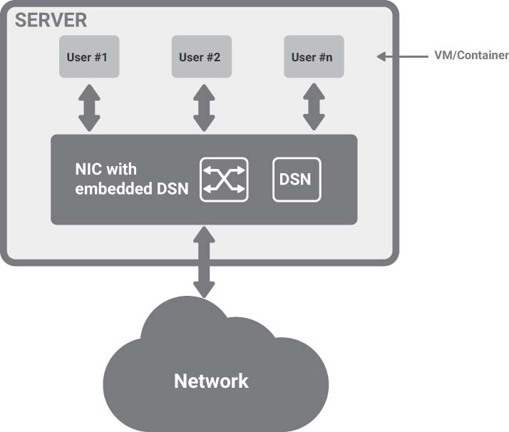
FIGURE 9-3 Server with a DSN-capable NIC
This option can protect VMs and containers on the same server from each other and can also implement advanced features such as PCIe firewall. From a security perspective, if the server is compromised, the DSN maintains its integrity and continues to provide protection.
The following summarizes the characteristics of this solution for comparison with the other four proposed in this chapter:
Applicability: Greenfield
Bare-metal: Good support, if drivers are available
Performance: Highest
Footprint on the server: Minimal to nonexistent
Support for RDMA and storage: Yes
Requires extra port on ToR: No
Requires a distributed services ToR: No
Security compromised if server compromised: No
9.4.3 DSN Bump-in-the-Wire
The so-called bump-in-the-wire is an option for high-performance bare-metal servers both in greenfield or brownfield environments. It is very similar to the previous one, but it removes the dependency on the availability of NIC drivers. The server has two PCIe cards:
A NIC card that can be a ubiquitous model with excellent driver availability.
A DSN card that is a bump-in-the-wire between the NIC and the Top of Rack (ToR) and implements all the distributed services.
DSN cards can be just “power-sucking aliens” on the server PCIe. Figure 9-4 shows a possible arrangement with the two cards.

FIGURE 9-4 Bump-in-the-Wire
As in the previous case, if from a security perspective the server is compromised, the DSN maintains its integrity and continues to provide protection.
The following summarizes the characteristics of this solution for comparison with the other four proposed in this chapter:
Applicability: Greenfield and possibly brownfield
Bare-metal: Optimal support, independent of driver availability
Performance: Highest
Footprint on the server: Minimal to nonexistent
Support for RDMA and Storage: Yes
Requires extra port on ToR: No
Requires a distributed services ToR: No
Security compromised if server compromised: No
9.4.4 DSN in Switch
In the DSN in software and DS adapter solutions, the DSN was in the server; in the bump-in-the-wire solution, it was on the wire between the server and the ToR; in this solution, it is in the ToR. Conceptually, this solution is identical to bump-in-the-wire because the only difference is the place where the DSN is connected on the wire. There are two technical differences, however:
The ToR provides the power and the cooling of the DSN instead of the server.
The PCIe interface is not connected, and therefore, there is no support for RDMA and storage service.
This solution consolidates the DSN and the ToR switch (also known as a leaf switch) in a single box. Multiple DSN ASICs may be present in the DS switch and shared among the servers in the rack. This solution reduces the total cost of ownership, especially for enterprise applications, where it may be difficult to justify a dedicated DSN for each server because the volume of traffic is not as high as in the public cloud.
Figure 9-5 shows a possible arrangement with a DS switch built with a merchant switch silicon ASIC and four DSN ASICs.

FIGURE 9-5 DSN in Switch
Please note that from a management and telemetry perspective, nothing changes; there is still a policy manager that can work in any of these solutions and should support a mix of different implementations in the same network.
To implement security across VMs and containers in the same server, the server NIC should deploy SR-IOV and send all the traffic to the DS switch. Each VM or container can be tagged explicitly; for example, by adding a VLAN tag, or it can be tagged implicitly by its source MAC address.
Please note that this solution does not require using VXLAN encapsulation because the DSNs in the ToR are in the same layer 2 domain as the servers.
The following summarizes the characteristics of this solution for comparison with the other four proposed in this chapter:
Applicability: Brownfield and greenfield
Bare-metal: Optimal support, independent of driver availability
Performance: High
Footprint on the server: Minimal to nonexistent
Support for RDMA and storage: No
Requires extra port on ToR: No
Requires a distributed services ToR: Yes
Security compromised if server compromised: No
9.4.5 DSNs in an Appliance
An appliance connected through 100 Gbps Ethernet links to the ToR switch contains the DSNs. This solution is a variation of the previous one but targeted more toward the brownfield deployment where there is no desire to replace the ToR switch, and the ToR switch has extra Ethernet ports available. It is depicted in Figure 9-6.

FIGURE 9-6 DSNs in an Appliance
Summarizing the characteristics of this solution and comparing it with the other four proposed in this chapter:
Applicability: Brownfield and greenfield
Bare-metal: Optimal support, independent of driver availability
Performance: Intermediate
Footprint on the server: Minimal to nonexistent
Support for RDMA and storage: No
Requires extra port on ToR: Yes
Requires a distributed services ToR: No
Security compromised if server compromised: No
9.5 Summary
In this chapter, we have analyzed the goals, constraints, target users, and possible implementation of a distributed services platform.
We have shown that the DSN may be implemented either in software on the main server CPU or in hardware. In the second case, we assumed that the DSN hardware could be hosted on a NIC, as a bump-in-the-wire, in a ToR switch, or an appliance connected to the ToR switch.
Table 9-1 summarizes the five possible ways to implement a DSN.
TABLE 9-1 Possible Ways for DSN Implementation
|
DSN in Software |
DSN Adapter |
DSN Bump-in-the-Wire |
DSN in Switch |
DSN in an Appliance |
Applicability |
Greenfield and Brownfield |
Greenfield |
Greenfield and possibly Brownfield |
Brownfield and Greenfield |
Brownfield and Greenfield |
Bare-metal |
No support |
Good support, if drivers are available |
Optimal support, independent of driver availability |
Optimal support, independent of driver availability |
Optimal support, independent of driver availability |
Performance |
Low |
Highest |
Highest |
High |
Intermediate |
Footprint on the server |
Very high |
Minimal to nonexistent |
Minimal to nonexistent |
Minimal to nonexistent |
Minimal to nonexistent |
Support for RDMA and storage |
Dependent on the server NIC |
Yes |
Yes |
No |
No |
Requires extra port on ToR |
No |
No |
No |
No |
Yes |
Requires a distributed services ToR |
No |
No |
No |
Yes |
No |
Security compromised if server compromised |
Yes |
No |
No |
No |
No |
In the next chapter, we will analyze possible hardware architectures for the DSN.
9.6 Bibliography
[1] IEEE 1588-2008, IEEE Standard for a Precision Clock Synchronization Protocol for Networked Measurement and Control Systems. https://standards.ieee.org/standard/1588-2008.html
[2] Yilong Geng, Shiyu Liu, Zi Yin, Ashish Naik, Balaji Prabhakar, Mendel Rosunblum, and Amin Vahdat, 2018. Exploiting a natural network effect for scalable, fine-grained clock synchronization. In Proceedings of the 15th USENIX Conference on Networked Systems Design and Implementation (NSDI ’18). USENIX Association, Berkeley, CA, USA, 81–94.
[3] Bader, Andreas & Kopp, Oliver & Falkenthal, Michael. (2017). Survey and Comparison of Open Source Time Series Databases. https://www.researchgate.net/publication/315838456_Survey_and_Comparison_of_Open_Source_Time_Series_Databases
[4] Roy Thomas Fielding, “Chapter 5: Representational State Transfer (REST).” Architectural Styles and the Design of Network based Software Architectures (Ph.D.). University of California, Irvine, 2000.
[5] Swagger, https://swagger.io
[6] Open API, https://www.openapis.org
[7] M.Bjorklund, Ed., “YANG, A Data Modeling Language for the Network Configuration Protocol (NETCONF),” RFC 6020, DOI 10.17487/RFC6020, October 2010.
[8] gRPC, https://grpc.io
[9] Protocol Buffers, https://developers.google.com/protocolbuffers
[10] Simon Sharwood, “Amazon reveals ‘Nitro’… Custom ASICs and boxes that do grunt work so EC2 hosts can just run instances,” The Register, 29 Nov 2017, https://www.theregister.co.uk/2017/11/29/aws_reveals_nitro_architecture_bare_metal_ec2_guard_duty_security_tool